Has anyone mounted an Opt Laser PLH3D on a Z-plus?
I bought the Shapeoko kit from Opt Lasers and I figured it would contain a mount and assembly instructions since it was specifically for the Shapeoko. Apparently not.
Even a picture of how someone else did it would be good…
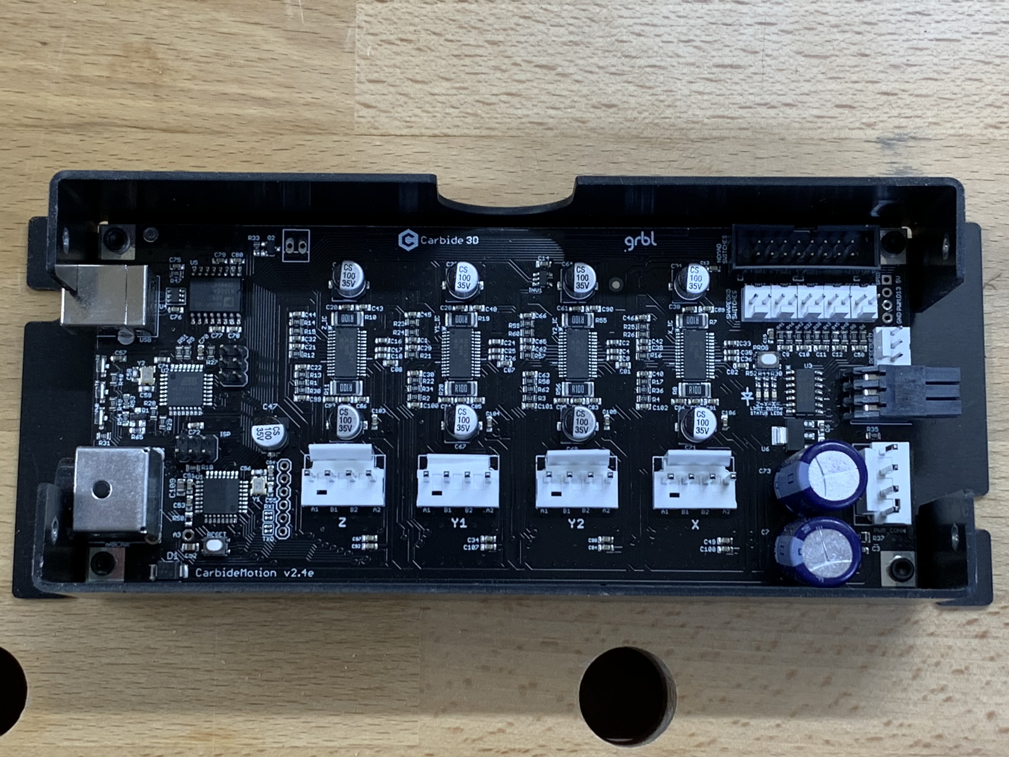
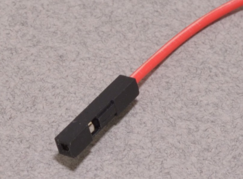
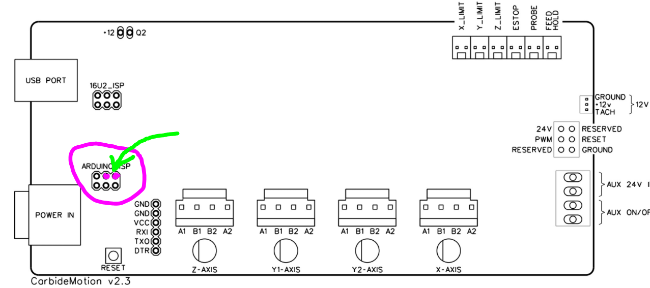
The brown one goes to PWM and the white to ground. It appears they designed this to go with an Arduino which has a place for these wires to plug in. I have the CarbideMotion 2.4e which looks like this:
These are labeled but there are no connectors there for them. I also have the BitSetter and the BitRunner, so when I get everything plugged in, it gets a bit crowded.
Is there another PWM/GND I can use?
Is there a plastic socket/plug I can add to this board? (Note that the other plugs seem to crowd it a lot)
Should I simply solder wires onto the PCB? I would prefer something less permanent.
Any thoughts or suggestions are greatly appreciated.
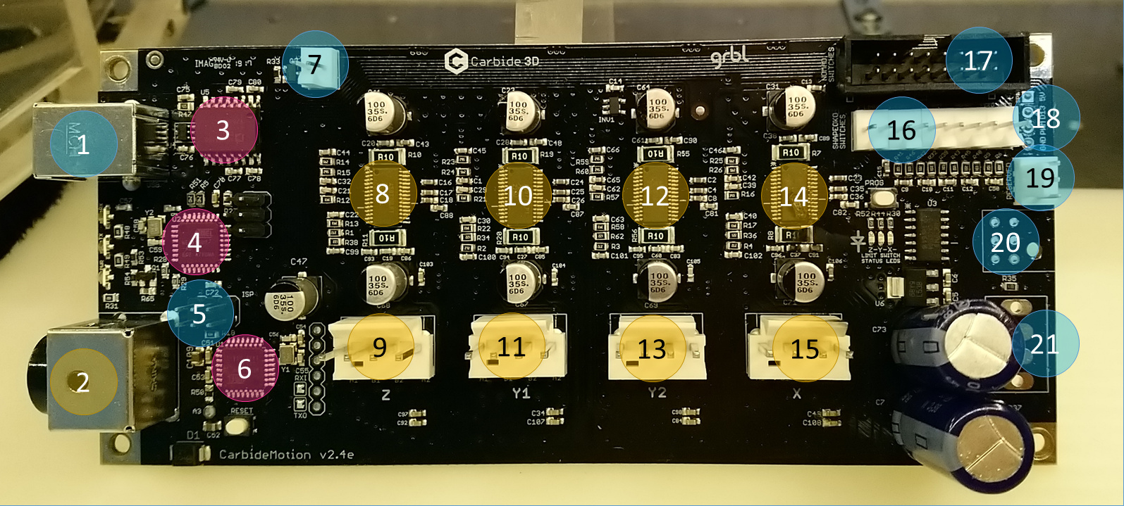
#20 is where the BitRunner connector is, so PWM is not easily accessible there if you do use a bitrunner.
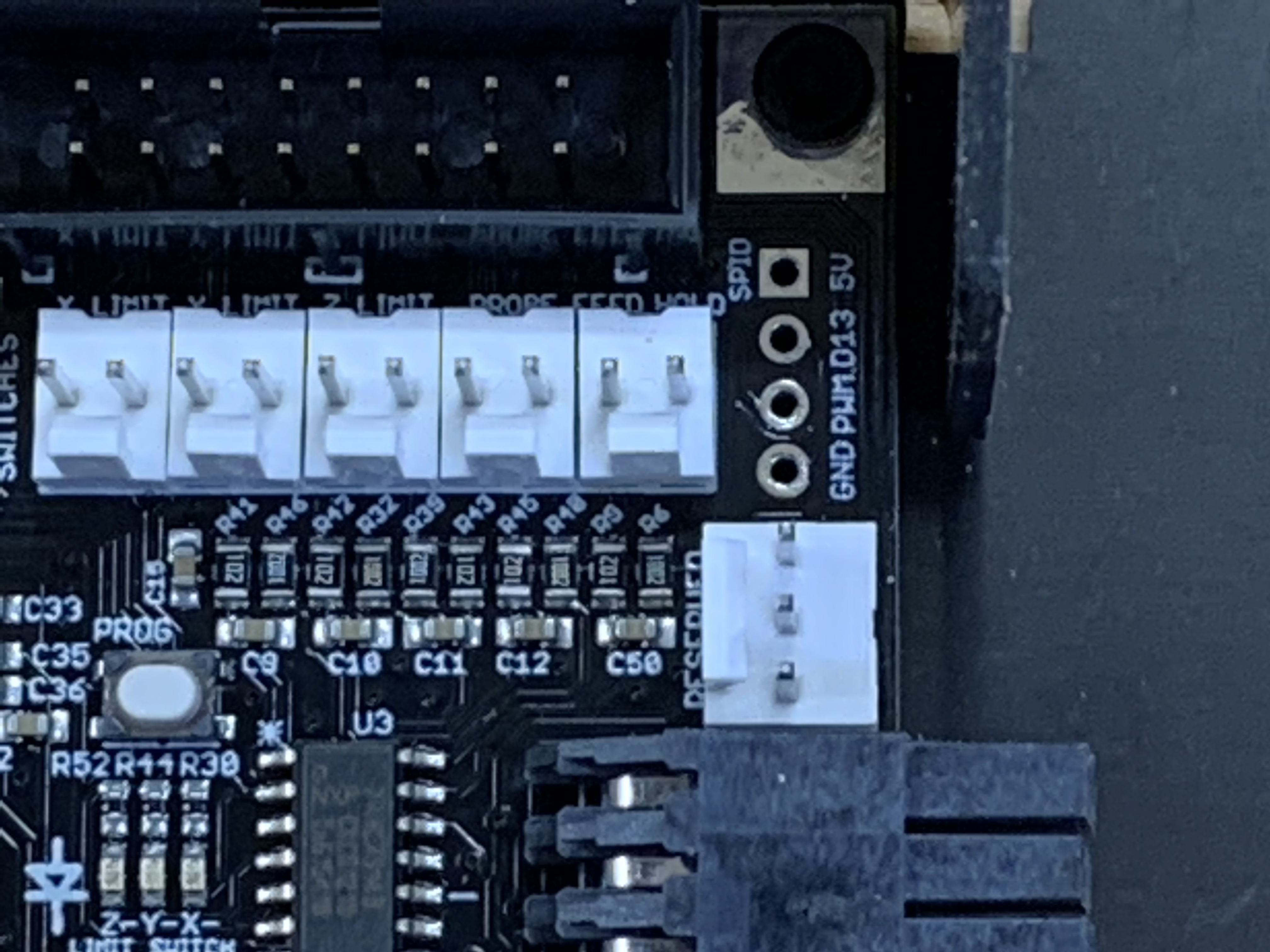
#18 are the plated holed on the upper right side (the ones you mentioned)
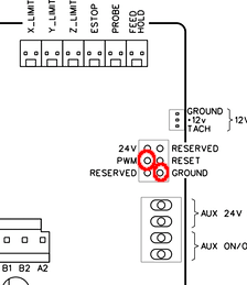
#5 has PWM on the top center pin and GND on the top right pin.
You could either solder some length of Dupont female housing onto the plated holes at #18, which would allow you to plug your arduino style leads, without making it a permanent connection
Or you could replace the pins at the end of your laser wires with single-pin female dupont connectors, and they would plug into the male pins at #5
Thanks, that is helpful. I think I will go with the second option at #5. I have not soldered onto a PCB in a while, plus getting the board out of the case to work on presents some sort of problem. I took the screws out and it seems to be attached (glued) to the case it is in.
For the record: this is likely just the thermal paste between the bottom of the controller and the rail, when it’s been there for a while it sticks. That said I fully agree that not having to remove the board and not having to solder stuff is much easier. I can’t remember actually using the PWM on that specific pin myself, maybe start by double checking the signal there using two female/male Dupont jumper wires.
When you issue an M3 S10000, you should see a voltage. M5 should drop to zero. The voltage you see on M3 commands will be scaled 0-5V based on your max spindle value ($30). So, if your $30=1000, anything >= 1000 will give you 5v. An M3 S500 would give you 2.5V and so on.
I haven’t been able to detect the voltage on the pins at location 5. I don’t know if it’s a failure of my wire crimping (although continuity seems to work well), or if the voltage is not there, or if I don’t know how to properly issue commands on the console.
I tired holding the leads to the sockets at location, with no luck…
Can you share the precise steps you took to activate the PWM when you tested that voltage, just to double-check that there is nothing wrong there? I guess the foolproof way is to just run an air job of any G-code file you have, it will do the M3 command for you, and if your $30 is still at the default value of 1000, it will activate the PWM to 5V then
And your BitRunner works just fine otherwise ? (which would indicate that the PWM is generated correctly on the 6pin connector on the right)
To confirm what’s going on you may want to repeat your procedure as described, but measuring voltage on the BitRunner connector: top middle pin for PWM, bottom left pin (looking into the connector) for GND.
EDIT: you may also want to probe the PWM at the plated hole (upper right side), if you have a suitable pointy probe on your voltmeter
I have confirmed that my BitRunner is working properly. I don’t have the proper connector to be able to test the 6-pin connector for the BitRunner, nor do I have something sufficient to test the plated holes…
Do you know what the connector for the BitRunner is called?
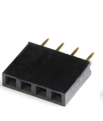
Your next move may be to buy some of those Press-fit header strips that Neil linked to, and insert that in the plated holes, and test there.
Or, find the adequate Micro-Fit plug and use that to connect your laser to the BitRunner connector, but then you would have to unplug the BitRunner everytime you need to use your laser, not quite convenient. Also, that Bitrunner connector is not really meant to be plugged/unplugged dozens of times, it’s not so sturdy since it’s only held on the PCB by its soldered pins.