Origin/consistency of chipload recommendations

@julien @wmoy @Vince.Fab
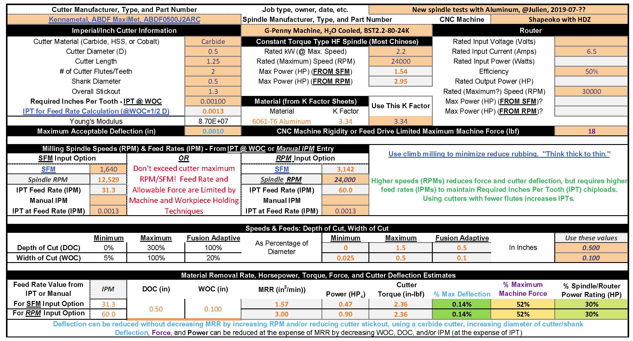
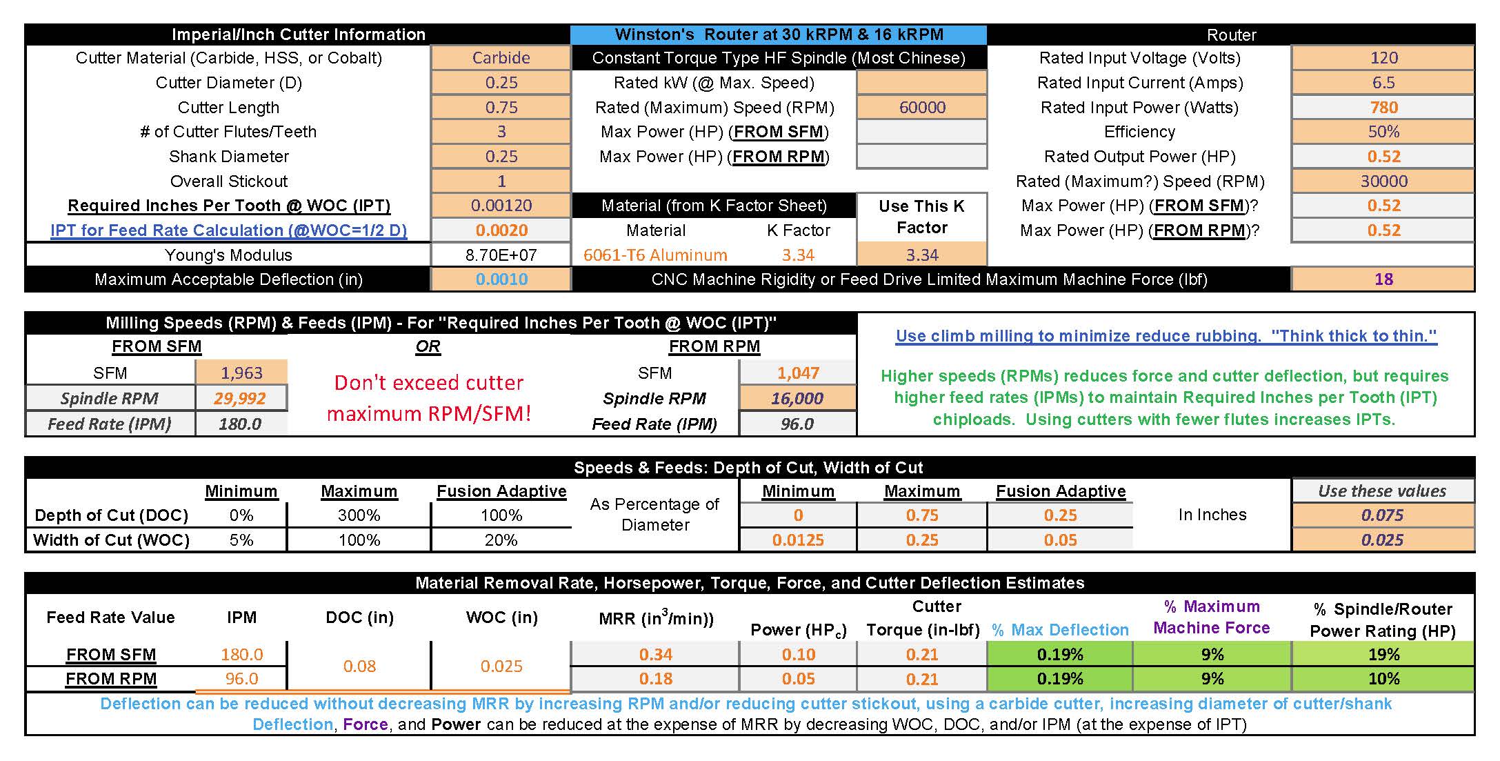
" I follow @Vince.Fab threads religiously, so there is no question that pushing the RPM & feeds can result in spectacular results." I used the calculator Julien, Winston, and Vince.zip (149.9 KB)
to compare what Vince should be able to do with his new HF spindle to what you and Winston posted. Here’s the results:

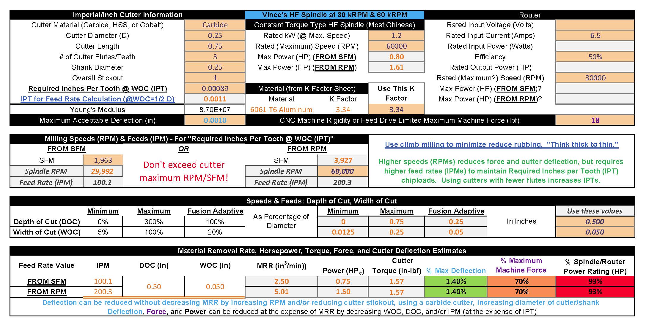
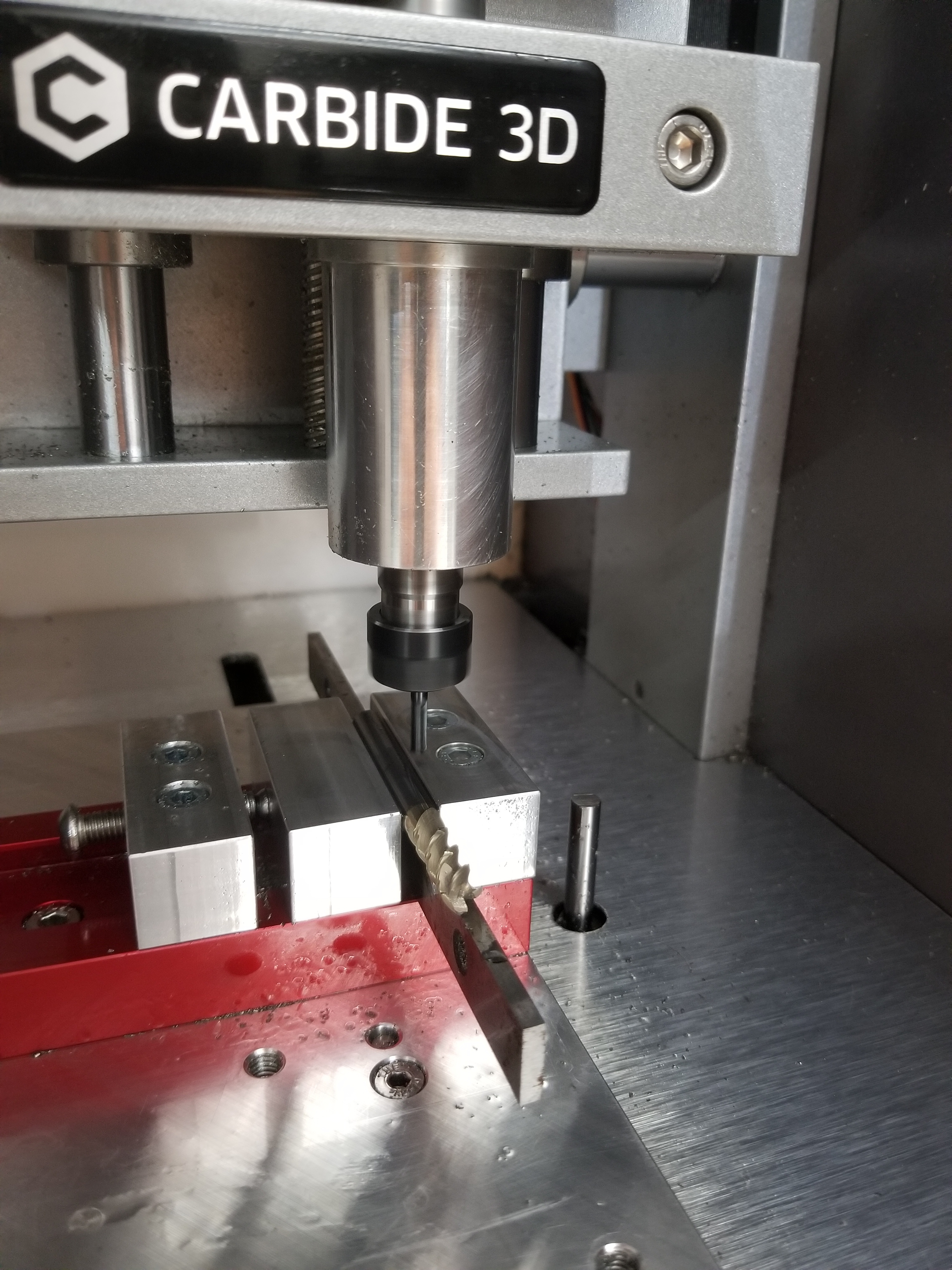
It’s doubtful that a standard Shapeoko could handle the forces necessary for Vince’s 2X diameter cuts, but his heavily modified one might. It looks like that machine doesn’t rely on the Z and X axis V-Wheels.

In what other situation/toolpath would you use the 300% DOC limit you recommend ?” Cutting soft stuff with small WOC and chiploads. Like you would with a router table.

Using anything above 50% while slotting in e.g. oak sounds scary to me (from past tests), but then again I was probably using wrong RPMs at the time, so I definitely want to give it another go at higher RPMs now” Please make sure you have the oak well secured both horizontally and vertically - even axial forces can get huge! If the workpiece comes loose, it could do some real damage because of the high speeds and inertias involved.

"if this is such a clear-cut case of higher RPM is better as long as you keep the chipload above a minimal (0.001") value, why does EVERY feeds & speeds guideline out there (Carbide3D’s table, Winston’s videos, wiki…) recommend RPMs in the lower 10k-18k range, and with chiploads that more or less match what I have in my table ?" Manufacturer’s speeds and feeds likely show what the cutters are capable of doing - i.e. their maximums - which increase with cutter diameters. (Is any info available for Carbide Motion’s endmills? - maybe they aren’t safe to operate at the higher RPMs) You’ll have to ask @WillAdams about Carbide3D’s table, Winston about his, and Bob Warfield about his.

"why does using higher chiploads at lower speeds also seems to work to keep the cutter cool ? I (like many others) have had nice cuts in plastics going at min RPM, low flute count, and feeding fast (i.e. using high chiploads). And successfully cut hard woods at “high” chiploads with no noticeable heating of the cutter. I don’t deny this might not be the right way, but why does it work, if it’s supposed to generate heat and heat buildup on the work piece?" Maybe because the MRRs are so low that negligible heat is generated?

"why would it be a such a widespread recommendation to keep cuts relatively shallow on hobby CNC machines it is wasn’t right ?" Beats me!

"p.s. : I am not trying to argue forever, this thread is long enough as it is, but now that we are debating this (and that I’m learning so much in the process!) we might as well get to the bottom of things, and I hope to end up with a conclusion that my fellow Shapeoko freshmen can apply in day to day casual/hobbyist use. I couldn’t agree more (except about the thread being long enough as it is). Again I’m certainly no expert on this stuff - I’m still just trying to understand it myself. I appreciate any and all feedback. I didn’t realize that we were arguing!

3 Likes

While it is fun watching an adaptive attack of a block of aluminum, adaptive doesn’t seem like it offers much for someone machining a single piece of material into several parts.

For example, I recently cut a 12" square piece of particle board into approx. twenty-five 1-5/8" D “wheels.” I can’t see what adaptive would bring to the table for an operation like that, but maybe I’m missing something?

I also routinely process polycarbonate sheets into parts as small as 1.25" square. There is a 1/8" deep pocket and a profile cut, basically.

The speeds and feeds we use are dictated by the type of machining we’re performing. I’m doing a lot of what you would call “slotting.”

And I could up my RPMs but I don’t want the high-pitched noise. So I literally try to keep my Dewalt router around 2-3 on the speed dial, and let that dictate my feed rate based on the tables we’ve been discussing. I start conservatively on the DOC and for repeat projects, may increase the figure depending on the cut quality.

I can’t see any other way it could work, but I’d be open to suggestions.

2 Likes

@gmack:

  • thank you for taking the time to answer all my points, much appreciated.
  • indeed we were not “arguing”, that’s just my imperfect use of English words, also probably because for a French guy “arguing” is synonymous with “discussing” :slight_smile:
  • high DOCs : got it, and actually I fully agree then. I was implicitly writing this guideline with regular slotting in mind, for which 300%D on a (stock) Shapeoko is close to suicidal, but indeed if WOC is small enough then DOC can be quite large, and your router table example is the perfect illustration. The tricky part is, on a Shapeoko with a “simple” CAM program like CarbideCreate, where you do not have access to e.g. helical ramping, initiating a pocketing cut at 300% DOC will not work well because at the beginning of the toolpath, the tool will effectively be slotting at 300%D. Anyway, I will definitely rephrase this guideline.
  • workholding for high-forces cuts: yes, this is a good reminder, that I should include in the workflow (i.e. if the predicted force is anywhere above XX%, make sure the workholding solution is compatible)
  • chiploads: the more we discuss, the closer I get to being convinced that you are right : that what matters is maintaining chipload above a minimum somewhat-universal value, and then provide an indication of the maximal acceptable chipload for a given cutter diameter. Since I need to see for myself and on my machine that this theory works across a wide range of materials and cutters, I’ll start testing (again).
  • shallow & wide versus deep & narrow cuts: I wonder if we should come up with a recommendation on the DOCxWOC value, instead of DOC alone. A slotting cut 50%D deep and (by definition) 100%D wide would be equivalent to a deep cut at 300%D with a 17%D WOC. It also would relate nicely to MRR once feed rate is added in the mix. Could the rule just be to keep (DOC/D) x (WOC/D) around 0.5 ? Just thinking out loud.

@cgallery
My point exactly: in the feed & speeds & WOC & DOC selection process, one needs to be able to make a decision that best suits the usecase at hand, and oftentimes for Shapeoko users that is profile cutting, i.e. slotting, and therefore shallow is the right thing to do. Also agree for that for a profile cut adaptive is often not relevant (except in metal, where I find it much more comfortable than very-shallow slotting)

2 Likes

@cgallery
Yup, the sound of the Dewalt is a lot more annoying than even the Makita at high speeds. That’s why I often wear these at the shop. For dust protection I wear this. Safety glasses are a “no-brainer”.

There will still be noise with a quiet spindle, but at least you’d be able to hear the milling process. IMO the best way to get the most out of the Shapeokos is maximize spindle speed to minimize force. But, the endmills have to be able to operate at the high speeds, these can run at up to 100 kRPM. It doesn’t sound like you have a need for endmills larger than 1/4" diameter, so the @Vince.Fab 60 kRPM HF spindle might be worth considering as an upgrade.

I’ve heard that this is a good introduction to Fusion 360. Since it’s currently on sale for $12.99 (the last day?), I bought and plan to use it to learn Fusion 360. Note that the Fusion 360 “guru” that uses 0.001" initial chiploads for metal also recommends keeping a log of what works for each job. With the Speeds and Feeds workbook that can be done by simply making and saving a copy of the “working spreadsheet” that contains all of the relevant cutting parameters. (That’s what I did in the latest workbook for the three different approaches.) I’ll add a field for endmill details.

2 Likes

So, today I re-read this thread from the top, with a fresh look.


DISCLAIMER: this is an attempt at summarizing the takeaways from 200+ posts in this thread, so bear with me please !


  • There is a consensus that the chipload should always be at least 0.001" (possibly down to 0.0005" for endmills below 1/4")
    • climb milling is better when targetting such small chiploads (@gmack: “thick to thin” is less likely to rub)
    • tool must be sharp (or it becomes impossible to cut reliably at this small chipload)
    • on small endmills (1/8" and below), runout must be low (sub-0.001") to accomodate this chipload target without risk of breaking the tool. Tapping the endmill works great to reduce runout (@Vince.Fab, @PaulAlfaro)
    • chipload can be increased up to a max value that depends on the endmill diameter and the material ([see table]), however it is not recommanded to significantly increase chipload as it requires more cutting force/generates more heat (@gmack)
  • SFM is probably not a good enough input to determine RPM across a wide range of materials:
    • see separate thread from @The_real_janderson, and the conclusion that on Shapeoko we should adopt the “Datron-style” milling and focus on chipload rather than SFM
    • Using the SFM value can still be a reasonable backup plan where no other starting point exists (@PaulAlfaro )
  • Instead, RPM should be:
    • As high as possible/maxed out (@griff uses 30K always), to minimize cutting forces (@gmack) as well as to shift resonances/chatter to higher frequencies with lower amplitude, to improve finish quality (@cgallery)
    • or at least “as high as one can tolerate/feel comfortable using”
    • low RPMs may still work fine (assuming the minimum chipload is maintained) on forgiving materials with a wide range of acceptable cutting parameters, and at low MRR’s
    • in all cases, feedrate must be adjusted accordingly to maintain the minimal chipload value
  • For DOC, two possible strategies:
    • small DOC (5 to 50% D) and large WOC (50 to 100%D)
      • @cgallery uses 50% of manufacturer recommandations and increases DOC from there if needed
    • large DOC (up to 300%D) and small WOC (10 to 20%D)
      • for adaptive or pocketing with small stepover, assuming adequate ramping into the cut.
    • there is possibly a rule of thumb to be found for DOCxWOC
  • MRR, power and cutting force analysis is very useful:
    • MRR to compare the relative efficiency of various settings
    • Required power is derived from the material’s specific K factor / unit power, which can be measured, and an interesting set of K factors is available (NYCCNC+ @gmack measurements). Computed power can then be compared to the power limit of the router (~500W max) or spindle (1000W+)
    • Cutting force is derived from power and endmill size, and can then be compared with the Shapeoko’s limit (~18-20lbf @gmack)

Does this sound about right ?
In the meantime I’ll go back to cutting tests to experiment with all of this and collect evidence.

6 Likes

Seems to, can it be converted into a system easy enough for newbies to use?

1 Like

looks well compiled to me @Julien, you’re on a war path. haha

1 Like

That’s still the ultimate goal, and I have a feeling it’s doable, the newbie version could boil down to following guidelines for just 4 values:

  • RPM => the highest RPM value you are comfortable with.
  • chipload => 0.001 + 50% margin (runout, dullness, and other wrong but real reasons…)
  • DOC & WOC => shallow and wide strategy (it’s unlikely a newbie will be into adaptive/HSM)

and then use those values in worksheet to compute everything else, and watch out for cells turning orange or red.

1 Like

Not sure if anyone has brought up tool balance. Usually I’ll run tools through the rpm range and cut where it feels the smoothest. The higher the rpm, the more important tool balance is.

The 60krpm spindle now has a compatible plug after ordering a few kinds. Still need to design and machine a bolt on 62mm holder as the one it came with is really, really ugly. Personally I keep around a 3000 sfm limit on aluminum, would run 1/4 at 45,000ish.

Another good practice is to cam out to a minimum chipload and use realtime feed overrides to increase chipload. Many times I’ll find myself going 200% to increase tool pressure and stabilize the cut. Its very easy to hear this.

Chiploads minimums DIDNT work on this :rofl:

2 Likes

Looks like you have a recipe. One question, how do you deal with V bits and tapered bits?

1 Like

I hoped no one would ask :slight_smile:
This is on my todo list…

WHAT are you doing to that poor endmill? :slight_smile:

@Julien
on small endmills (1/8" and below), runout must be low (sub-0.001") to accomodate this chipload target without risk of breaking the tool. Tapping the endmill works great to reduce runout (@Vince.Fab, @PaulAlfaro)" I really doubt that when cutting forces increase to useful levels for useful usage times. Those sinusoidal forces, which are similar to those delivered by an impact driver, are applied to the cutting surface of the endmill get “amplified” by the length of the sickout. But, you shouldn’t have to bother with that anyway with your HF Spindle and collets - which claim 0.01 mm (0.0004”) runout. Let us know if that’s real and how it works out!

" SFM is probably not a good enough input to determine RPM across a wide range of materials:

  • see separate thread from @The_real_janderson, and the conclusion that on Shapeoko we should adopt the “Datron-style” milling and focus on chipload rather than SFM
  • Using the SFM value can still be a reasonable backup plan where no other starting point exists (@PaulAlfaro )"

"chipload can be increased up to a max value that depends on the endmill diameter and the material ([see table])," Use manufacturers speeds and feeds recommendations for that!

Some cutter manufacturers, like Kennametal, use SFM for their speeds and feeds recommendations instead of RPM. That’s why we should leave the “SFM Input Option” in the workbook.2019-07-10 Speeds and Feeds Workbook.zip (150.2 KB)
Here’s what one of their endmills should be able to do for you with your HF Spindle if your machine can handle 9.4 lbf (minimize spindle stickout!)

"there is possibly a rule of thumb to be found for DOCxWOC" Maximizing DOC maximizes tool heat and wear distribution.

1 Like

And you even filled the worksheet with my future spindle settings…so cool.
It has arrived by the way, I’m picking it up on Saturday!
Too bad that unlike @Vince.Fab, I need sleep, and it’s 00:22 and I should really turn off my computer now.

2 Likes

@Julien
" chipload => 0.001 + 50% margin (runout, dullness, and other wrong but real reasons…)" shouldn’t compensate for dullness by pushing harder.
" DOC & WOC => shallow and wide strategy (it’s unlikely a newbie will be into adaptive/HSM) "Shoudn’t “newbies” learn to do it the right way (deep and narrow) too?

I firmly believe if you can slot you can do anything and it’s a great exercise to do in all types of materials.

2 Likes

@Julien
"indeed we were not “arguing”, that’s just my imperfect use of English words, also probably because for a French guy “arguing” is synonymous with “discussing” I’m really impressed with your understanding of English grammar and writing skills (they’re a lot better than that of many engineers that I used to work with). Did you spend time in the US or UK? Do you use software assistance? Do you speak that well too?
"The tricky part is, on a Shapeoko with a “simple” CAM program like CarbideCreate, where you do not have access to e.g. helical ramping, initiating a pocketing cut at 300% DOC will not work well because at the beginning of the toolpath, the tool will effectively be slotting at 300%D." Doesn’t CarbideCreate allow you to define a starting pocket perimeter toolpath using a tool defined as DOC = D followed by another pocket clearing toolpath using a tool defined as DOC = 3X D?

  • runout adjustment and how long it holds: NYCCNC’s, Paul’s, Vince’s, and my own (very limited) tests seem to indicate that it holds “long enough to be useful”, probably because we are testing at low power/MRR/forces scenarios, but that is a very likely usecase in micro-machining isn’t it ? I will definitely check the runout of the new spindle, from what I heard it is a bit unpredictable so here’s to hoping I do not get a lemon.

  • max chiploads: yeah manufacturer recommendations are relevant as far as the endmill is concerned, but practical limits once it is installed on a Shapeoko are lower, from my experience. Just now if I google “chipload recommandation” and open a random link (e.g. this one), it tells me to use a 0.004" chipload for a 1/8" endmill in aluminium. Nope, I am probably not going to try that. Funny story: this same PDF has this statement that you wouldn’t like: “Your goal is to select the lowest RPM possible for each application:slight_smile:

  • worksheet: your version gets better every day, I would really like to include it as is in the e-book as a reference calculator at the end of the feeds & speeds chapter, along with step by step description/instructions on how to use it (because let’s face it, if a total newbie opens it for the first time, or any other similar calculator for that matter, it will look daunting, while in fact you only need to play with ~4 inputs)

  • deep & narrow cuts: theoretically you could use CarbideCreate to “simulate” e.g. helical ramping, by first cutting the center part of a pocket using conservative DOC (<1D), and then creating a second toolpath that would clear the rest of the pocket at high DOC / small WOC. With no rest machining option in CC that would also mean you would need to create extra geometry to define two pockets. Wait, then the second pocket would look more like a very large slot, and CC would decide to start cutting in the middle of it, not the borders. Sounds like a headache, and IMO it is an unrealistic expectation from a new user to master this kind of subtleties, it would make the learning curve even steeper. I agree with Vince that slotting needs to be mastered anyway, and this is one of the most common cutting scenarios for Shapeokoers. Yes it’s wearing out the tip of the endmill only, yes it means moving away from the optimal feeds & speeds/MRR, but still, there should be a guideline for how to cope with that situation.

  • English: nope, I never lived in the UK or US but I guess working for GE in France for 10 years, reading all of my books in English, and binge-watching Netflix shows with subtitles turned off helped. What I wish people did is correcting my mistakes, but no one wants to be rude so they don’t. Everybody please don’t hesitate to correct my (recurring) small mistakes, I will be grateful not offended!

3 Likes

Gerald, I suggest you try to use the basic tools available (read free) to most users like Carbide Create and Easel in particular to create a few projects. There are no fancy toolpaths and options are pretty limited. Heck, CC does not even have rough-in and detail passes available. Even the VCarve family products while very powerful do not have many of the features like adaptive clearing.

@luc.onthego @Julien @WillAdams
I’m waiting on my emailed download link for CarbideCreate (I’ve only used VCarve so far.)
But maybe I wasn’t clear in my proposed workaround. Would this work?

Assuming you want a 300% D deep pocket. Define a starting pocket perimeter toolpath using a tool defined with DOC = 100% D (and feed rate 1) which would you would run/execute first (it would take 3 passes). Define a follow-up pocket clearing toolpath using a “different” tool defined with DOC = 300% (and feed rate 1 or 2) which you would run/execute second.