I am trying to cut out my first real project, which contains several toolpaths with two different bits. I’ve drawn it all using Carbide Create V7.
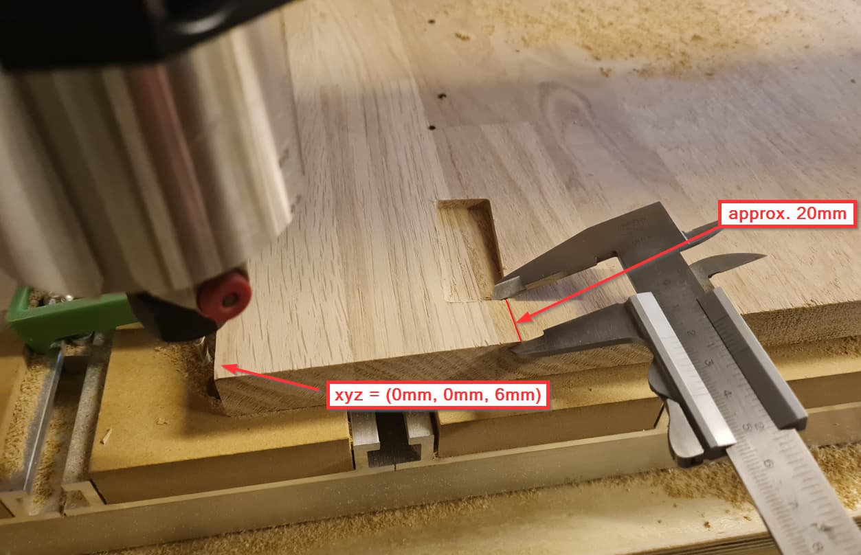
I initialize the XYZ-zero manually and the bit height using the BitSetter. Everything seems to be ok if I e.g. make it move to “rapid to current xy” and “rapid to current z + 6mm”.
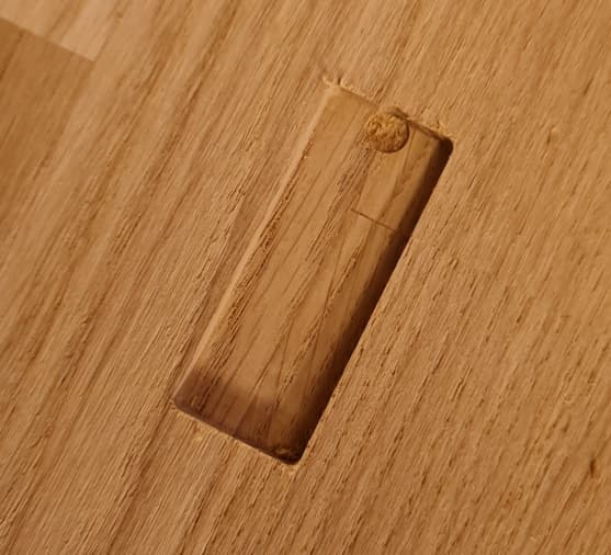
However, during cutting, the different toolpaths are not aligned correctly. For example, a drill hole that is supposed to be in the middle of a pocket is put at the top instead.
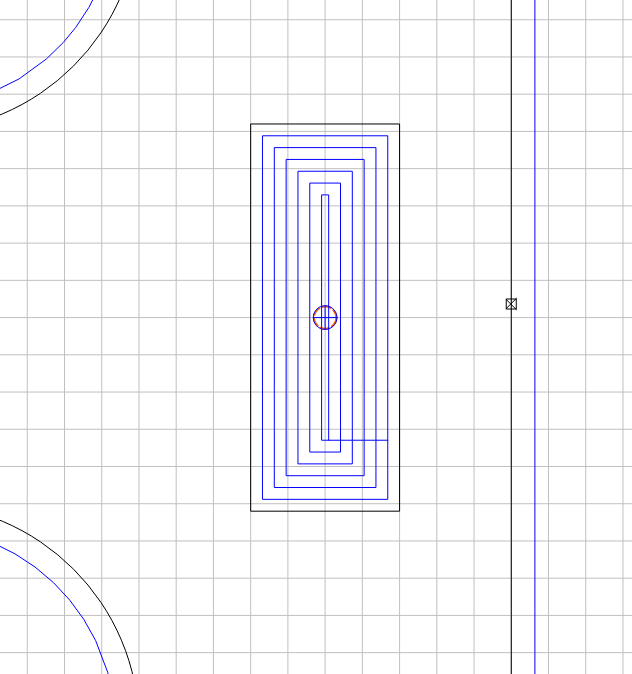
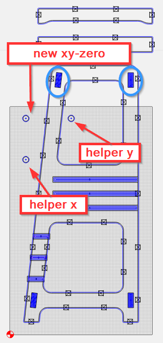
My hypothesis for why this is happening is that I am trying to cut out a figure that is larger than the cutting area. I saw this youtube video and was planning on following his approach of re-calibrating the XY-zero for the second round. However, I notice that the Shapeoko tries to cut things that are outside of the defined stock size (like the pockets I’ve circled in blue), which causes it to hit the end sensors. Not really sure why this would make it drift away from the XY-zero, but it is my best guess.
It sounds like your machine might be skipping/losing steps. If you have the machine return to zero after finishing the toolpath, does it go back to the same spot?
Yes, that’s the strange thing. The picture I took off the bit positioned at (0,0,6mm) is after the cut (though I didn’t complete the full run when I realized things were off)
As @WillAdams said you cannot go past the mechanical limits of your machine. If your project is bigger than your cutting area then you must use a procedure called tiling. Carbide Create does not support that directly. You can poor boy it by making your project into two parts. However to make sure if your material size on an XXL is 10" X 10" you can cut beyond the boundary of the material. You cannot cut beyond the boundary of the mechanical limits. I cannot remember the exact specs of an XXL but lets just say 32" x 32". If you put your 10" material in the middle of your spoilboard you can draw objects off the material and it will be cut just fine. I often will cut past the edge of my material when I need the cut to not be rounded on the end of a slot. If you draw a slot that goes right to the edge when cutting there will be a rounded corner left at the edge of the material. I extend the slot past the edge of the material and I get the full width of the slot past the edge.
However what you described above sounds like you are losing steps. The origin in the software never moves but the physical location of your X Y and maybe Z can be lost due to lost steps. The Shapeoko/Carbide Motion still things it is cutting exactly where it is supposed to but is not. As long as your project is within the bounds of your machine’s cutting area you can cut past the edge but not past the edge of the mechanical limits.
Check your pulleys on each stepper motor for loose set screws. Check your belt tensions and inspect your belts for bad teeth if you have been grinding on it. Power off your machine and back on. Initialize and then job to the 4 corners and make sure your machine can go there with no problems. During jogging your machine cannot move past the configuration area sent. So when the CAD program writes out gcode if you try to send your machine a mile off the edge of the physical limits the machine will try to go there and just grind. Gcode is not restricted where it will try to move where jogging is restricted by Carbide Motion.
Look up tiling if you have a project bigger than the cutting area.
That sounds like what has happened. I guess the reason why it was able to find the XY-zero after this was because it re-initialized before going there.
That being said, any idea how the youtuber I linked to did what he did? Maybe he drew the top part after completing the first run?
Thank you for your in-depth reply. I have already looked a little bit into tiling, but I thought the youtube video I linked to was a hack to get around this. I thought the end sensors would turn off the movement before it physically crashed. But I guess not. I’ll look more into tiling, then…
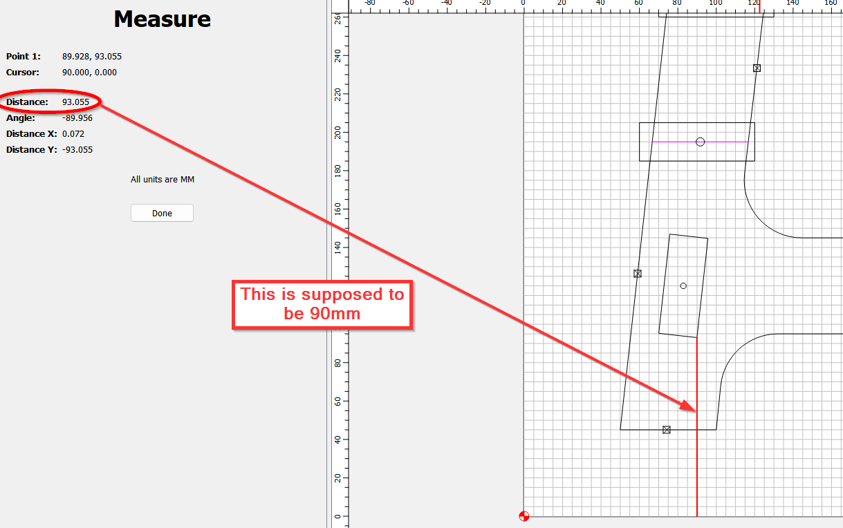
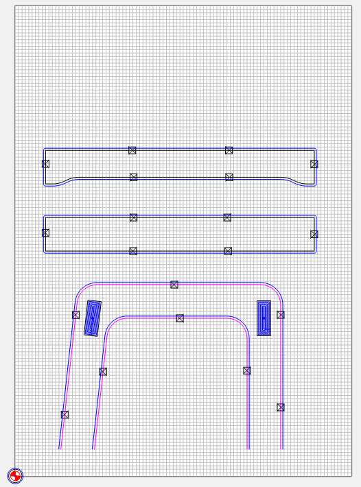
@WillAdams Do you think this will work, then? I’ve split the original into two pieces, and moved the upper left calibration-circle in the first image into the xy-zero of the second one.
if you are using Carbide Motion to send GCode, carbide motion (nor the machine without soft limits set up, which is not recommended by support) will not stop the machine from traveling outside the physical limits. I had this conversation the other day in a different thread because i wanted to make sure before i sent my nomad crashing into itself.
The “Adding geometry to cut as a pocket with a finishing pass” post you sent me was great. I’ll make sure to incorporate this into my designs. However, I have two questions:
Could you elaborate on the offsets you used? I didn’t quite understand why you only offset with half of the bit’s diameter.
Is this approach equally recommended for woodworking and metal, or is it most crucial for metal work?
Offsetting will vary based on the effect one needs: half the tools diameter for a (very generous) roughing clearance — a more typical value is larger than an expected defect or 1/8 the tool diameter. Offset by endmill diameter plus 10% for a pocket one can fit a tool into.
I use it for both materials. It’s probably not as critical w/ the newer single flute and coated tooling and feeds and speeds, but it’s good working practice.