Overly Complicated Pen Holder

A few months ago I posted that I was a little irritated at how difficult it was to swap pen colors when I was making multi-colored yard sale signs, and how I had planned on designing a new pen holder that would hopefully eliminate the need for having to precisely locate the pen tip height every time you needed to swap out the pen.

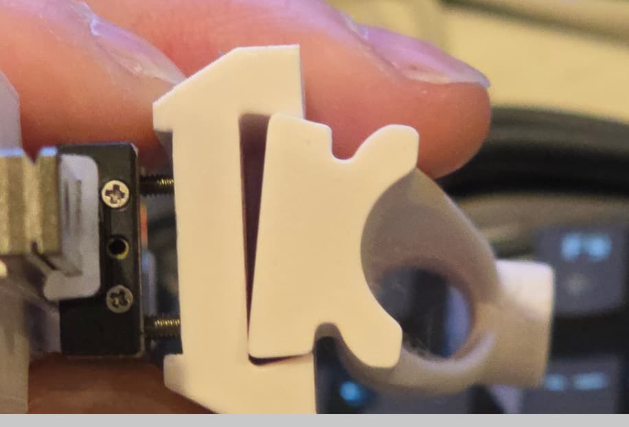
Well, here it is - at least the design. I have the models ready to print, but my printers are printing other things at the moment, so I am a bit early to be posting pics, but I am going to do it anyway. :slight_smile:

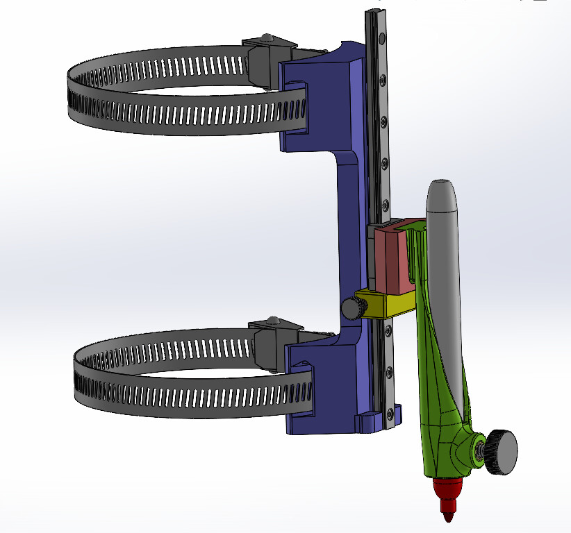
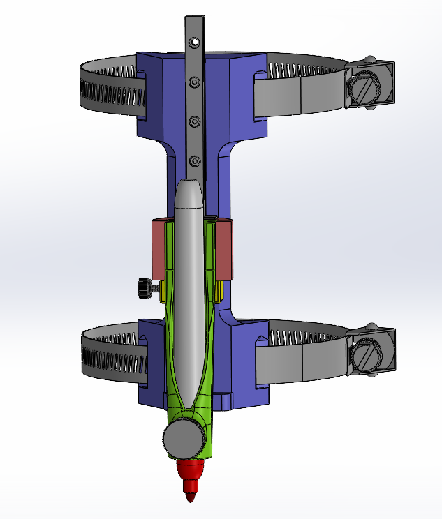
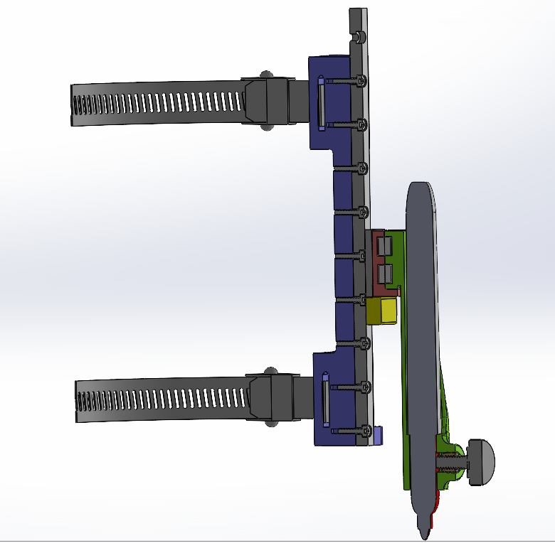
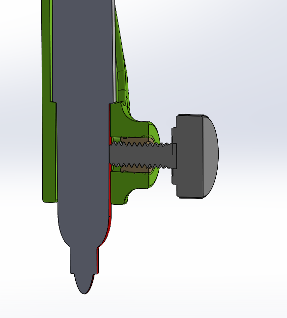
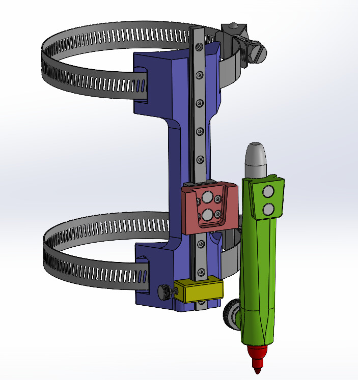
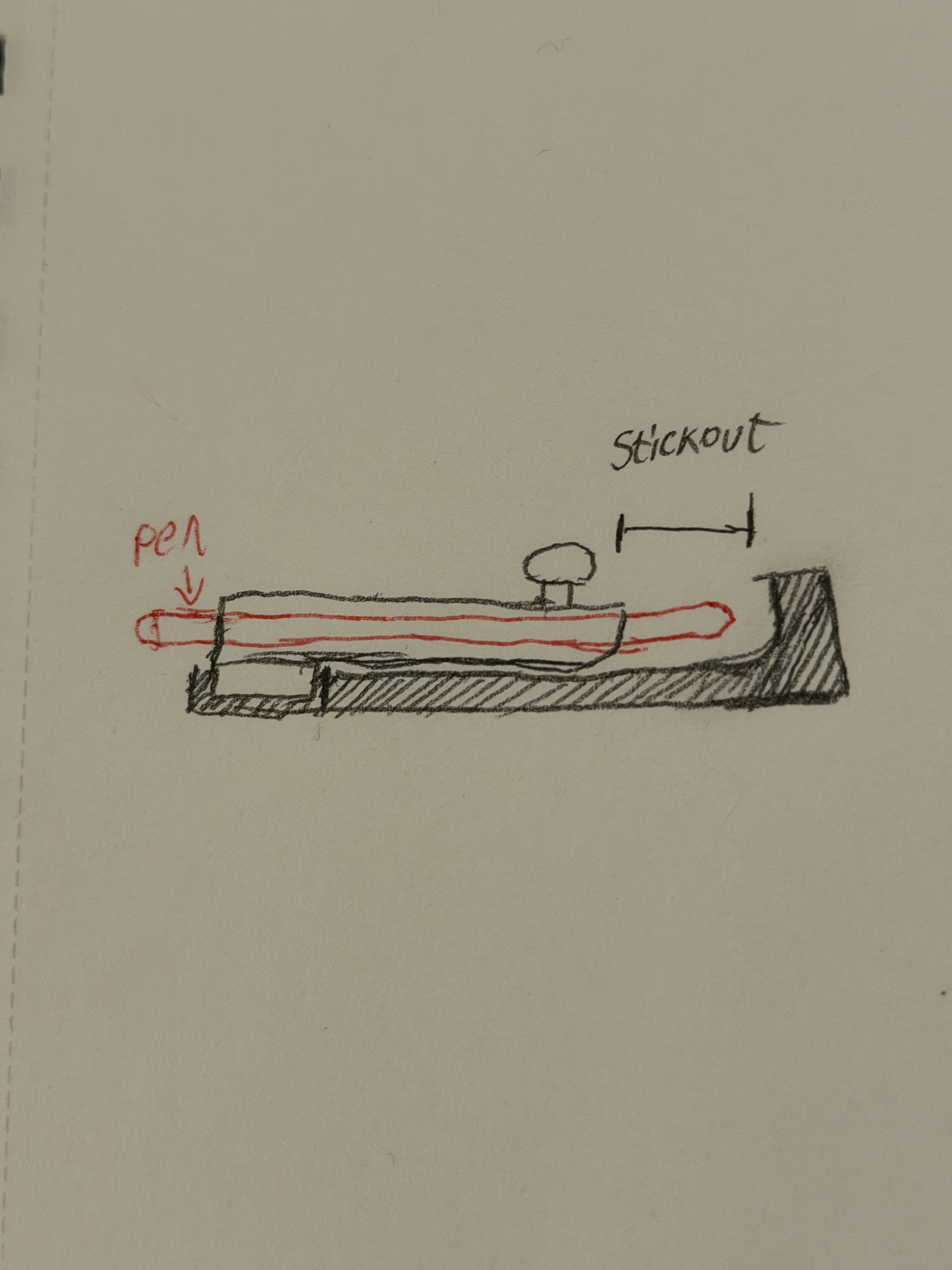
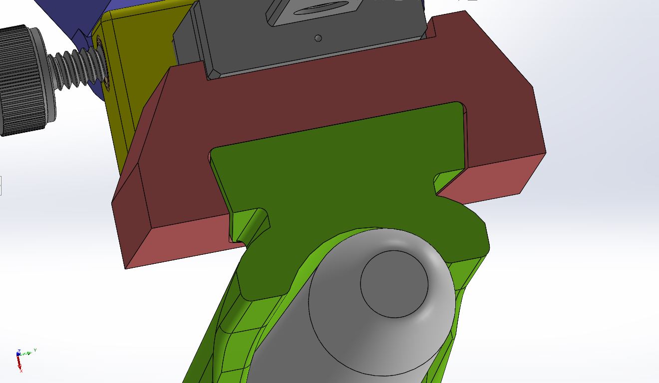
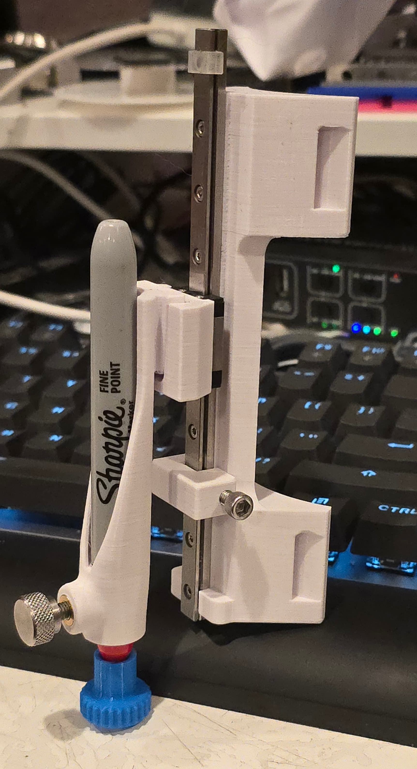
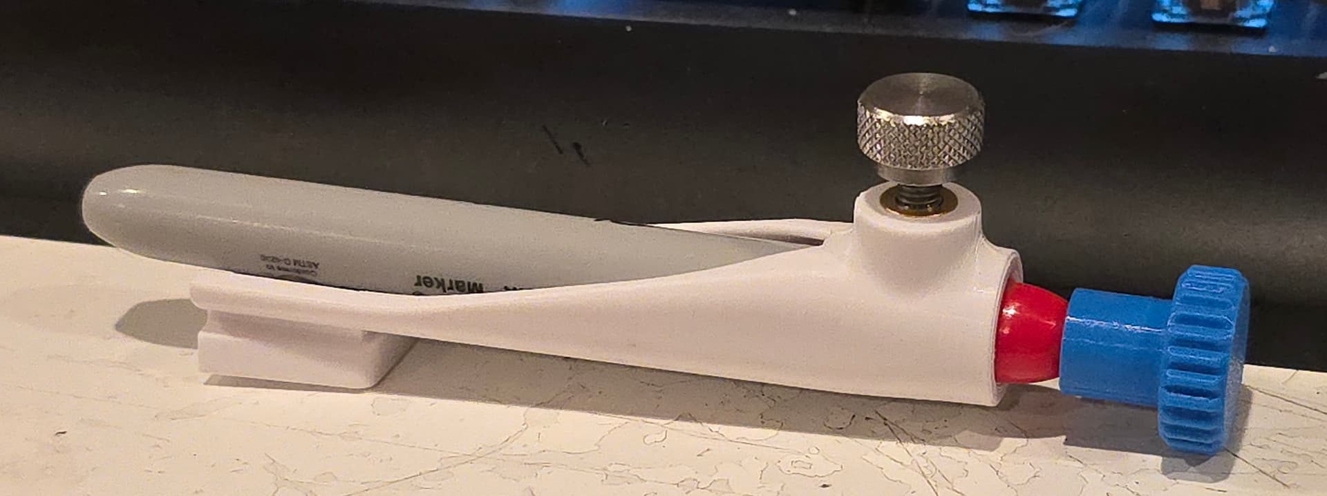
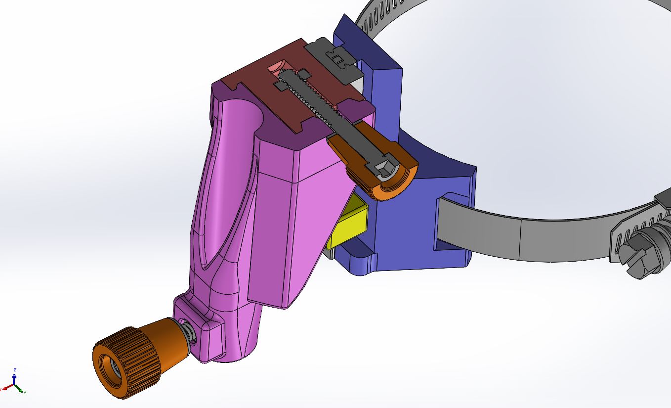
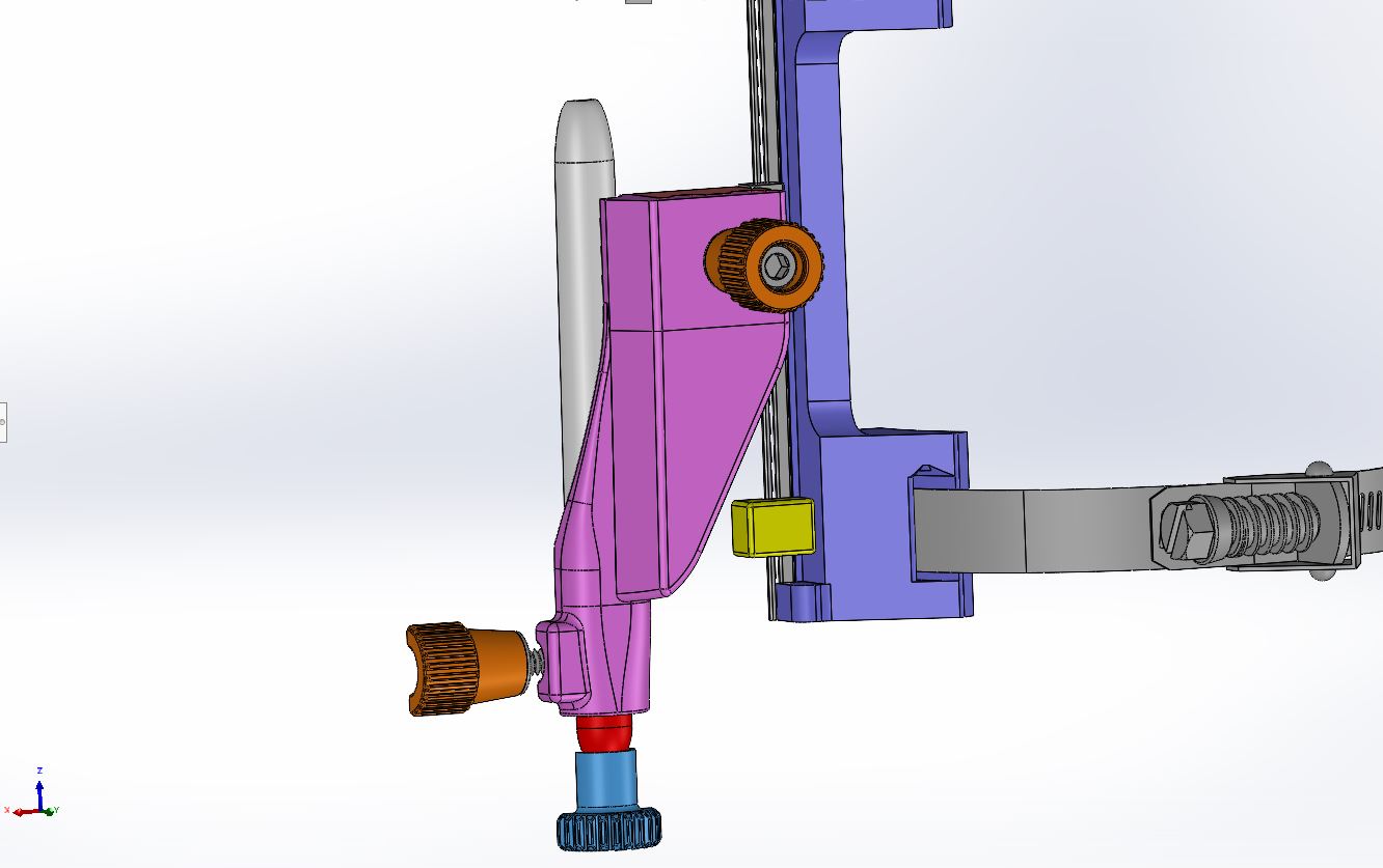
The idea is that if you are using a Sharpie (or similar designed felt tip marker) with the little lip on it, they should index on the shoulder of the pen in the green pen holder. The reality though, is that all of the pens have a slightly different distance from that shoulder to the pen tip. So, there will also be an indexing stand that should be used to set the pen tip distance to standardize all of the pens / pencils you will be using.

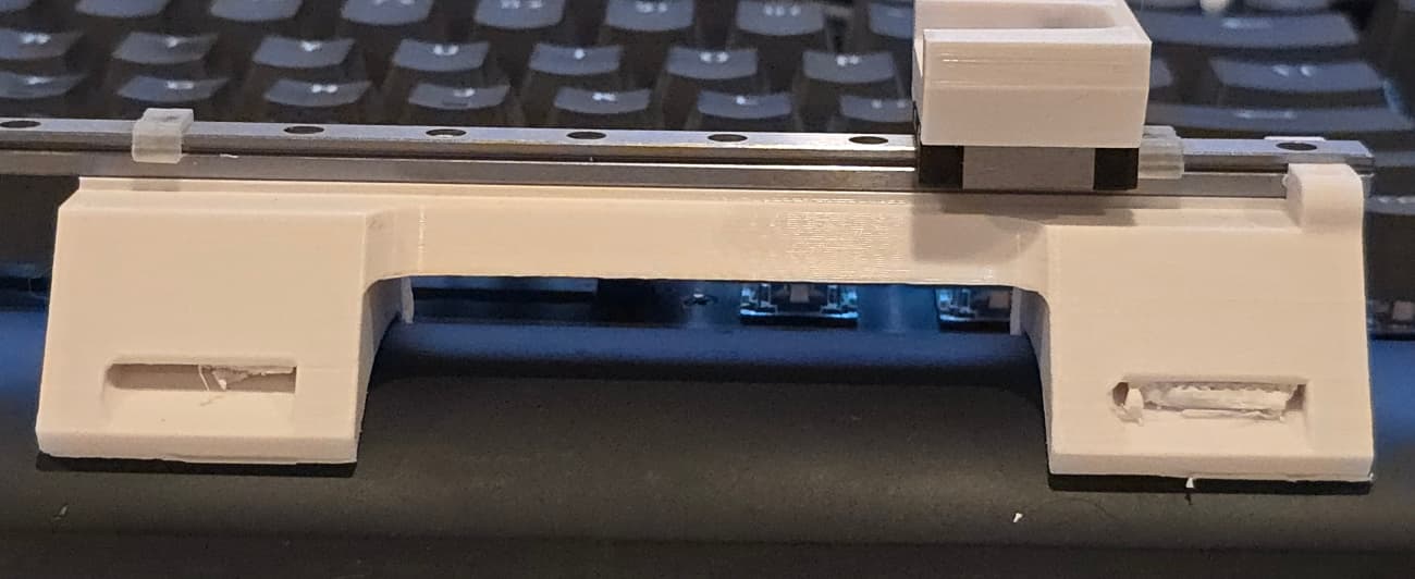
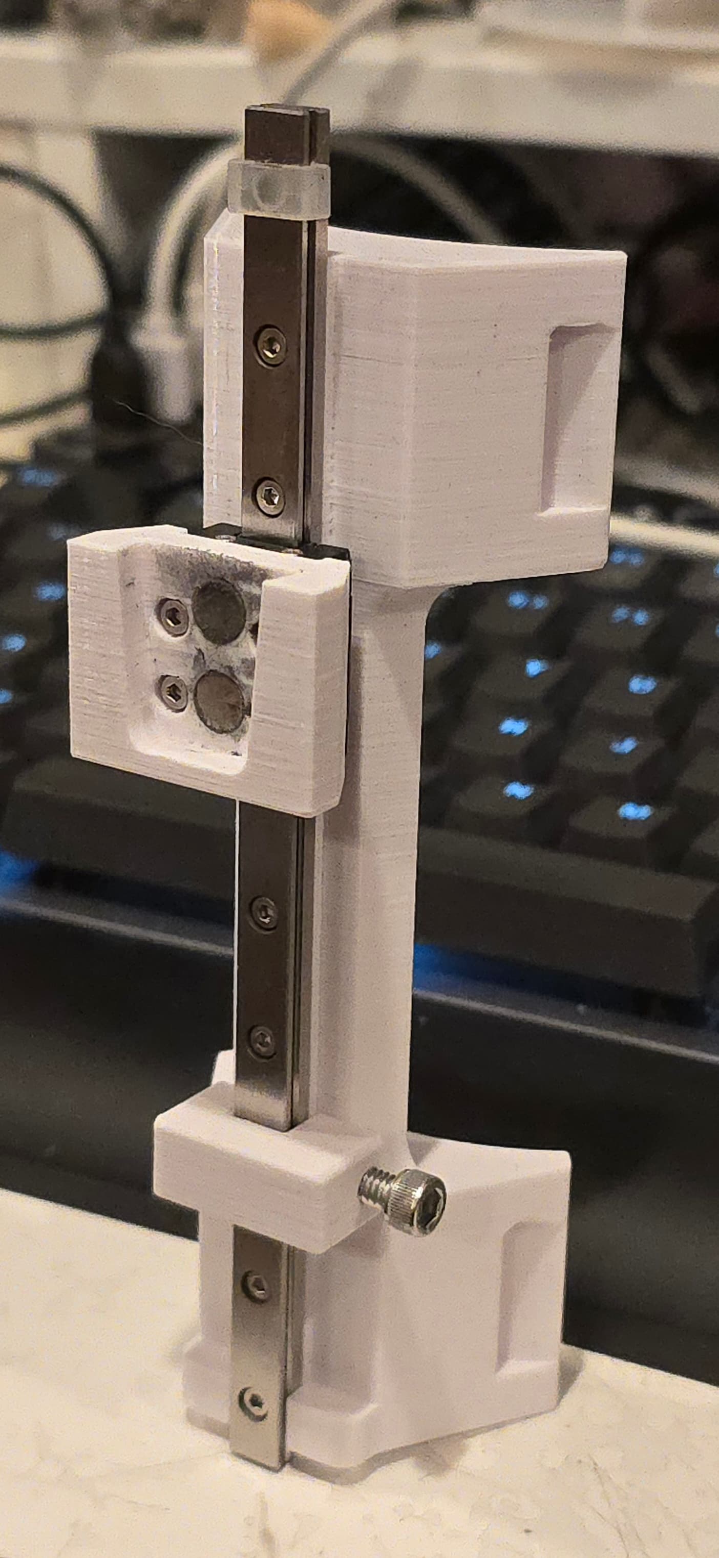
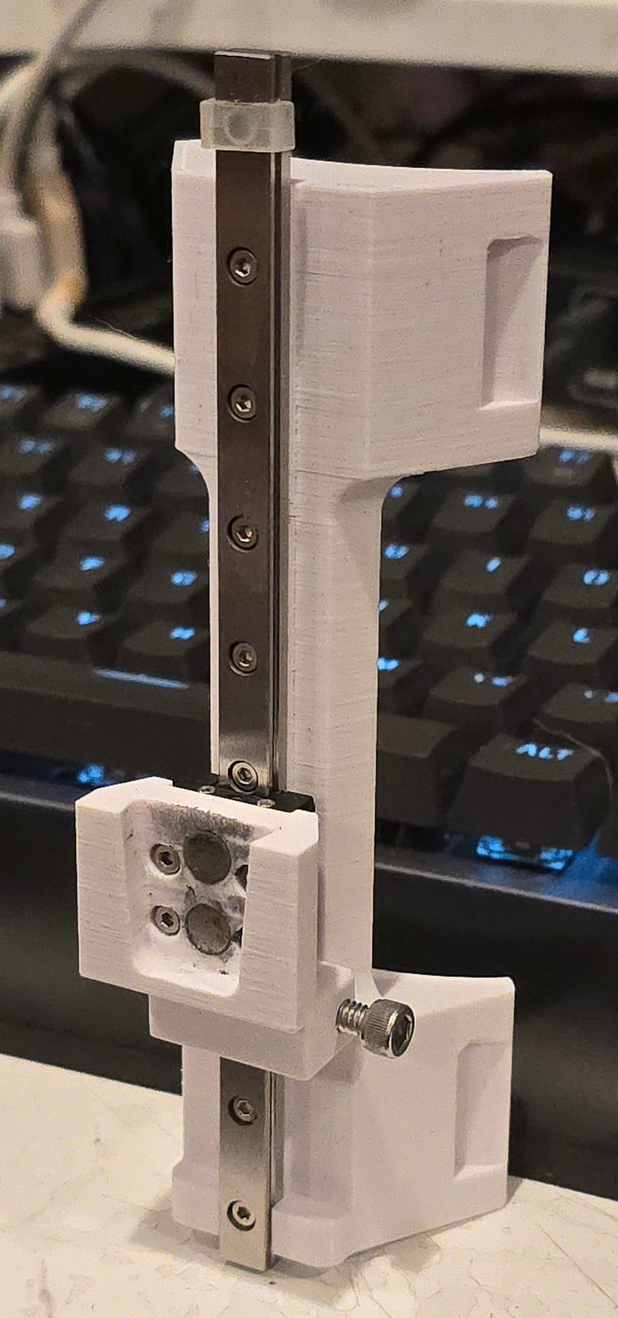
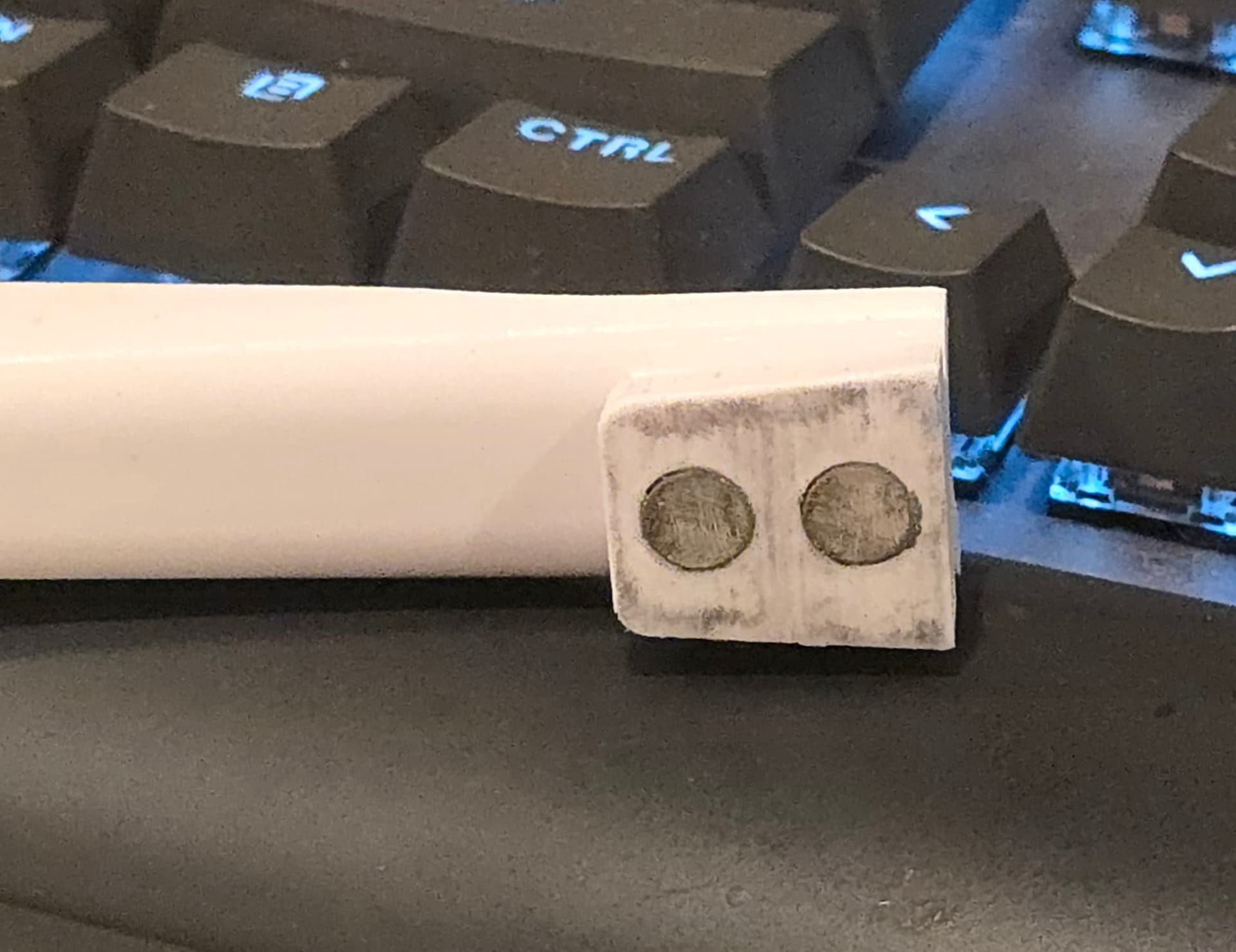
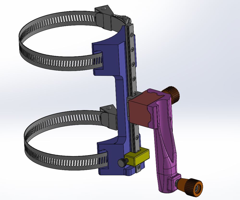
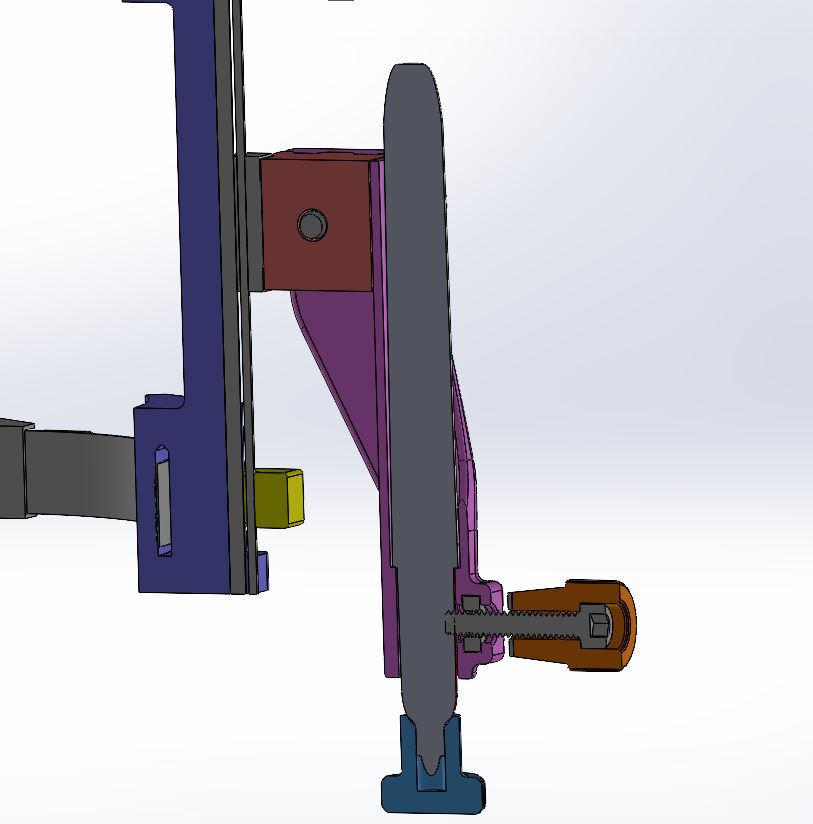
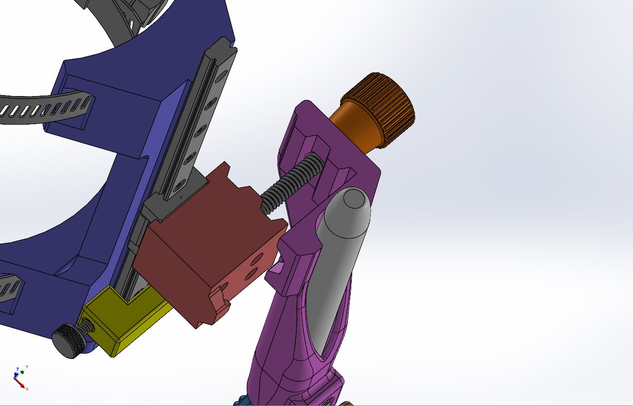
I plan on printing multiple pen holders so that I can easily remove one and drop in another one and continue on. The pen holder will be held in place with both the keystone tapered mounting boss, and Neodymium magnets, so theoretically, the swap over should be quick and painless.

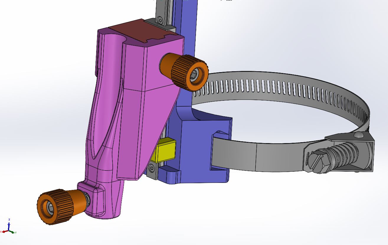
The yellow slider is for setting the bottom of travel for your pen, because there will be a lot of variation in mounting location, spindle height, stock height. . . so being able to set the lower limit of travel will be nice, if you need it.

Other holders can be designed to accommodate other sized pens / pencils, or a sleeve set can be designed for smaller diameter pens / pencils to be held properly centered in the holder. Whichever seems to make sense. Maybe a little bit of both? Let me know.

5 Likes

You should make yourself a tool length setter that seats your pen carrier and has a hard stop for setting each pen to the same stickout.

Here is a crudely drawn example.
Lets you ensure all pens have the same effective length without having to mount on your machine.

3 Likes

Well, for the most part, things went pretty well. A couple of small changes to be made, but nothing drastic.

Usually, my 3D prints tend to be just a bit oversized by 0.01" or so. Oversized, but in the “drawing outside of the lines” manner. Like, 1" cube may measure 1.01" on sides, but 0.5" hole in the cube measures 0.49", so I usually just add or subtract that 0.01" as needed to the dimensions to get that fit I am going for.

Well, this time, that didn’t work out so well for whatever reason.

This is the gap I had set up for the keystone boss for the pen holder. 0.01" gap on each side. I figured it’d be a good fit.

Sad Trombone Noise

It was not a good fit. Oh well, the good news is, I can modify the small part and reprint it in about an hour. Also, being that it is tapered, I can slightly undersize it this time and if it does not seat all the way at the bottom, that is fine, as long as it is 85-90% down, that should be good enough.

Also, the holes for the linear rail line up nicely, but again, due to the 0.01" over/undersize, they are a bit too small for the thread forming tap to do its thing. It just gums up and rips the plastic out instead of forming it.

And I have to reprint it anyway, because I made a rookie mistake and forgot to tell the slicer to not put supports in the curved channels, so they are clogged with support with no way to get it all out.

Overall, not bad for a first go. A few small changes and I’ll be printing a new iteration shortly.

1 Like

Well, believe it or not, I actually worked on this over the holiday break. I adjusted the dimensions for the interface between the pen holder and the receiver that mounts to the linear bearing block.

I also designed a small Sharpie cap since the regular one will not fit when the pen is in the holder. I tried the fit on 11 different Sharpies I found around the house, and it fits them all with varying amounts of tension, but nothing too tight or loose.

The interfaces look like :poop: because there is some play even when they are supposed to be locked together tight. I tried sanding down the surfaces / magnets to get a better fit, but it’s just not going to happen.

I think I will switch to a vertical V notch interface with a screw to pull them together. I’ll hopefully have something mocked up by tomorrow afternoon.

Anyway, overall, the design is functional, and probably more rigid than what I was /am currently using, but I want what I want, and I want more rigidity, so I am going to keep fiddling with it.

3 Likes

@MadHatter

Pretty cool design there!

1 Like

Could you use a magnetic pin or ball bearing to more positively lock the holder in place? I’m thinking something like a v groove wherein the magnets in the interface pull a ball and seat it just under the diameter of the ball bearing.

Think something like a ball detent or kinematic constraint. It should automatically provide positive locking while still being “breakable” when going to remove the pen. (Maybe an integrated flexture in the 3d print you could press to break the magnetic hold on the ball :man_shrugging:)

Tool less changeover is convenient enough to warrant a lot of additional experimentation in my opinion :slightly_smiling_face:

Looking good so far though, I’ll be ordering the linear rail today.

1 Like

I was able to get the new mounting interface designed today. I switched out the heat-set inserts for #10-24 stainless steel square nuts, since those are cheaper and easier for most people to use. No soldering iron needed, but you have to pause your print and drop them in, so a little more work than hitting print and walking away.

The pen holder will end up being more rigid with the panel running most of the way down the side, and I also swapped out the thumb studs for 3D printed thumb collars that can have #10-24 SHCS epoxied in to make them. I prefer stainless, but whatever you choose would work.

I decided to add a locking lug on the left side of the pen mount as well, to help reduce any deflection. We’ll see how well it works. I will probably have to play with the dimensions to get things to lock together tightly, but I should be able to do it with the screws instead of the magnets. Also, the layer lines are now parallel to the mating direction. The previous design had the mating direction perpendicular to the layer lines, which caused binding instead of being able to seat tightly.

2 Likes

This topic was automatically closed after 30 days. New replies are no longer allowed.