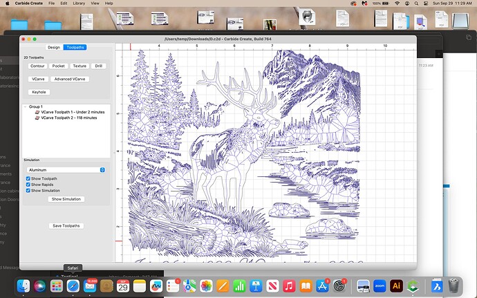
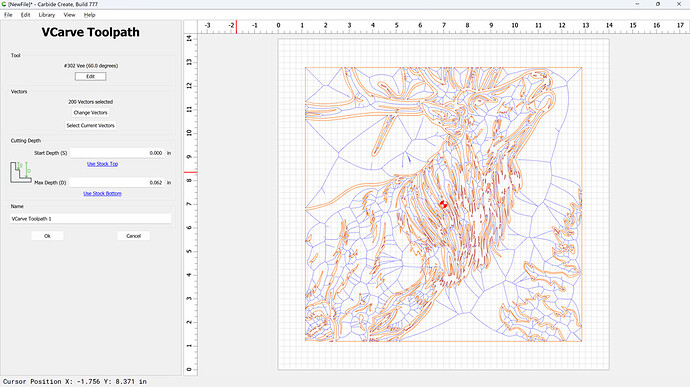
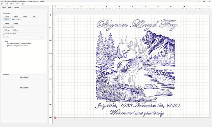
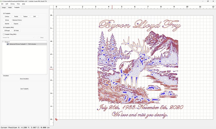
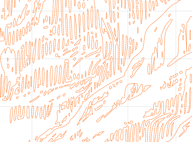
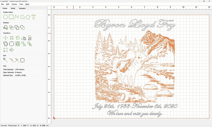
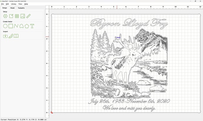
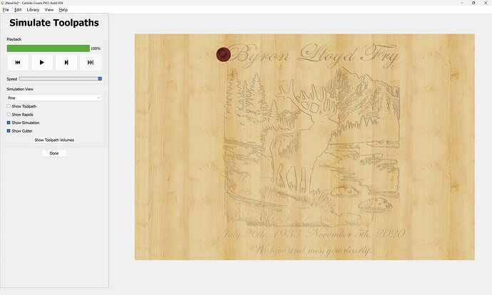
Purple lines show up in pathway, they aren’t in design. Would like to machine without the purple lines.
Magenta lines are not closed vectors. On a busy picture like above you have to zoom in a lot and clean up open vectors. You can do that by deleting unwanted objects or by using the edit nodes or maybe closing with the edit node tool.
When converting bitmap images sometimes you get double lines and you would need to delete them or you get a small pocket.
You have chosen a V carving toolpath which cuts along the center of a design.
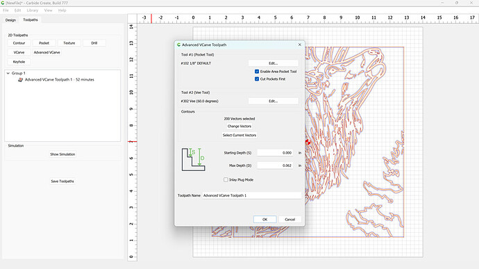
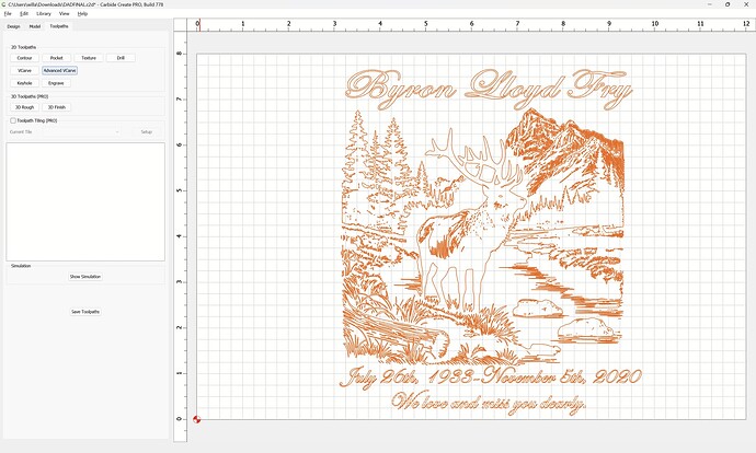
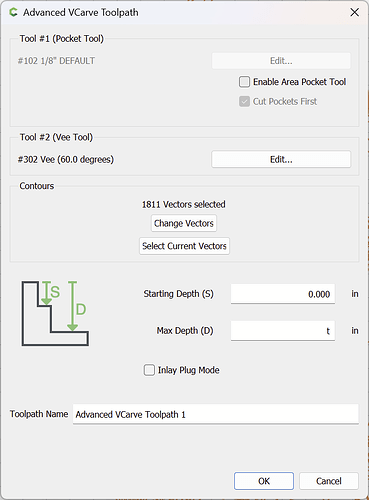
Use Advanced V carving (or try the v8 beta).
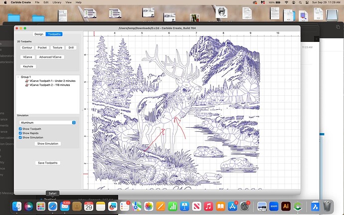
I see you’re using v-carves. Are you talking about the lines I highlighted (see attached pic)?
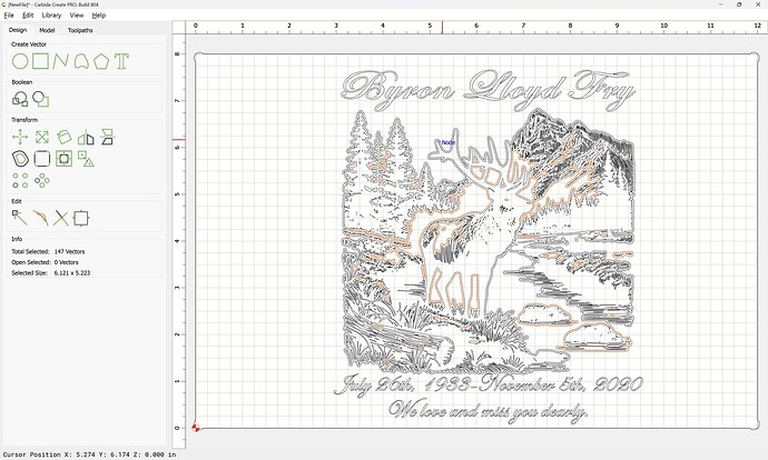
If so, those are just the tool paths. CC is showing you where the tip of the v-bit will go to make the sides as wide as the selection. Think of it showing you where the bottom of the valley is, with your artwork lines being the tops.
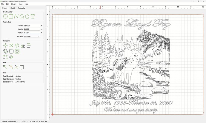
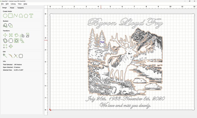
If you look at the elk, there are boxes within the body, also around the entire image. The boxes don’t show up in design, they aren’t meant to be part of the drawing. When looking at toolpath, the boxes show. The cnc also cuts the boxes. I’m a novice. I’m not certain how to correct the image, not cutting the boxes on the elk and other places in the background.
What bit are you using? The boxes are showing where the bottom of the v-bit will go. You can tell because they run between each of the details in the design you want to carve around. It’s carving out all the area between the image - leaving the image at your top depth.
Do you want the elk details (purple lines of the original image) left uncut and all the empty space (white areas) carved lower? That’s how it’s showing now. How deep do you want each hollowed out area? You can set that in the toolpath itself in advanced v-carve. But in a regular v-carve the point of the bit will go as deep as it needs for the sides of the bit to reach the design edges that remain.
If you want to post the file we can take a quick look and maybe help you get what you’re looking for.
Don’t upload a picture of the project. Upload the project, so we can look at it properly.
We can’t help you if you don’t provide the info we need.
At the risk of stepping on WillAdams…I was just watching football and thought I’d try to help a bit…
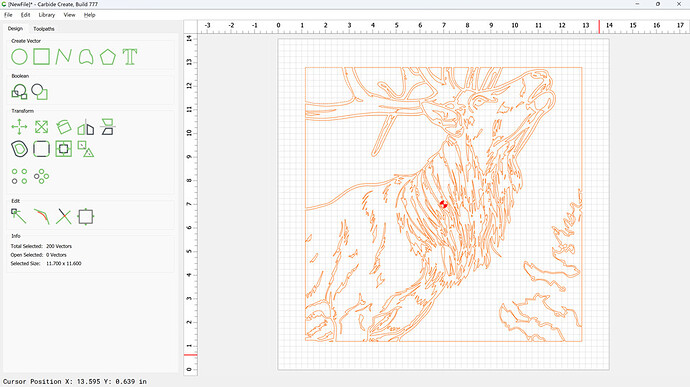
Not knowing what you’re exactly trying, but guessing, I started with a generic image I found online. I did an image trace in Carbide Create and put a frame around it to give an edge to the image.
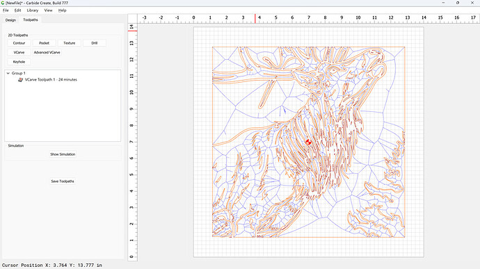
Selecting the image and a v-carve toolpath produces this (what you’re getting):
You can see the blue “boxes” that show where the bottom tip of the v-bit will go in it’s effort to carve the design. Depending on what is set as the depth of the carve, the v-bit will only go that far when it cuts. The depth of cut (left over from my last project) was .062 inch.
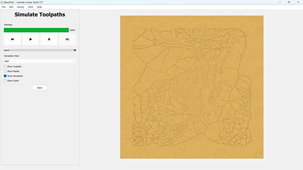
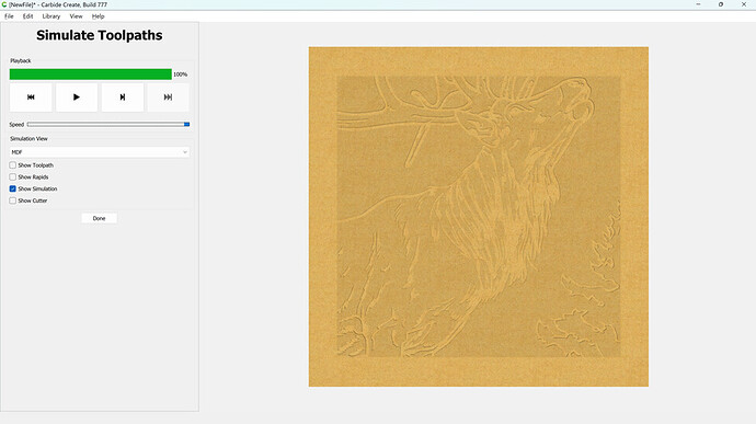
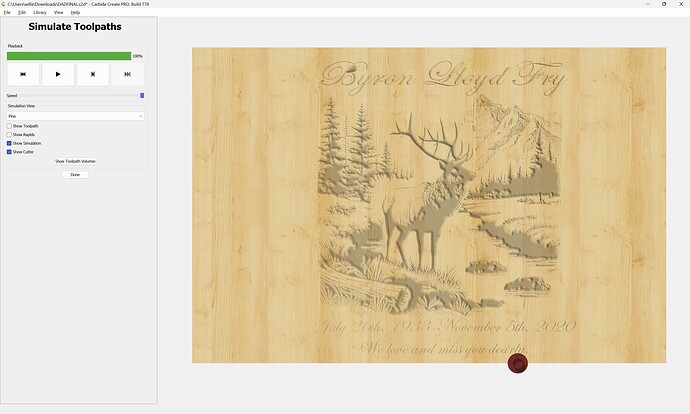
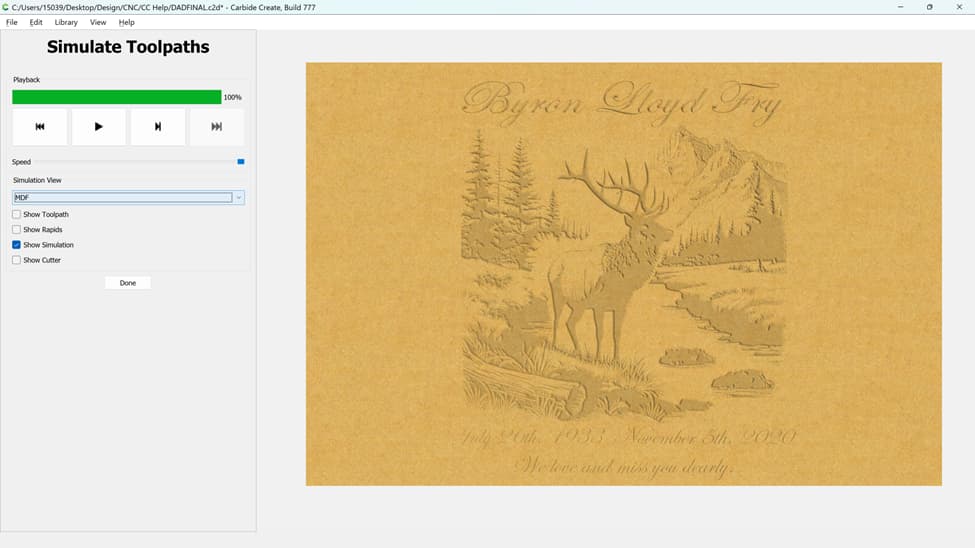
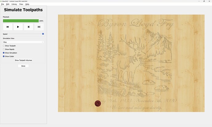
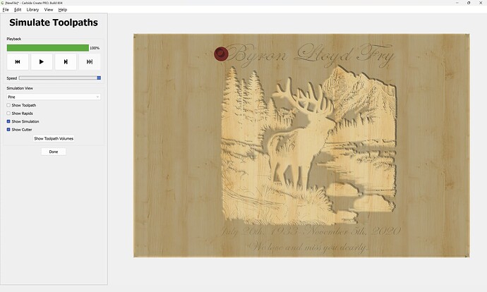
That results in a simulation that looks like this:
Probably what you’re seeing in yours. The v-bit tries to go deep at the tip so the sides of the bit reach the design. But the bit empty spaces would need a LOT of depth for the sides of the v-bit to reach the edges of your design.
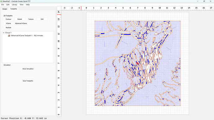
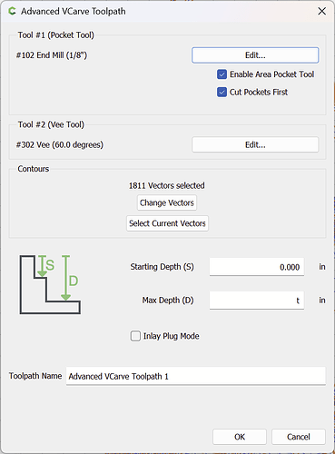
So, here’s an Advanced v-carve of the same design (using an endmill to take care of all the big spaces):
The simulation looks like this:
The elk and antlers remain the original height of the material and the empty spaces are .062 inch deep.
Is this more what you’re looking for? If so, you can do some editing to get the time of cut down. I didn’t adjust anything, change to different endmills, etc. so the cut time of this example is big. But, eliminating a lot of unnecessary detail, etc. can certainly reduce the cut time. I hope this helps.
Dave,
What you have shown is exactly what I am trying to achieve.
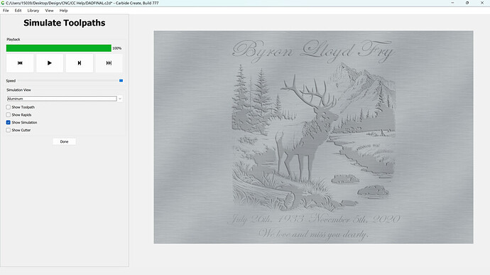
Thank you. I had bad luck with the bit you selected, several broke and the fine detail was not achieved. Cutting in walnut so the material isn’t very dense. Next cut will be in aluminum for a temporary piece while the granite is being completed.
File attached as requested.
DADFINAL.c2d (3.8 MB)
V carving is intended for wood, not aluminum.
Thank you for the in depth explanation. I reworked some of the parameters but I’m still getting the blue lines, even with the adjustments.
Any chance you could look at the file I uploaded and set some parameters, make some suggestions?
DADFINAL.c2d (3.8 MB)
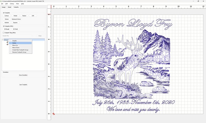
You are still using V carving toolpaths:
Delete them:
Select everything:
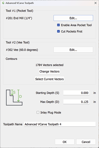
Choose “Advanced VCarve”

“Use Current Selection”
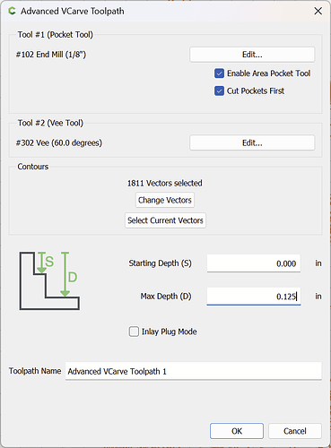
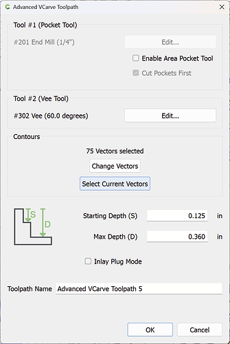
make appropriate selections:
including setting the Max Depth:
Concerns include:
- tool selection — the 30 degree Amana is defined as an Engraver, not a V tool
- setting Max Depth and other parameters
- overlapping geometry — see: Merging Script Fonts in Carbide Create V6
- figure ground reversal: Figure ground reversal and Figure-ground reversal and toolpath considerations
which previews as:
First, we fix the geometry…
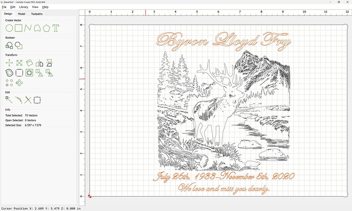
Hey Doug. Took me a bit but I took the liberty of converting your toolpaths to Advanced V-Carve. This is what the simulation looks like now:
I used the time to clean up the text. There was a lot of overlap in the letters - it’s just how some fonts render. But, Carbide Create and Carbide Motion just see lines to cut. So all the extra lines between letters may gerk up your final product (yes, gerk is a technical term). It’s for your dad so it was worth it.
As you can see, the time CC says it will take to carve (at the shallow depth I have set) is 1477 minutes (or over 24 and a half hours). That’s a lot, especially since the Create estimates are less than the Motion estimates which are just estimates anyhow and are less than reality.
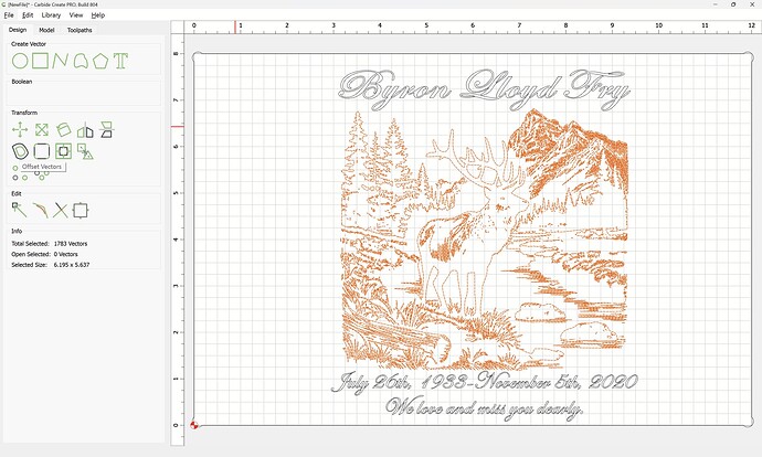
To fix that, I would look at the artwork in the center. The image alone is over 1800 vectors. Think of a vector as an individual shape (Will may correct me, but that’s my layman’s version). Here is a look at the mountains in the top right corner:
and a zoomed in look at that piece:
Each one of those is a vector the bit is working to carve around. You could probably delete half to three-quarters of the vectors in the mountain alone and still have a great image when you zoom back out to the full image. Take a look at that when you can and you’ll see you can remove a BUNCH of work for the machine, which will reduce your cut time significantly and still give you a great memorial to your father.
I tried to upload your amended file but I’m limited to 4MB. The file is 4.14MB. If I can figure out how to get you the file, I’ll do so. I’ll try messaging you directly and if you’re willing to share your e-mail, I’ll send it to you that way.
Best of luck!
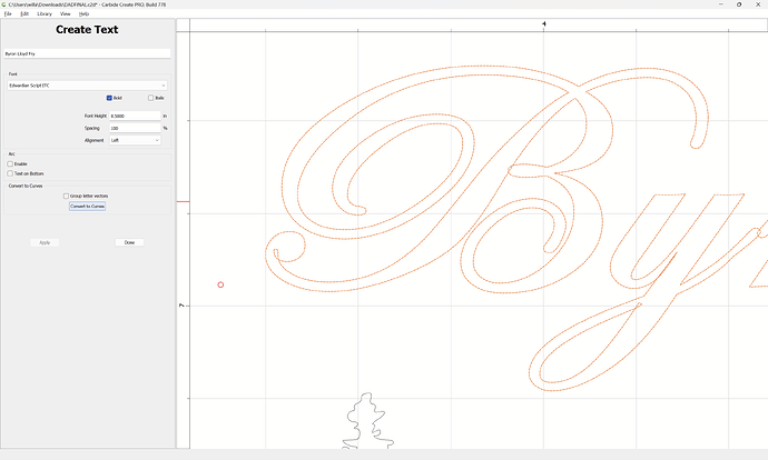
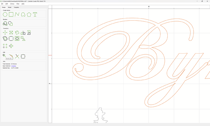
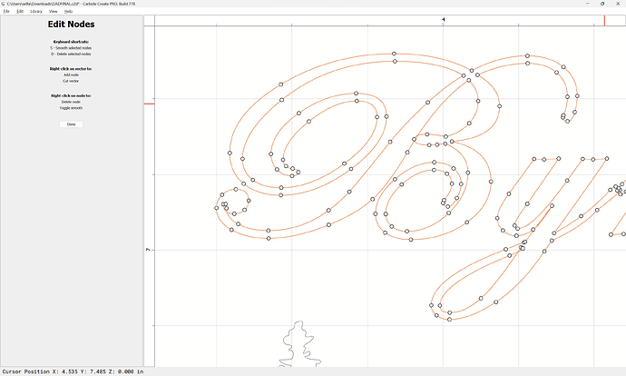
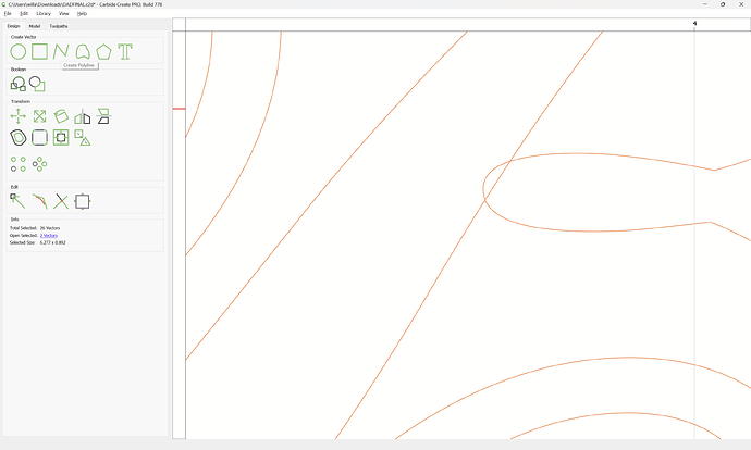
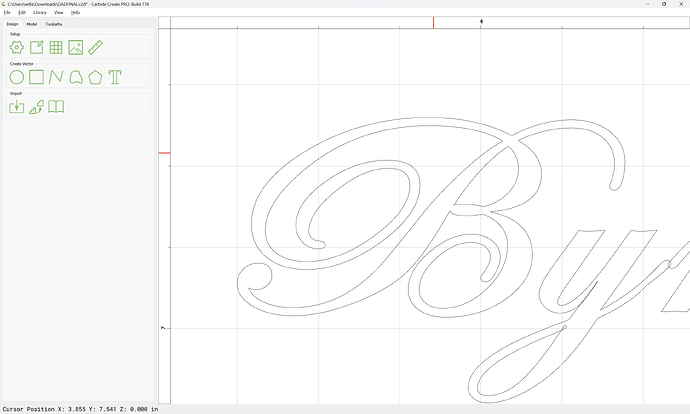
The odd carving of the counter in the B is caused by an overlap:
So we Convert to Curves:
and then Node Edit:
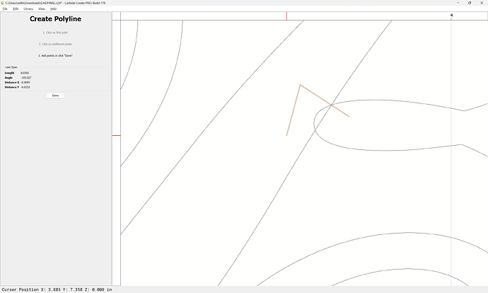
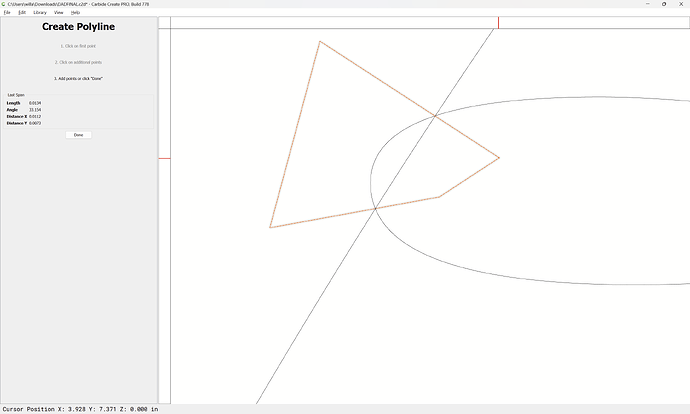
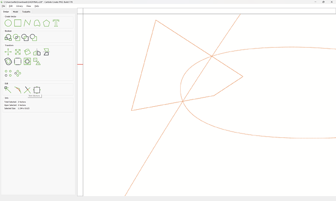
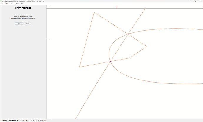
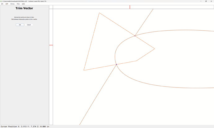
or, use Trim Vectors after drawing in additional geometry:
Trim Vectors
and Node Edit and so forth until one arrives at:
Repeat for any other self intersections and so forth until one arrives at:
but probably the most expedient way to address this is to begin by cutting the design itself proud:
and then V carve the text at the bottom of that pocket:
Alternately, offset the design:
Apply
Keeping only the outer geometry
and then only V carving everything at the surface:
Attached as a v8 file:
DADFINAL_v8.c2d (3.1 MB)
This topic was automatically closed after 30 days. New replies are no longer allowed.
