I’m trying to set up a PCB which has dimensions of 6.9" wide by 4.2" high.
The BOTTOM file imports fine.
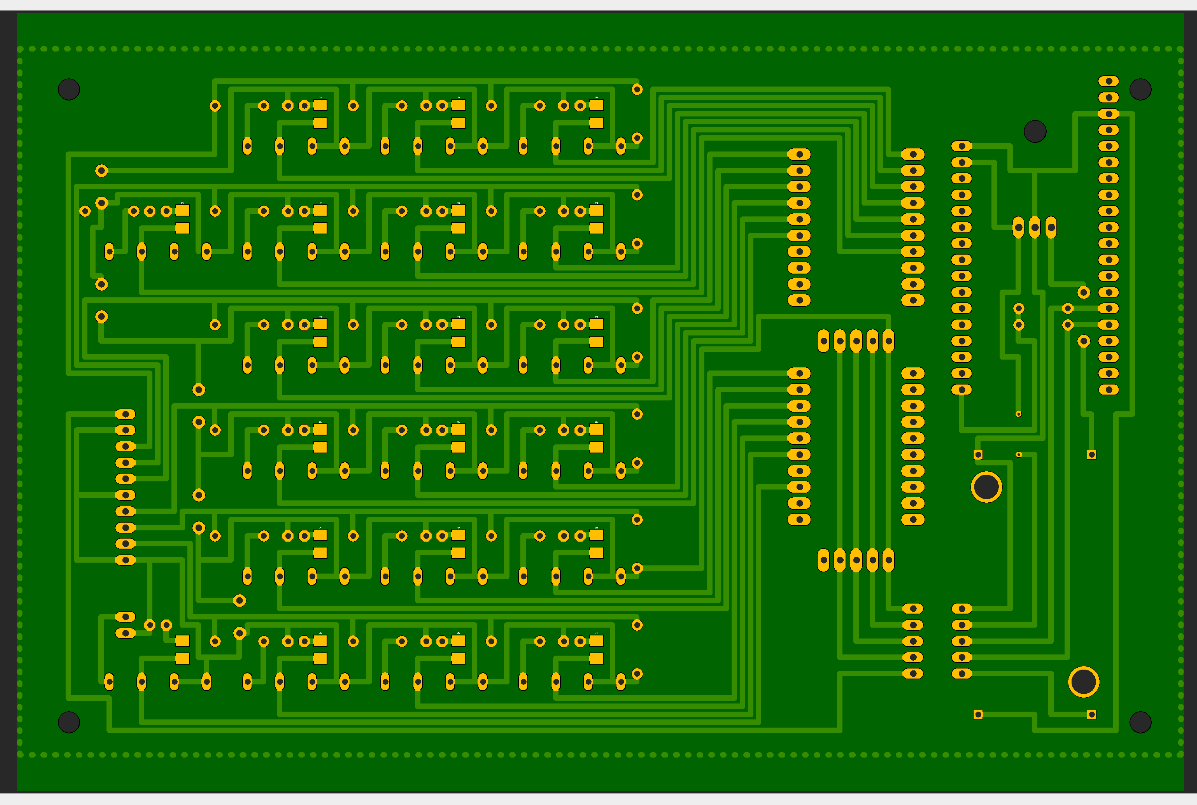
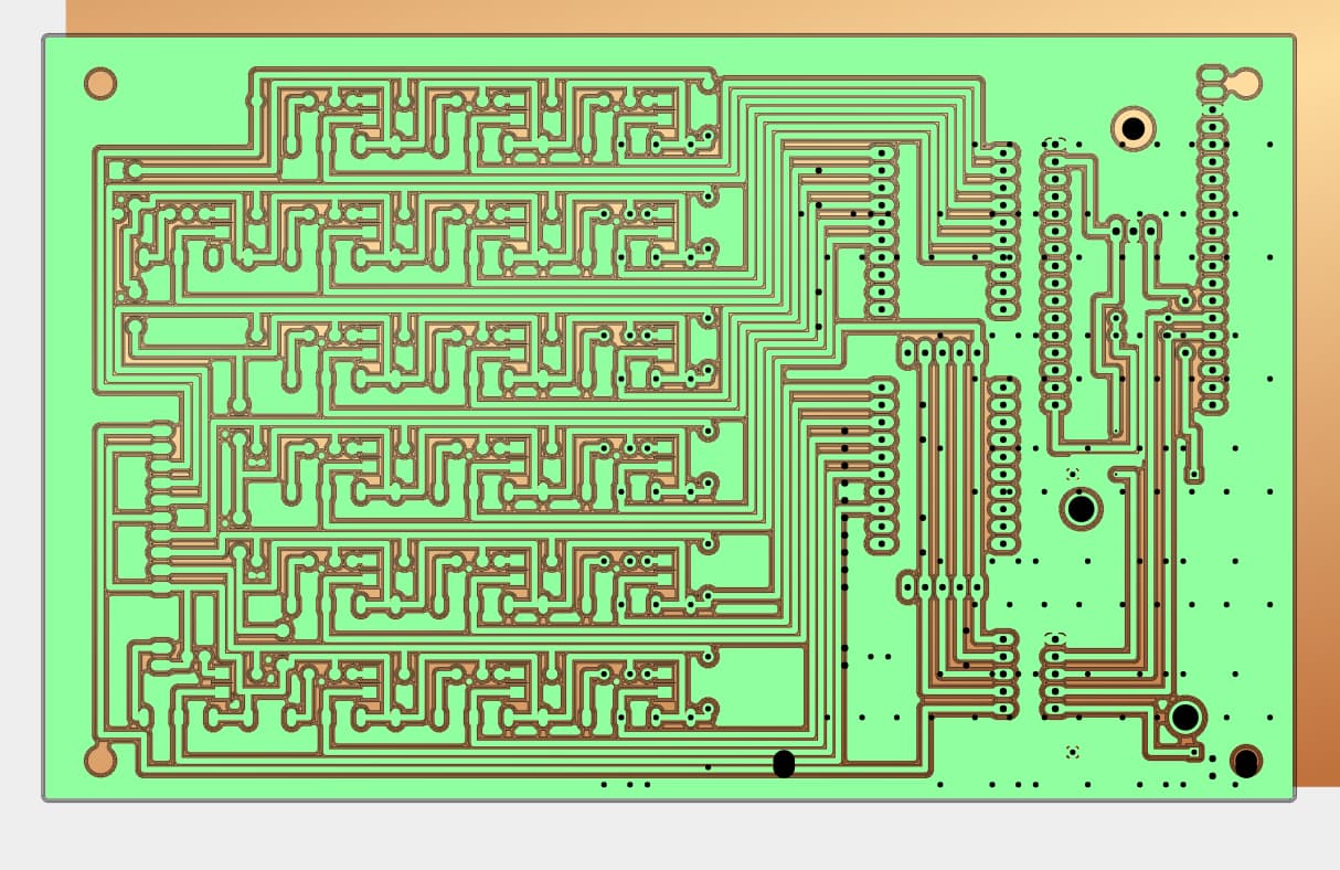
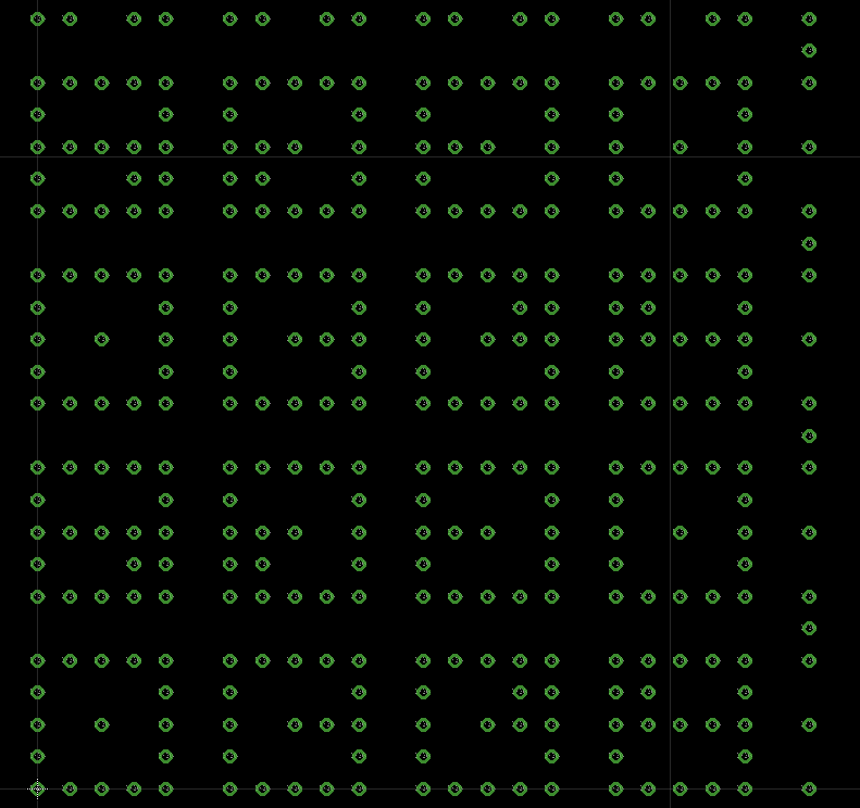
When I preview the board in Eagle’s MANUFACTURING tab, the board and holes are all visible and correct. Likewise with the Gerber Viewer at PCBWAY…looks fine:
I tried metric and imperial and got the same results with the holes “wrapping”.
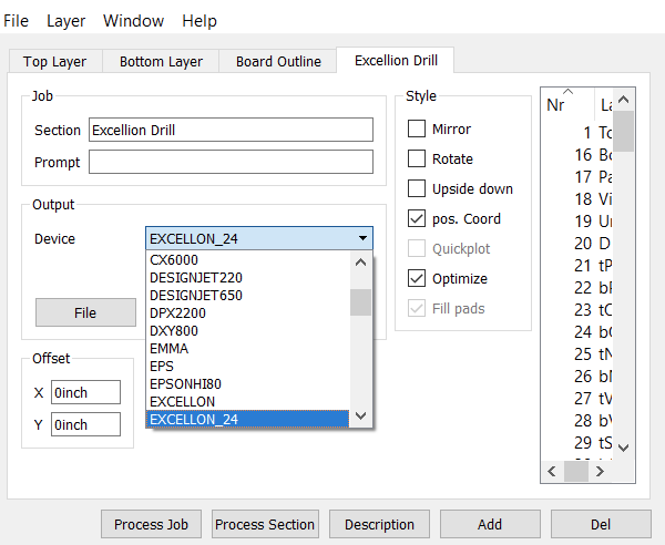
I did not see any option in Eagle to switch the type of drill file format. I can check again.
However, the preview in Eagle shows the board as being correct. It is only when it is brought in to Copper that the holes “wrap”. This is definitely a Copper bug, not an issue with the output format of the file I think.
What should I do next to provide you with the information you need?
Thanks fo the dialog boxes for the Excellon control. I will check those out. i’m using Eagle 9.6.x on Mac, but I am actively switching over right now to Fusion 360.
The origin is in the lower left corner of the board when viewed normally in Eagle. But as these PCB screen shots are showing the bottom of the board, the origin is flipped so is at the lower right corner.
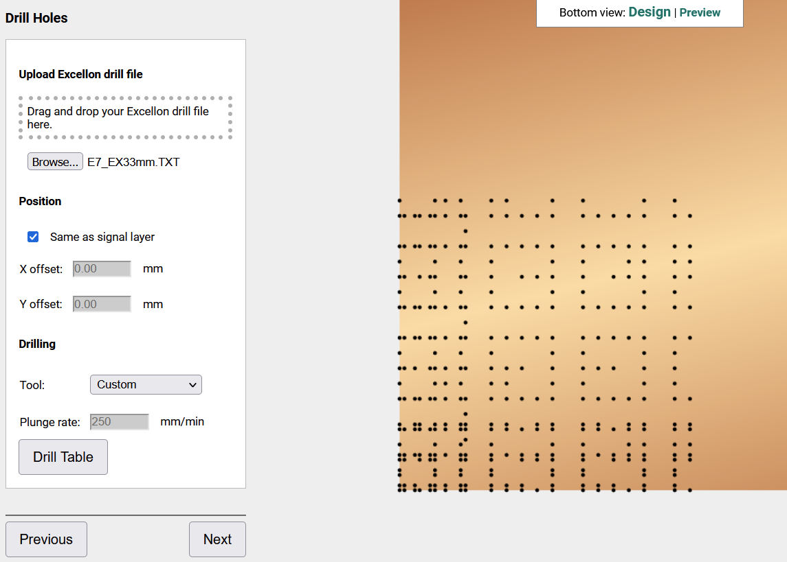
It really looks like they are confined to a 100mm x 100mm area so this may
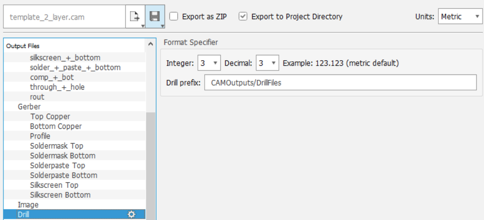
be related to the bug I posted. This is what happens when I export Excellon_33mm
and import with Copper in mm mode: