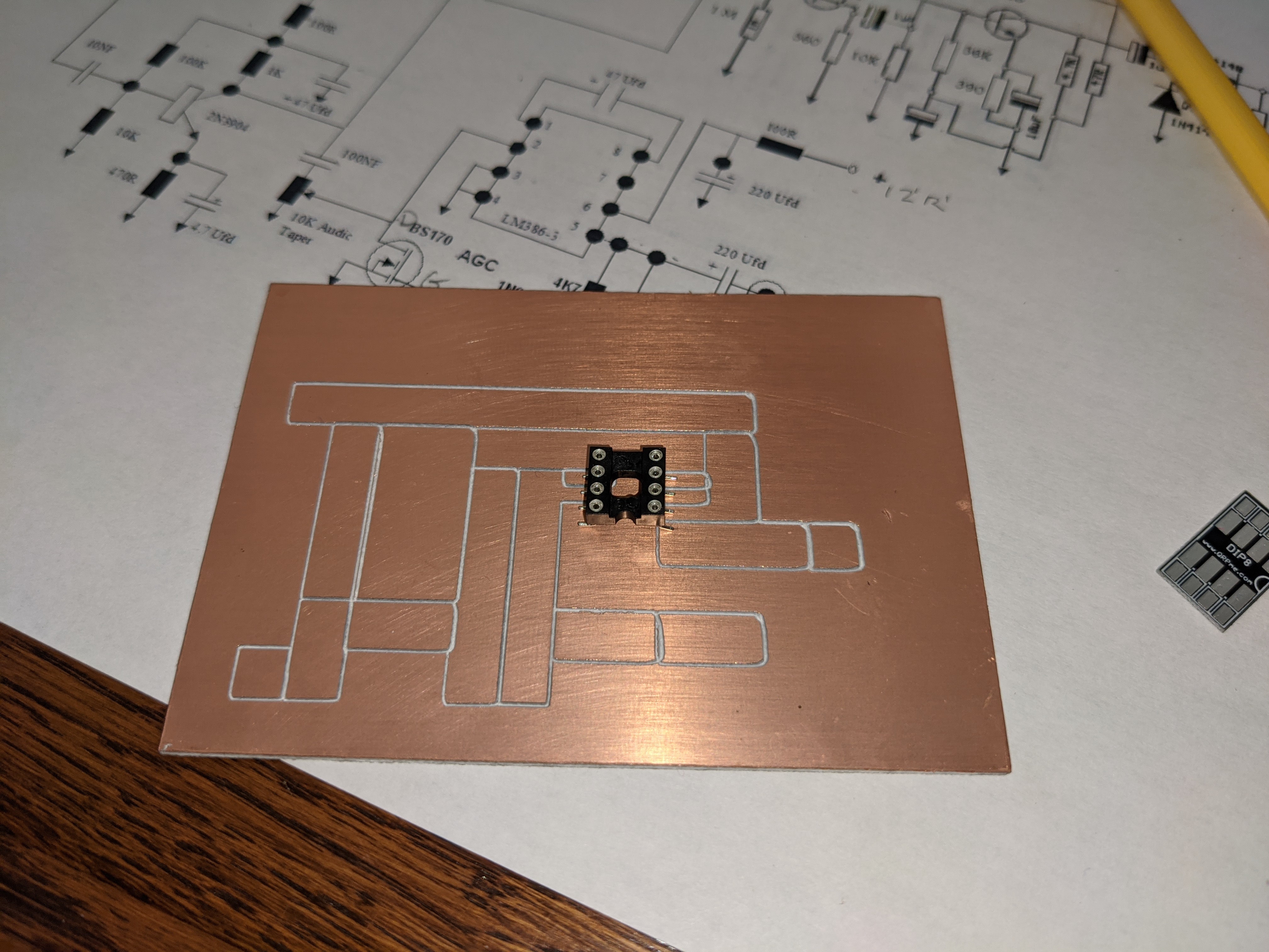
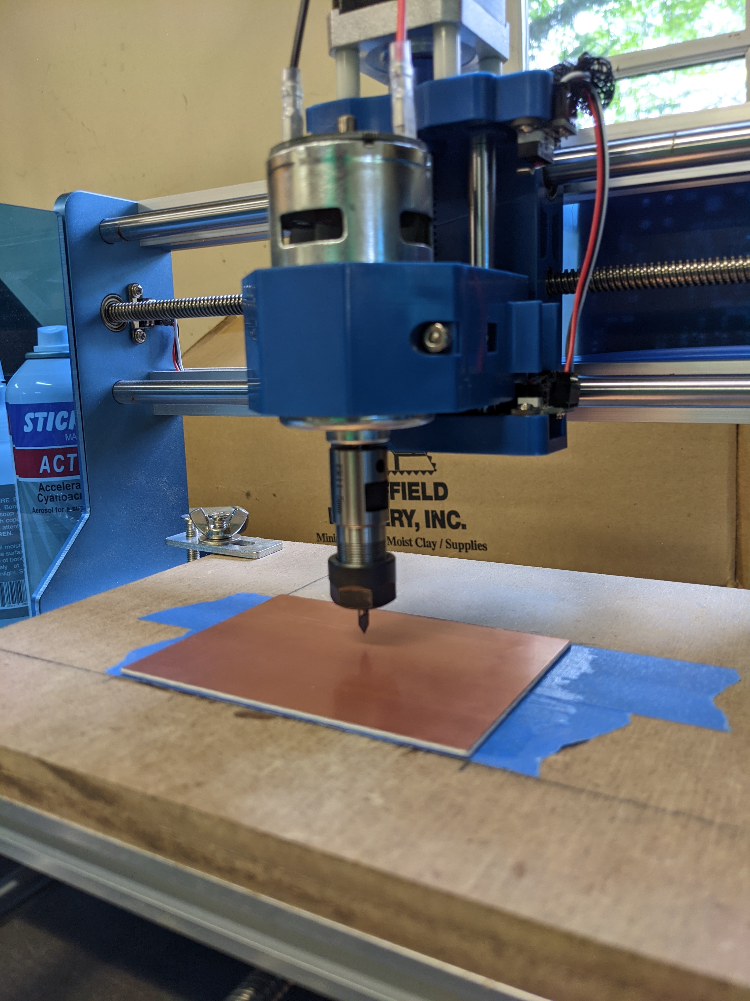
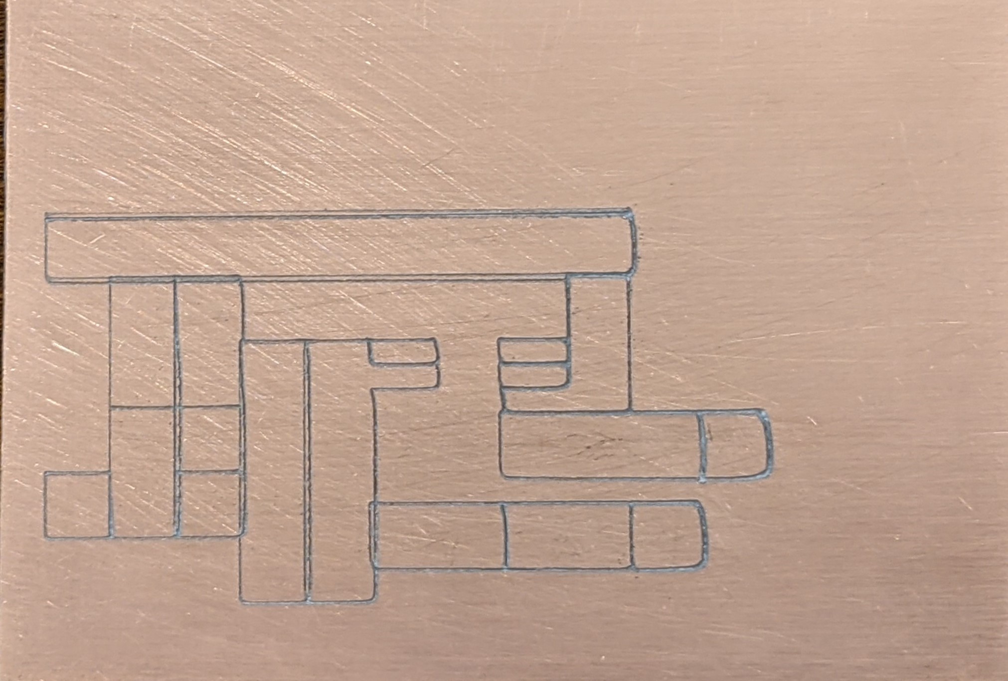
Hi all - the project is PCB milling for a homebrew ham radio project. The shapes are a series of adjoining rectangles each snapped to the same grid line. Each rectangle is meant to be an island of isolation with no continuity between the island and the rest of the board - so I just need to cut through the copper. The job settings are as follows - 60 degree V bit. Contour Tool Path with no offset. Max depth .250 mm, depth per pass 0.083 mm, feed 150 mm/min, step over is 0.15. It appears to me that Carbide is creating a tool path for each rectangle separately and not accounting for the overlapping edge. In other words with my current settings there should be 3 passes, but the common edge gets 6 passes. Is there another way I should be doing this?
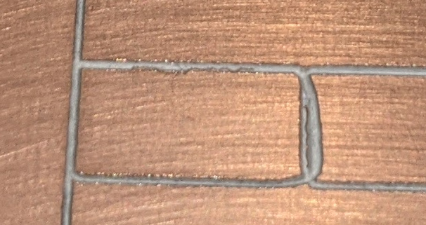
You can see that the overlapping edges appear to be wider groves than the single edges. Any help or suggestions for a different way to do this would be appreciated.
One suggestion to in CC to blow (zoom) up your images to make sure they really are touching. Secondly maybe try boolean to join all the squares/rectangles together a few at a time joining larger and larger blocks together so there is no overlap. But my first suggestion is likely to show any sides not touching.
I’m with @gdon_2003: make sure everything is perfectly lined up and then boolean join everything to make this a single vector that the contour toolpath will follow.
Can you upload the c2d file ? The rounded corners and the specific close-up below tell me that you may want to check the machine mechanically too:
Thank you for the advice. This is one of my first projects, so I am still on the steep edge of the learning curve. Thanks for bearing with me. The .c2d file is attached.
First - Boolean Join - I honestly didn’t know about the Boolean options. After reading your notes I tried to use it but I clearly don’t understand it. Simple example - two rectangles with one adjoining edge. If I select both of them I get three options -
Boolean Union - makes the adjoining edge disappear so I get one, larger rectangle.
Boolean Intersection - makes both rectangles disappear.
Boolean Subtraction - makes one rectangle disappear.
I do not get an option called “Boolean Join”. Any additional advice there would be terrific.
Second - I carefully used “snap to grid” to make certain the edges were truly truly on top of each other. Zooming in only shows one line at each edge.
Third - possible mechanical issue. I noticed the curved corners as well and was wondering about that. My CNC is not a Carbide. It is a SainSmart 3018 PROVer. There is no belt. I’ll have to look in to what set screws may need to be tightened. I understand this forum may not be the best place to ask for help on a non-Carbide machine!
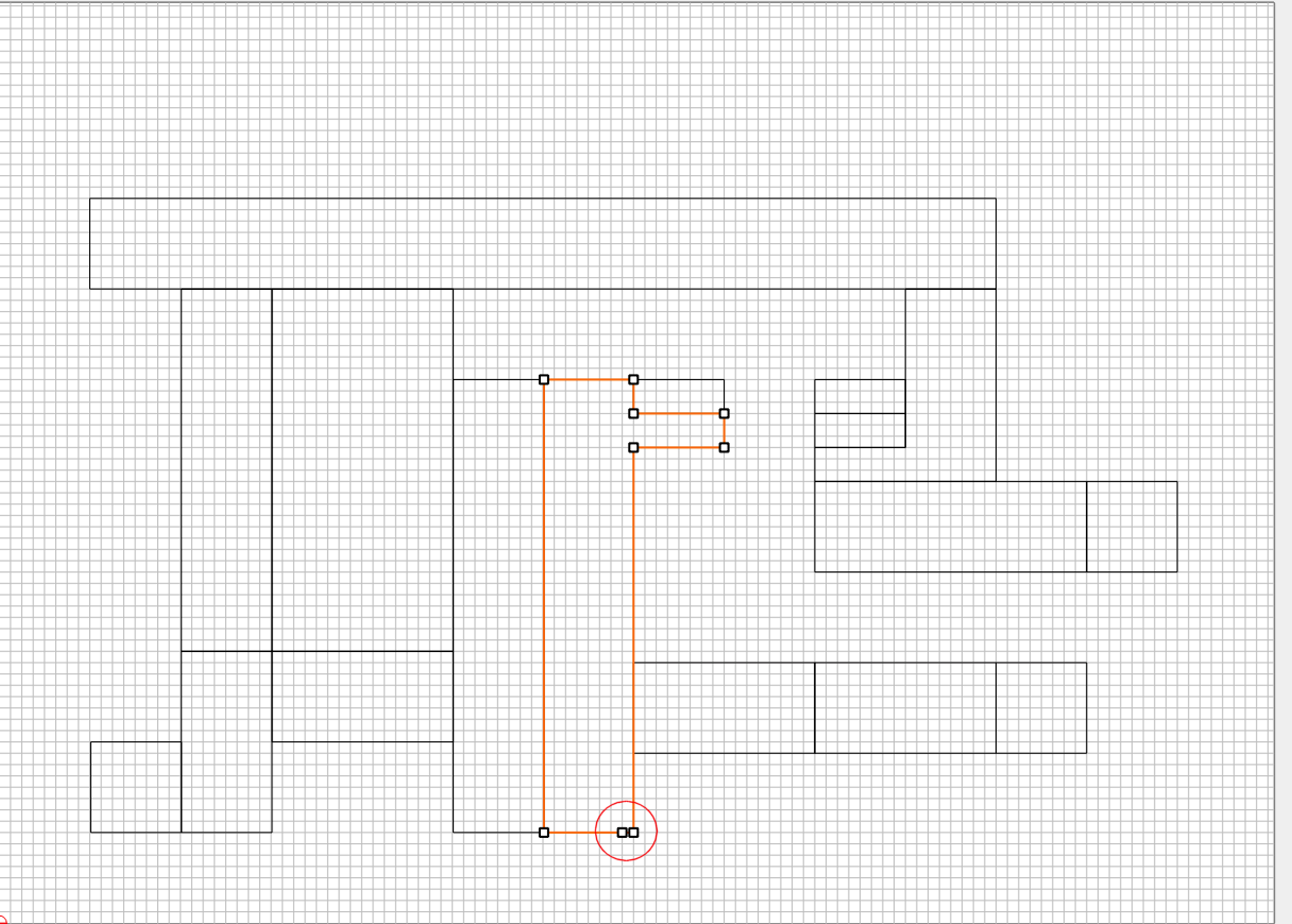
Had a similar problem once and found that extra nodes between corners was causing some confusion in the gcode. I didn’t look at all of you island rectangles, but did see this one:
Good thought… I would imagine if this was the case, if the design was run with a really low feed rate it would scribe a different path, no? An easy test to see if it is machine or gcode.
Thanks for the advice. Sorry for being dense. I am very new at this. Where are the anti-backlash nuts located and what do you mean by “dropping”? I looked through the manual and parts list and did not see anything called an anti-backlash nut. And then once I find them what is the remedy?
I can definitely redraw that path to eliminate the extra node. But the curves are happening other places where there are no extra nodes.
Gerry - not sure what you mean that running the design with a really low feed rate would scrive a different path. Why would that be and what test are you suggesting? What do you mean by really low? I’m still pretty new to these concepts.
The brass nuts inserted into the carriages (X and Y) that have a spring to hold them against the pitch of the screws. The plastic portions of the carriages aren’t always well formed and the nuts can drop out or shift allowing backlash to occur. That’s when the rod spins but it takes a fraction of a rotation for the motion to transfer from rotary to linear. In the most severe cases the nuts come all the way out of the carriages.
With the power off and holding say the X carriage, try rotating the threaded rod by hand. If you can feel it move but don’t feel the motion transfer immediately to the carriage you may have found the problem. Likewise the Y axis.
Disassemble and inspect as necessary. Possible solutions are epoxy, replacing the nuts and/or spring. Check out the various 3018 groups on FB and elsewhere for more information on cures.
Very helpful. Yes the SainSmart 3018 PROVer comes with the carriage pre-assembled. Everthing seems pretty tight, but I will check it out,
I also found that I can insert the bit much further into the collet than I I had before - in case it is bit deflection that is causing the issue. The learning curve is steep but I am picking up a lot.
I appreciate the friendly and very helpful responses.
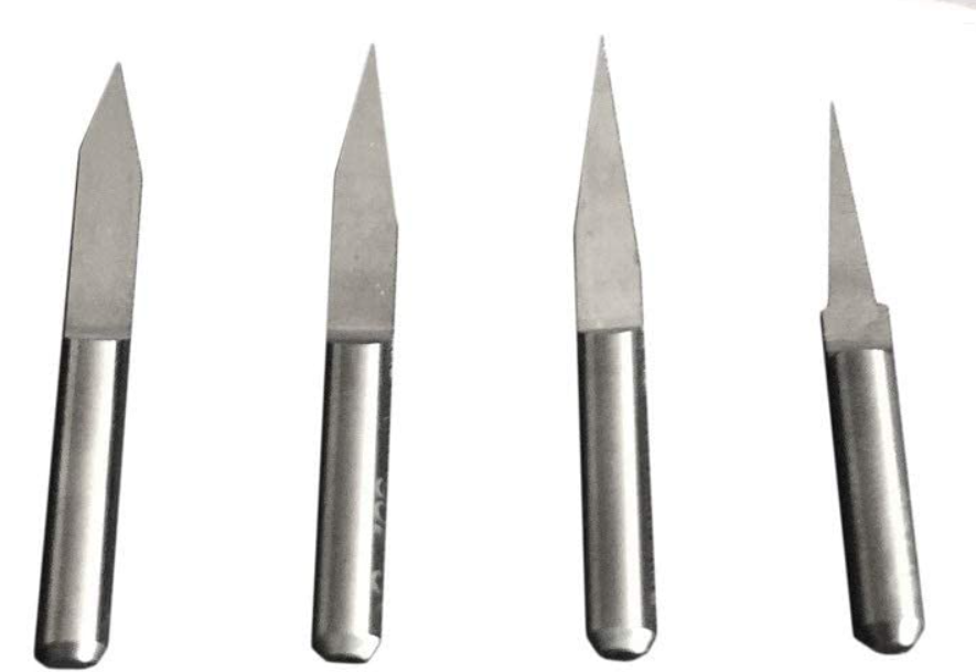
You should have the shank of the bit all the way into the collet except maybe about 1/16" of an inch before the “V” shape begins if you are using ones like this :
So next challenge - with the bit properly inserted there is insufficient Z travel to reach the work! I can use a thicker spoiler board - but then screws with the T-nut clamps supplied with the machine are too short to clamp down the spoiler board.
Off to Home Depot for a hardware run. What do others use for clamps? I suppose I could also use tape and glue like I’m doing with the PC board.
If backlash is the issue, then when either axis screws change rotations, there is a moment where the spindle mount is not responding to the screw’s change in direction but is waiting to meet up with the other size of the inside of the screw. A spring assembly is usually used to force the surfaces to always be in contact with each other (ie: an anti-blacklash nut).
It might be possible that if the spindle is moving rapidly, then its inertia could make it flip a tiny amount to the other side of the screw and offset the path… like writing when you aren’t holding the pen very tightly, it might cause straight lines to have curves or deviations… though perhaps not to the extent shown in your photos.
If this is the issue, then maybe if the inertia is reduced by slowing things down, the spindle won’t slam to the other side of the screw and this wobble will be reduced and a different path scribed. Just an idea, anyhow.
Got it! Thank you. That makes sense. I have several things to look at now. I need to take a stepwise approach an eliminate variables. Basic principle - only change one thing at a time. First thing I know is wrong is I had the bit way too far extended. So, I’ll fix that and see. Then turn to speeds. On thing I observed is that there is no obvious backlash effect if I turn the axis screws manually - it all seems pretty tight to me. But I will take it one step at a time.
Also check that the setscrews in the couplings between the steppers and drive screws are tight, they have tendency to loosen up especially if one the screws isn’t in a screw thread. Add a little loctite blue (pull the screws first), green (works after installation), or even a tiny bit of CA glue to keep the screws from loosening under vibration. Also check that the linear rods end screws are tight, and give the machine a once over for loose screws or out of alignment parts. There was a bad batch of anti-backlash nuts that hit all the 3018 makers (not just one relabeled factory, it’s been copied a lot), the symptom will be one of the nuts (usually the spring loaded one) will pop out of the slot and the carriage will move freely. Not too likely in your situation but it’s a possibility. Also if the anti-backlash nut’s slot is a loose fit a little hot glue (which allows for some inter-nut movement) will fix it. Some have even stuck paper or other shims between the nut and slot. Mine had some backlash from the loose nut (the one in the machine, not behind the keyboard), but it took a 20x magnifier to see it after diamond drag engraving, so it may be pretty subtle.
There’s a very active 3018 FacePlant group (yes, I know, Zuck’s personal info harvester) with a fair number of Carbide Create users and PCB millers that might be of assistance. There’s several pcb to gcode tools that have been discussed there that may be a better fit (for specialized PCB milling, not general parts making) than the otherwise great Carbide Create.
Fabulous. Thanks so much for the detailed reply. I purchased the SainSmart ProVer after reading a bunch of reviews - expecting to avoid some of that pain - but I will definitely give the machine the once-over as you recommend. I’m active on the 3018 FB group. I find the dialog here much more helpful. But writ the SainSmart specific questions probably a better place to begin.
The discussion about machine tune-up distracted from my original question - on rectangles with adjoining edges, the adjoining edges have the tool pass over them separately for each rectangle - in other words it appears to treat them as two separate vectors even though they occupy the same space. Easy to see in the attached example. The boolean operators don’t help with this situation. Is there a different way to do this? For example should I just use line vectors instead?
I played in CC a bit and indeed things are not so simple as just using a little boolean sauce.
Once your machine is tuned it should not matter much that you cut some segments twice, but in the meantime what does work in CC is creating the outer closed shape, create a separate single inner line
I had reached more or less the same conclusion after some experimenting. So that will eliminate one variable in my setup. In order of easiest to test, my next test will be with the bit properly inserted, then feeds and speeds, and lastly mechanical issues with the rig. A cursory visual and manual inspection of the machine doesn’t show any obvious problems. Everything seems tight and square. So, one step at a time!
Thank you again to all who have taken the time to answer.
Thanks again for all of your suggestions and support. I adjusted the bit so that it is fully inserted. I had to lower the motor a bit to get enough travel in the Z axis, but everything is tight. I carved another board. As you can see I still have the problem - particularly with lines along the Y axis. Going from X to Y there appears to be some bit deflection. For this run - the bit is a US made carbide 60 degree V bit. Feed is 500 mm/min. Dep/pass is 0.083 mm, Max Depth is 0.250.
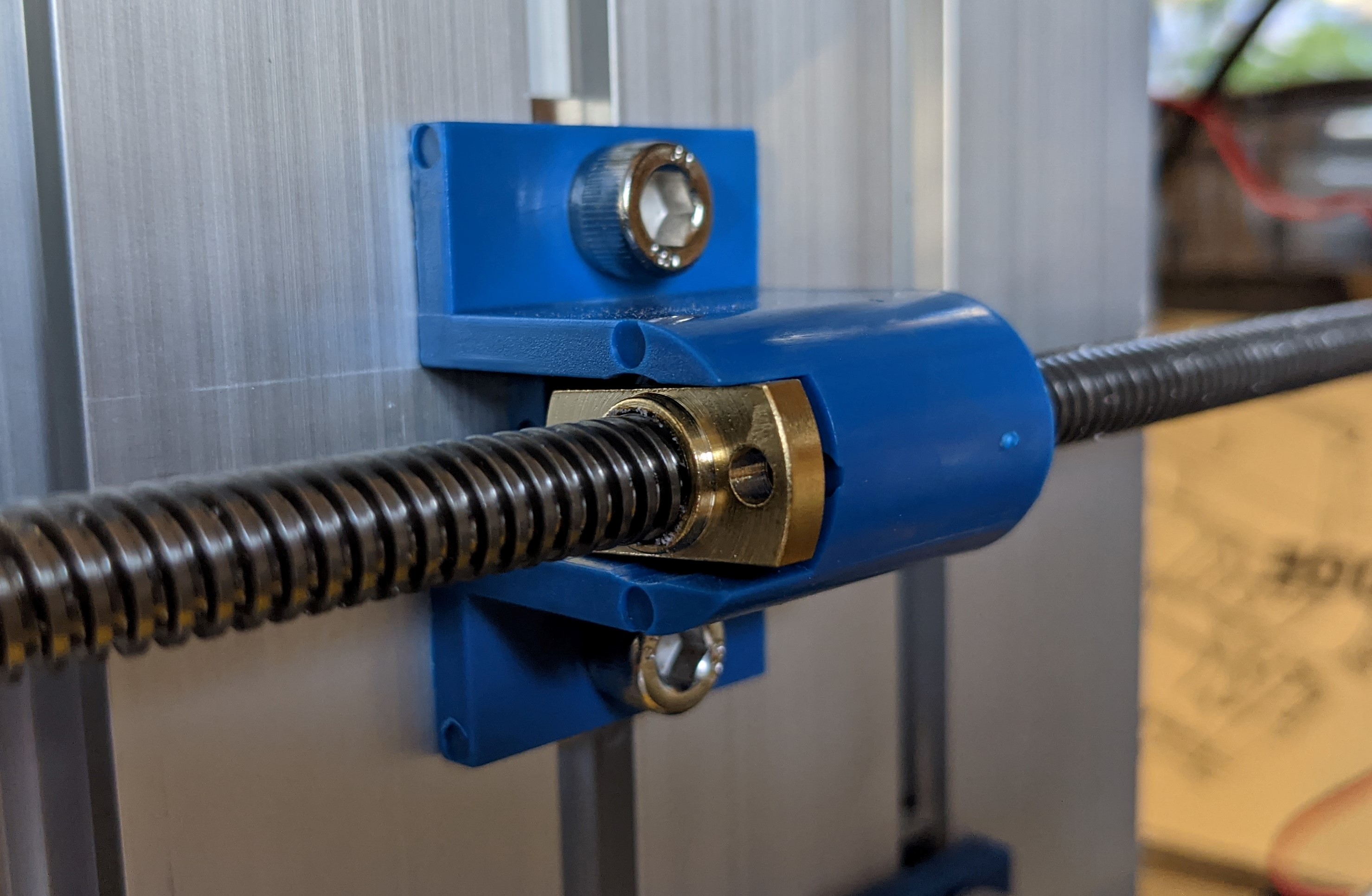
Pictured is the bottom of the carriage - y-axis mechanism. This came pre-assembled and I am not familiar with what it is supposed to look like. I observe that the brass fitting does not fit snugly into the plastic. When I rotate the rod by hand the brass fitting rotates a bit before it touches the plastic and I think there may be a a tiny delay between when the rod rotates and the table begins to move.
Any thoughts on whether or not this might be the problem or on any of the above?