It may still be backlash causing the problems. It appears too that things are cutting a bit wider/deeper on the far right than on the left. Have you confirmed that your wasteboard is level and/or run some skim cuts to level it to the Z axis? Is your Z-axis reasonably well trammed? Remind me too, how are you holding down the material?
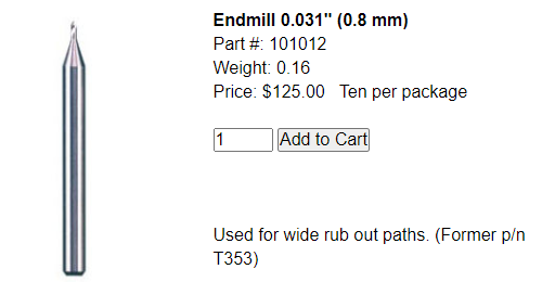
For reference, on machines made for cutting PCBs (https://www.lpkfusa.com/ for example) they typically use extra stubby endmills like this: which aren’t particularly cheap but work very well. I have a very old Protomat90 (1990’s vintage) that I keep running and it does a fantastic job.
The waste board is mdf. I have not leveled it. I’m using blue painter’s tape and CA glue to fix the PCB to the waste board. The waste board is held down with clamps. So the varying depth of cut suggests a low and problem with the waste board?
The Z axis seems tight, but I admit that I don’t know what to look for. Others have suggested reducing the plunge rate. It’s 150mm/min on this cut.
Yikes… those bits run to 1/3 the cost of the machine. Almost as bad as laser printer toner
But I am willing to make the investment for the long haul… If I knew it was going to work.
There are other sources for the bit I pictured. But at $12 each they are reasonable for the job they do. I think the last time I ordered them from LPKF they were closer to $90 for 10. The LPKF software has a bit “odometer” so it helps me get maximum life from the bits.
When you get a chance, level the waste board and then re-check the tramming of the Z axis/router. If it is way out of whack you sometimes have to repeat the cycle since one affects the other. That may at least get the depths consistent which could go a long way to fixing the problem.
From reading the manual for your CNC, the brass (they call it copper) nut along with the plastic housing and a spring within it, is actually your backlash nut. I’m not sure it should have that gap there but I’m not sure.
Thanks Rob. I’ll check out the bits! Two more new-guy questions.
Can you point me to a good tutorial for leveling the waste board? Is it as straightforward as milling a pocket the size of the waste board? Pick a point for the Z and take a little off? I’ve seen discussion of using a height map that I’ll need to look up. Also I don’t think I have a good bit for leveling. I do have very small end mills but I am assuming I need something larger. Any recommendations?
I’m not familiar with the term “tramming” of the Z axis - what is it you mean by that? I use a probe to zero the Z axis.
That’s the anti-backlash nut, the pressure on the spring between the two nuts is intended to remove any backlash. You can fold and stick some paper in there as a temporary test, I used hot glue to get rid of the movement. The nut needs to be able move a little in and out (that’s what takes up the slop), from my uninstrumented testing hot glue seemed to do the job. Again what I was taking out was only visible under magnification, while trying to diamond drag a small straight line guilloche pattern (which is admittedly a pretty obscure project) and was seeing some rounding in sawtooth corners.
Hi all - thanks again to everyone for all the great suggestions, I am seeing some improvement but still experiencing bit deflection when milling in the Y axis (bit deflects slightly X positive). Toolpath settings for this board are Step over 0.125, Dep/Pass: 0.032 mm, Feed 150 mm/min, Plunge: 50 mm/min, Max depth: 0.125. Bit is 60 degree carbide V bit. I don’t know how much shallower to try to go. At current settings, the carve takes about 30 minutes.
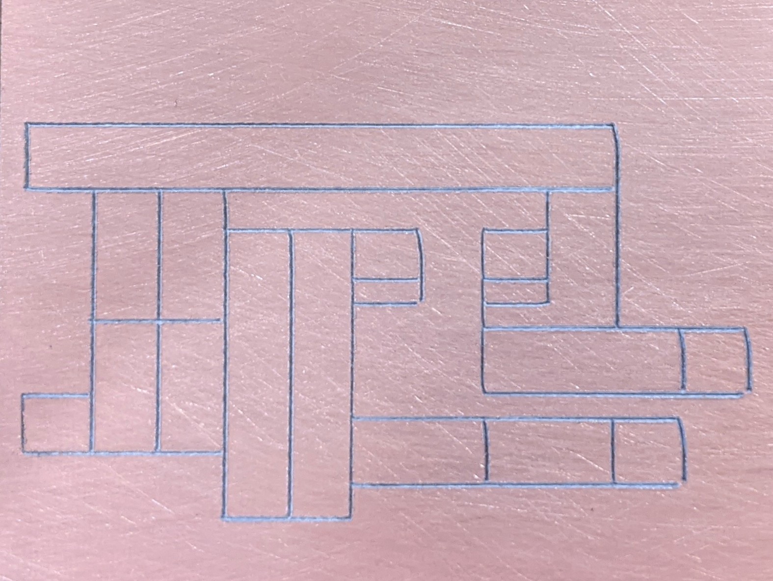
What I have done so far. I replaced all of the Carbide create polygons with straight lines - trying to maximize the length of any line segment. I also fully inserted the bit into the collet, but I had to lower the motor down in the mount a bit since there wasn’t enough travel in the Z direction for the bit to engage. Since I am not cutting polygons it is even more important that the corners connect correctly. There is enough deflection to cause some gaps - that will cause shorts to ground in the circuit.
I’ve been told by various internet experts that the Y axis anti-backlash is both “fine as is” and “the problem.” So I am a bit perplexed what to try next.
My surfacing bit arrived yesterday, but I haven’t yet had an opportunity to level the waste board.
I have purchased the 20K spindle upgrade (vs the 10K on the machine now). I was hoping to get this dialed in and perfect before adding a new variable. I wonder if the higher speed would help or hurt.
Any additional pearls of wisdom would be greatly appreciated.
Have you tried flatcam or other software designed specifically for PCB milling? I’m way out of it and don’t know what’s current, tried somewhere around 2009 and moved on, back then it was eagle and pcb-gcode. Maybe try a few simple non-pcb projects to see how the machine functions otherwise too.
The 20K spindles can be great, but it’s right at the hairy edge for startup current on 3018 power supplies. A suitable inrush current protector, or editing gcode to start slow and ramp up in a couple steps, can make them work. I have a couple, a GS-775m and the new Sainsmart version, but won’t be able to try anything for another month or so. I agree it’s best to hold off on adding variables.
These aren’t traditional PCBs where you need to clear copper around traces. These are what’s called Manhattan Style, where I am carving lines to create islands of continuity that I solder parts directly to. So all I really need to do is carve a bunch of straight lines through the copper. Any CAD software should be able to do it safely. At this point I don’t think the issue has anything to do with Carbide.
I tried the same cut on MDF and it turned out perfect. It seems the issue is the bit deflecting when it contacts the copper.
Thanks for input on the spindle upgrade, SainSmart sells it as a direct drop-in replacement for a SainSmart CNC. I found the ramp-up G-code example on their web site. Be nice if they included note in the package.
I’m getting very close to having things dialed in. I am now closer to believing this is a backlash problem, but not sure what to try to do about it. For this cut I redid the layout and replaced all the polygons with straight vectors. I also have now surfaced the waste board and reduced the DOC and plunge speed considerably. Settings for this cut - depth/pass 0.025mm, feed 125 mm/min, plunge rate: 45 mm/min, max depth 0.09 (60 degree carbide V bit).
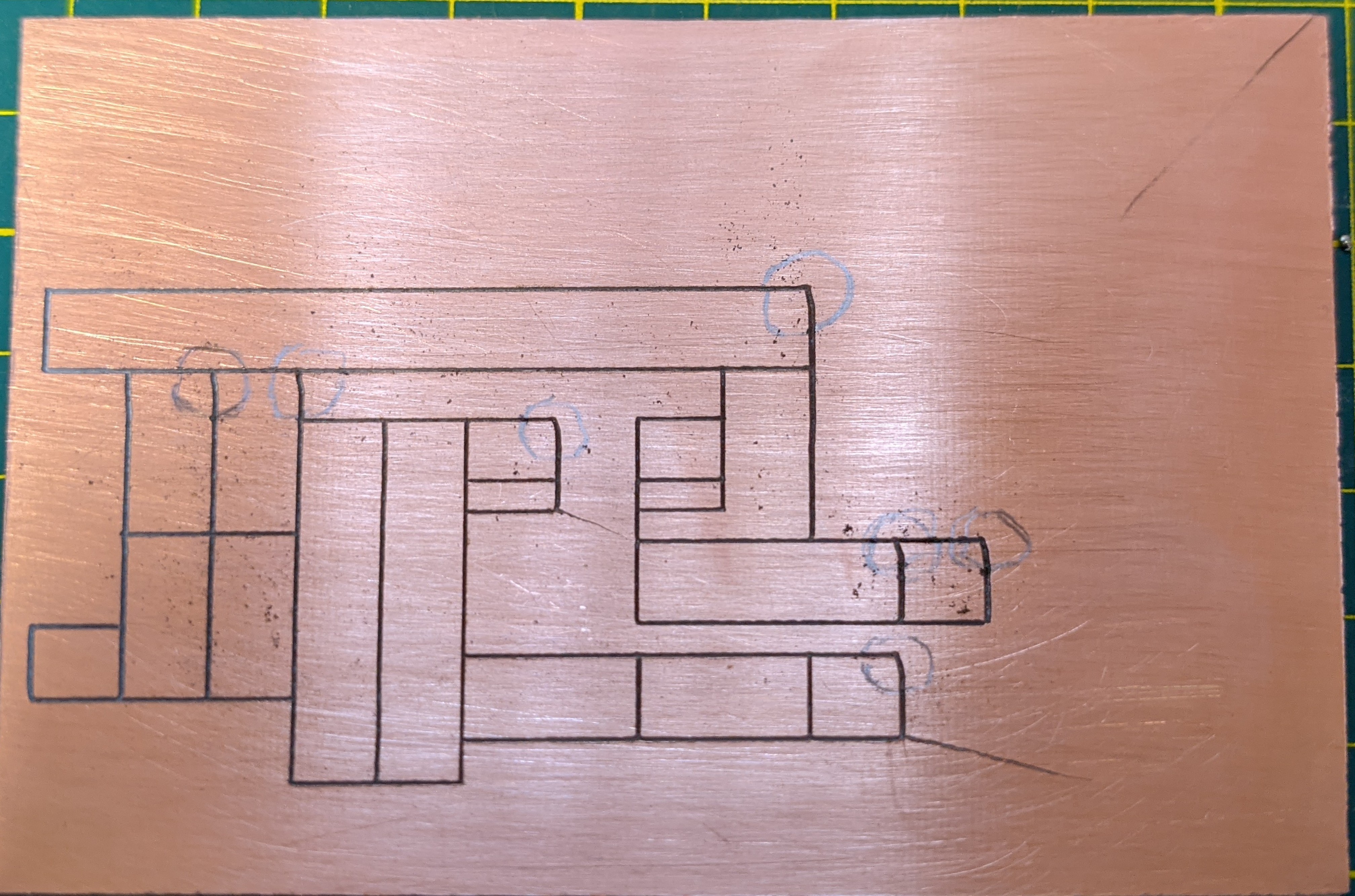
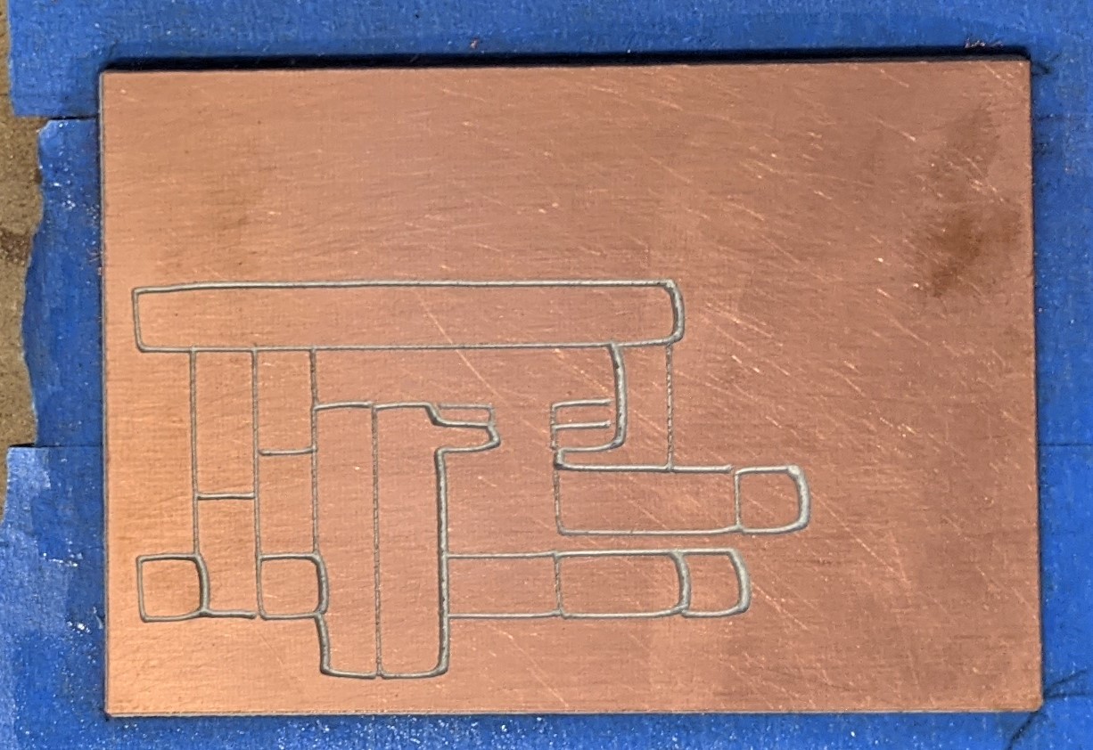
I watched whole cut this time and observed that deflection occurs only and always in cuts along the Y axis that proceed in a negative direction. In other words cuts that start nearer the top of the piece and proceed towards the bottom (circled) . Cuts that proceed in the positive direction along the Y axis do not show any deflection. These are all straight lines - the but plunges and immediately proceeds in the Y negative direction.
I’m open for any other thoughts about what to try.
If it works in MDF but not copper clad board then try slowing down, reducing the depth of cut, and/or reducing the acceleration. A quick 3018 forum search (pcb speed) found 30 to 150 mmpm and 0.1 to 0.3mm depth of cut. 3018s are built to hit a $200US price point (what I paid for my Sainsmart Pro last summer, blue tuesday or some such sale) and the Z axis can be somewhat flexy. PCB boards look like they could be tough to cut.
See how your Z (or even the whole machine) does on the wiggle test, you might find some loose screws or weak spots.
Thanks Kirk - there was a typo in my post the max depth is 0.09 - I think all of my feeds and speeds are lower than what you suggested. I’ll give the machine another once-over - everything seems tight.
And I sorry I missed an obvious problem. There was a batch of anti-backlash nuts from poor quality brass that popped up all over 3018 land a while ago, the threads would strip out. Look for brass filings/debris and see if you can see slop when wiggling the nut. You might be in the period between grinding and failing with increasing slop in the fixed nut. It’s a warranty issue, I’ll comment in the other forum when I dig up your post
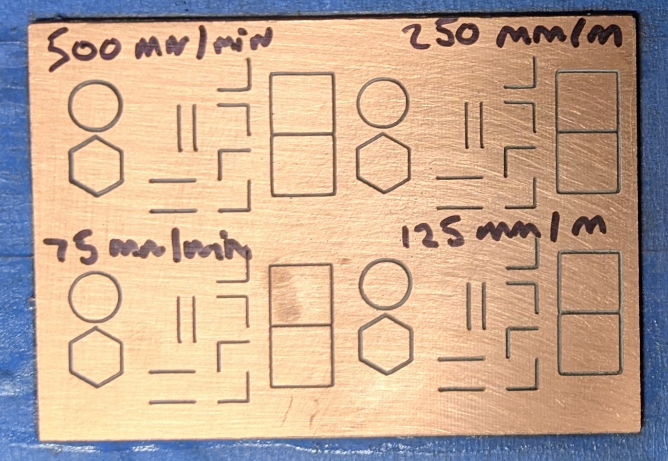
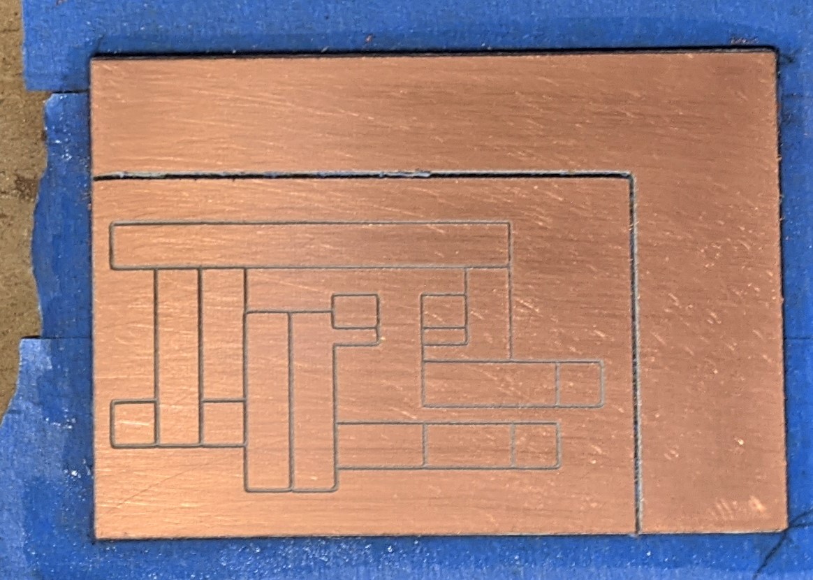
Thank you to all who have offered help and advice. After considerable testing, re-seating the anti-backlash nuts and numerous other things, I finally asked SainSmart for a warranty replacement of the XZ assembly, screw rod and anti-backlash nut. After installing the replacement parts I made these test carves - trying different feeds and speeds. The cut quality is greatly improved - I would say 99% correct - circles look like circles instead of squashed eggs. The bit no longer deflects when carving from the +Y to the -Y direction. Interestingly there is a small deflection in cuts that proceed from -Y to +Y which is a bit more pronounced and higher feed rates. For completeness - depth per pass is 0.083mm, depth of cut is 0.25mm, plunge rate is 75mm/min. I varied the feed rate from 500 mm/min down to 75mm/min. I’d sure like to still get it 100% correct - but it is good enough for my purposes - and I suspect the effect will disappear entirely in wood carvings or anything with larger features.
I appreciate everyone’s willingness to pitch in with suggestions and welcome any more thoughts.
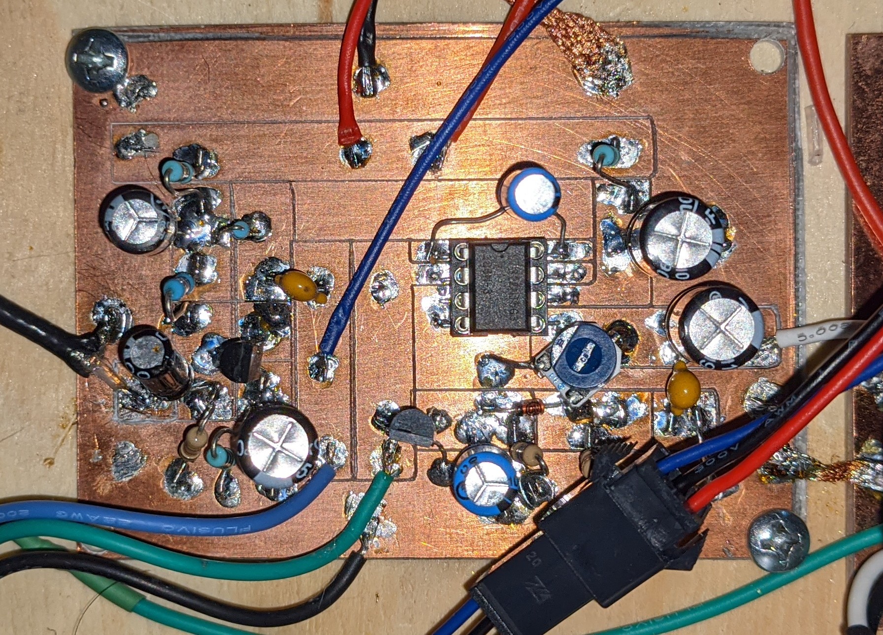
And if you have wondered what this is for… this is an audio amplifier with automatic gain control for a homebrew ham radio (built on an early version of the carve with defects, I had to manually adjust some of the cuts with an Xacto knife.)
Great to hear you sorted it all out! Your results are much better (though still subpar compared to a … cough… nomad… cough )
I’m curious about your before and after images… the blue tape and glue is absolutely identical for both shots… did you photoshop/paste the new board over the picture of the old board for better A-B comparison ? If not, you have a very specific way of tearing and gluing
 which aren’t particularly cheap but work very well. I have a very old Protomat90 (1990’s vintage) that I keep running and it does a fantastic job.
 )
)