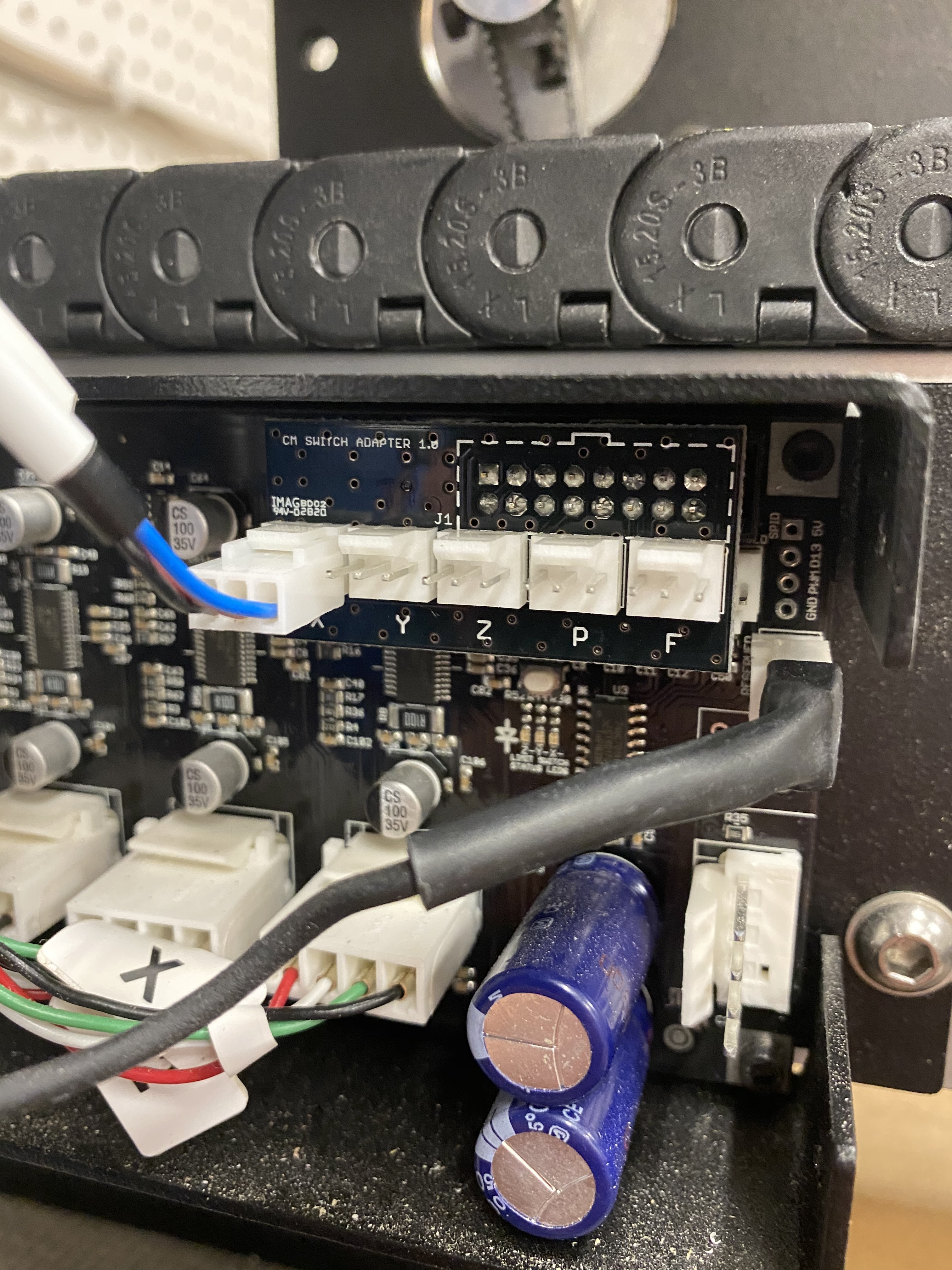
The Z Plus upgrade (and HDZ 4.0) come with inductive homing switches that plug into an included PCB Riser Board that plugs into the conroller. But the Riser Board blocks the existing Feed Hold pins:
Assuming the wiring on the one you have plugged in is standard proximity switch coloring…
Black is input, blue is ground.
Left and Right
Middle is +5V (not necessary on a switch)
I agree, but I think that’s how it is. I’m just basing this off the wire color on your X prox switch. Got a multimeter?
The wire color scheme is already confusing on those proximity switches. I can’t get “black is ground” out of my head. I’d be surprised if they mixed that up even more.
Appreciate your ideas. I have a multimeter but the machine is still down for the upgrade. I have an email into Support for an official answer. Anybody with a Feed Hold button will be affected if they upgrade.
@neilferreri is correct. I heard from Carbide3d support and got this response:
“There are a set of pins on the same header as the homing switches labeled feed hold, on the Z plus riser “F”. This is similar to hitting the pause button on the software when the connection is closed between these pins. Be careful of the B pin it has voltage and will short if connected to the other pins.”
Nope, the BitSetter is a probe too, so they both go to the probe input, hence the need for the splitter board. I’m unclear as to what connector is currently shipping with the BitSetter though, and how one would connect the splitter board to the “P” input of the riser board, so in case of doubt a mail to support@carbide3d.com will clear things up.
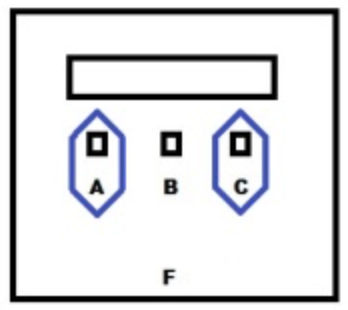
On 2.4d/e boards there is a separate connector marked ‘reserved’ that is used for the probe as pictured below.
Both probes will physically fit both this location as well as the riser location.
Thus, I was thinking the splitter board would not be needed if you could plug one into the reserved port as per the image and the other on the riser board…
I think it would work, however, I’d rather not do anything to break stuff in order to test…
Got it. It should work (the probe input just detects shorting between a signal pin and ground pin, so one can have multiple devices in parallel, but you should definitely get confirmation from support…don’t take my word for it.
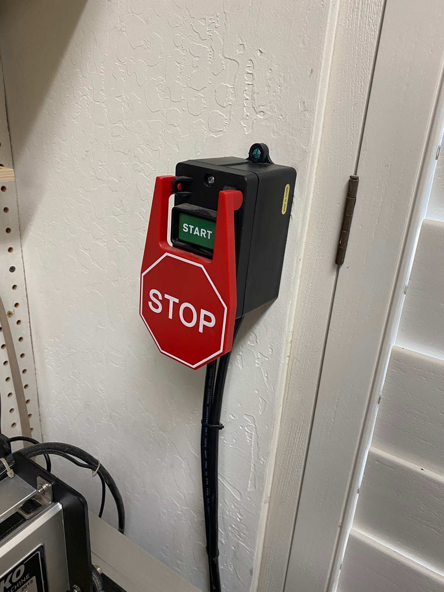
Thought I’d share my Feed Hold button implementation, successfully wired to the outer pins of the FH connector on the new PCB riser board. It’s close by so I can find it instantly when needed without hunting for the “Pause” button in Carbide Motion on my laptop, which is farther away from the machine.
It has been a long time since I wired a molex connector. I seem to remember it took special tools. Can you get the connector neilferreri referenced pre-wired ?
I visited a friend who has been repairing computers as a hobby / business for years. He has a cupboard full of miscellaneous components that may never see the light of day let alone usage. When I asked if he might have a fan header cable he cautiously opened the cupboard door and felt around in the dark interior and pulled out a … CPU fan / heatsink for a 266 MHZ CPU. The cable and connector was just what I need.
The cost was I had to dispose of the unused fan and heatsink.