I’d like to take this picture of my Grandson and make a 3D carving of it.

3 Likes
For Carbide 3D’s eco-system there are a couple of options for making a project from a photo:
- halftone — this would be a direct 2D representation:
- lithopane — this uses the fact that a representational photo can be easily mapped to light/dark, then illuminated to make a lighted view of it:
(not sure if MeshCAM still supports that — it should be possible to convert the pixel image to a greyscale, then smooth it a bit and adjust the contrast, then import into Carbide Create Pro — probably there are specialty programs/sites for that)
-
auto-tracing — this can work on some photos which have clear well-delineated areas, but isn’t really an option for most
-
re-drawing — import the pixel image as a background, then re-draw to make a 2D representation
Once one leaves Carbide Create’s featureset, then other tools may come into play
- using a LLM to create a 2D image or 3D model — some folks have had success with this approach:
- manually sculpting the design using software such as Blender or Z Sculpt — there are some folks who are _very_talented at using such software here, and it may be that someone will be better able to advise or assist on this aspect, or maybe contact you via a PM and do it for you.
@thehootens Not sure this Link will work, but you can try this STL for import.
I was wondering what I was going to do this morning …
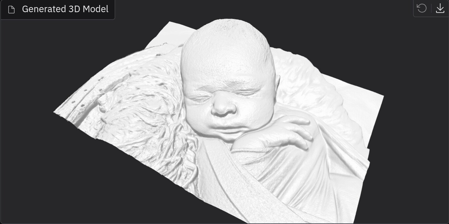
Here is my attempt. I used Fusion to convert the image to STL.
Use a gray scale version of the image to get a feel for how a conversion may work.
These programs use contract ( black to white ) to determine heights.

Here is a render of the conversion.

I put a STL file on Google drive.
Please let me know when you are done with the link or have issues getting access.
1 Like
I also did one before I read the entire thread. Let me know if you want it… ![]()
I can’t seem to get the design open. It looks awsome.
The files in question are STLs, which is a standard 3D file format:

In order to use them you will need a 3D CAM program such as Carbide Create Pro:
Once you have such a program, it should work to follow the documentation:
https://carbide3d.com/hub/courses/create-pro/3d-tool-import-stl/
and then import the file:


adjusting the settings to arrive at:
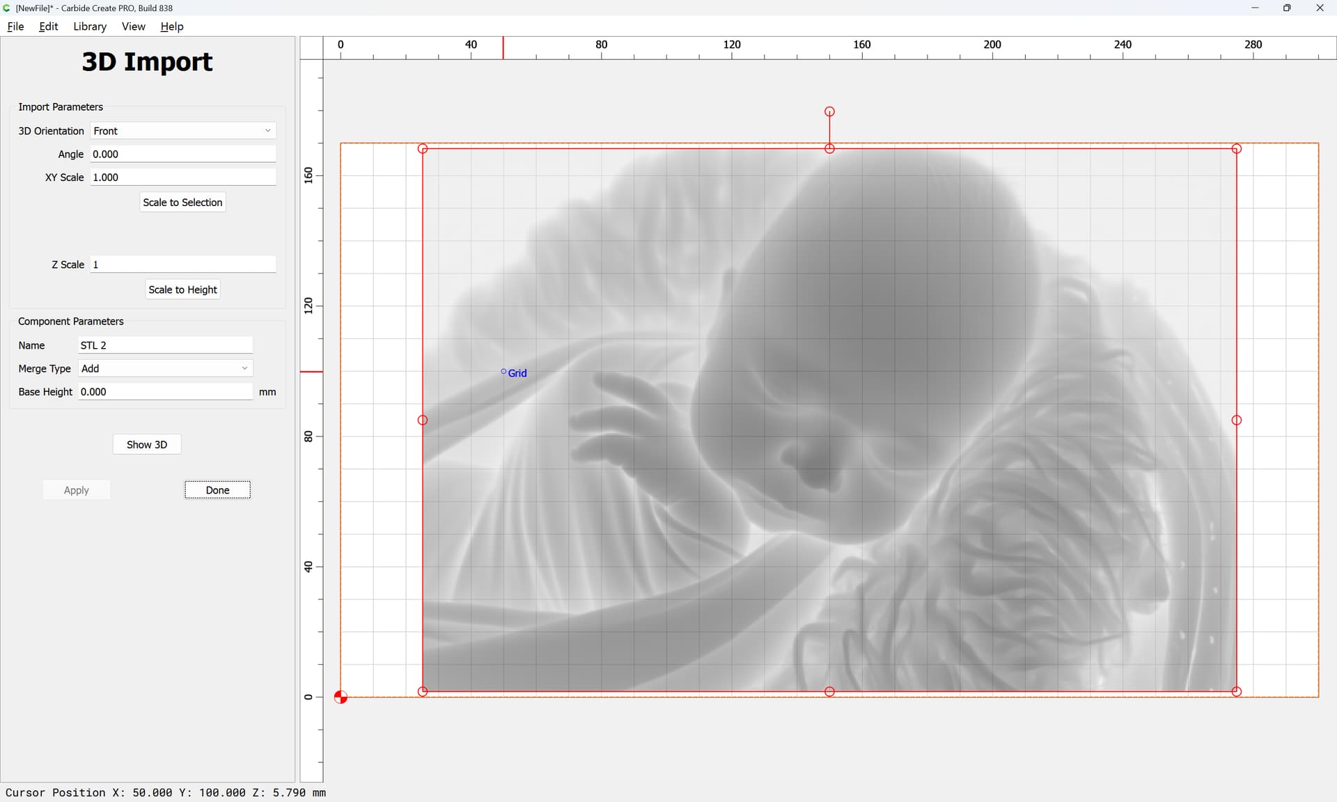
which previews as:

and if one sets up toolpaths:

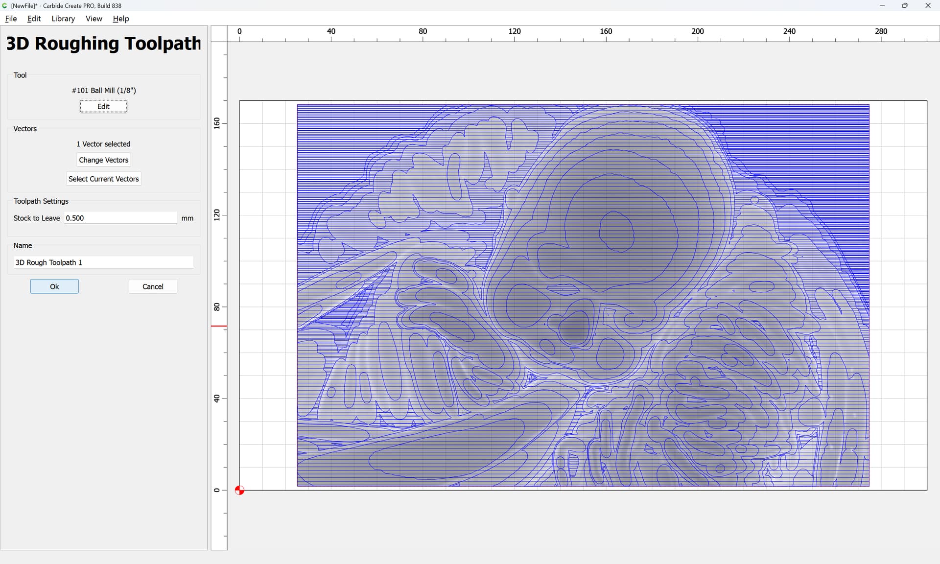

adjusting the Stepover:


Previews as:

(too large to attach)
1 Like
I think I got it I’ll Try it out
It seemed like a proud Papa, so I had to jump in.
2 Likes
I am glad you did. He isn’t going to get much sleep in the near future. ![]()
1 Like
Worth every minute . 20 chard
I made a free web app a while ago that uses monocular depth estimation (instead of just grayscale height mapping) to give some convexity to these sorts of reliefs. It’s hosted here if anyone finds this thread and is interested.
8 Likes

I have a “problem” image that I am in the midst of trying to carve.
This thread could not have been timed better.
Please explain the settings a bit. I will be testing away, but instructions would help.
THANK YOU !
Here is a first pass with your default settings.

This is MUCH better than any previous attempt ( including a lot of image editing ).
This uses the initial depth map from mde, and then adds or subtracts from it using weighted luminance values from the image to give texture.
- “Brightness texture strength” controls how amplified the luminance values are and how exaggerated the texture is
- “Depth map smoothing” is a kernel size for a gaussian filter applied to the depth map
- “Texture smoothing” is a kernel size for a gaussian filter applied to the luminance values
- “X length” controls the base horizontal dimension of the image
- “Min/max Z height” control the lowest and highest positions of features in the STL file. If you want the depth to be more exaggerated, increase the max z height.
- “PCA planar correction” fits a plane to the generated 3D points and redefines the z axis as normal to that plane.
- “Close body” adds walls and a floor to make the STL a closed body, but it’s implemented kinda jankily at the moment
Looking at your example, you probably want to increase the max z height for more dimension, and then add some mild smoothing to the base depth map to reduce the spikey rigging.
2 Likes
Thanks for the information !!!
I will try an image without the background and with a bit more contrast.
So I stayed with the default settings.
The image is 3200 x 2149. Your site scaled it down. What is your max image size ?
I am not getting a preview STL.
The new result are impressive. Any other suggestions ?
I appreciate the efforts !
Edit:
I get a STL preview after downloading the STL file.
Edit 2:
This is far and beyond anything I have made with this image with little image preperation.
Wow !
1 Like
I’m glad you found it useful! I don’t remember the internal resolution off the top of my head. I wanted the transformer to run smoothly on the cheap tiers of hf spaces. These sites are just git repos, so it’s possible to copy the code and run it locally with whatever resolution adjustments you want.
1 Like
Is this development complete as far as you are concerned ?
If so, I will try to run it locally. If I can figure out how to do that …
Again, awesome work !
1 Like
I’ve been playing around with it as well and I like it a lot!
I’m definitely no pro when it comes to this stuff but … The image I’ve tried to convert to STL in the past hasn’t always worked out but in 5 minutes I had an STL that I can work with using your tool. The image doesnt show all the detail but when I rotate and zoom in CC simulation its looking pretty good. I’ll play with the setting some more to see if I can fine tune it more.
Well done!!!

1 Like
I tried a 32 bit PNG image ( with transparent back ground ) and the app created a mesh for that area. All good, just a heads up.