I have made some edits to a svg on carbide create. Such as a curved and straight lines. When I go to tool path they are not cut? Any takers? LOL
Hi @Engine1,
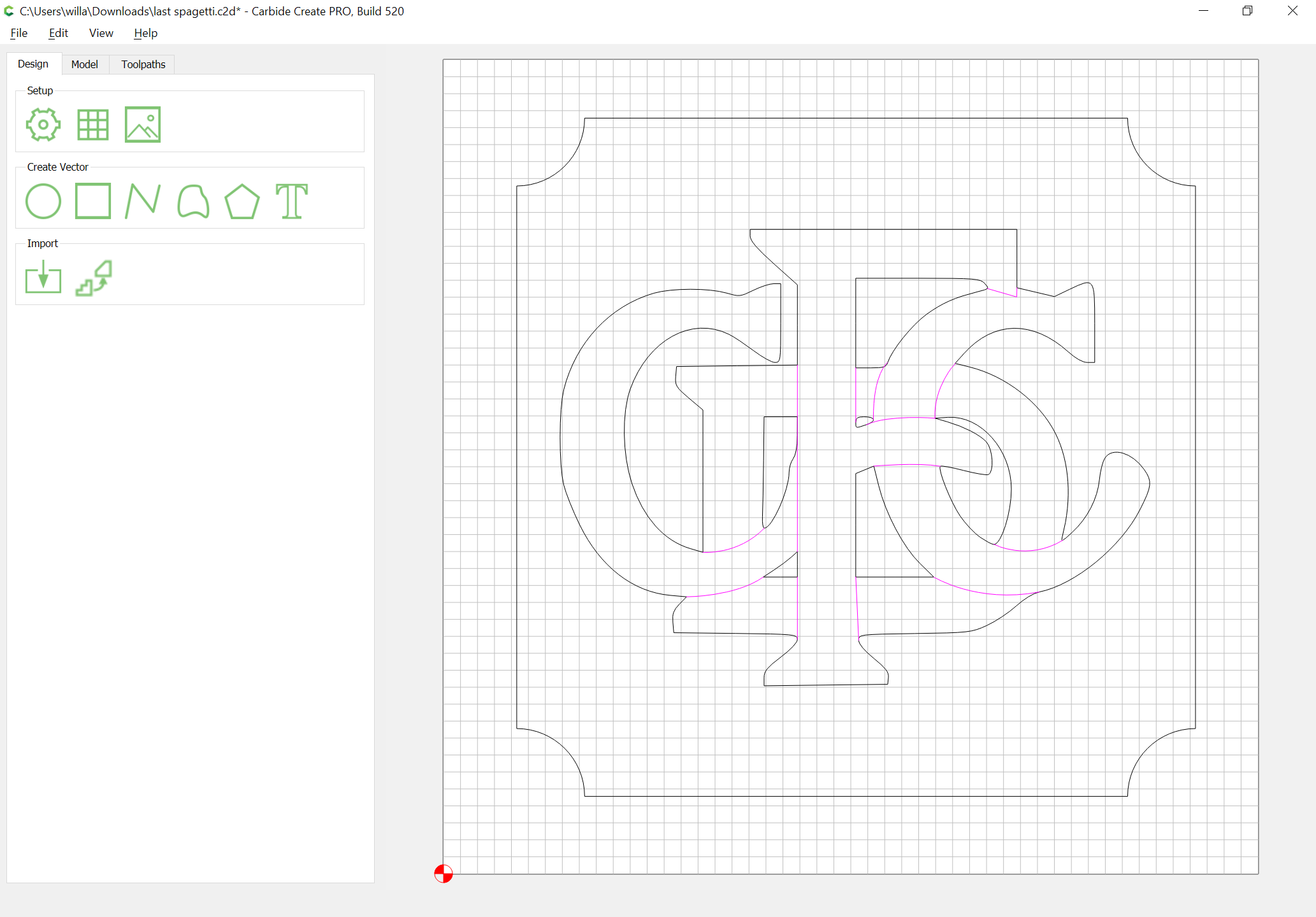
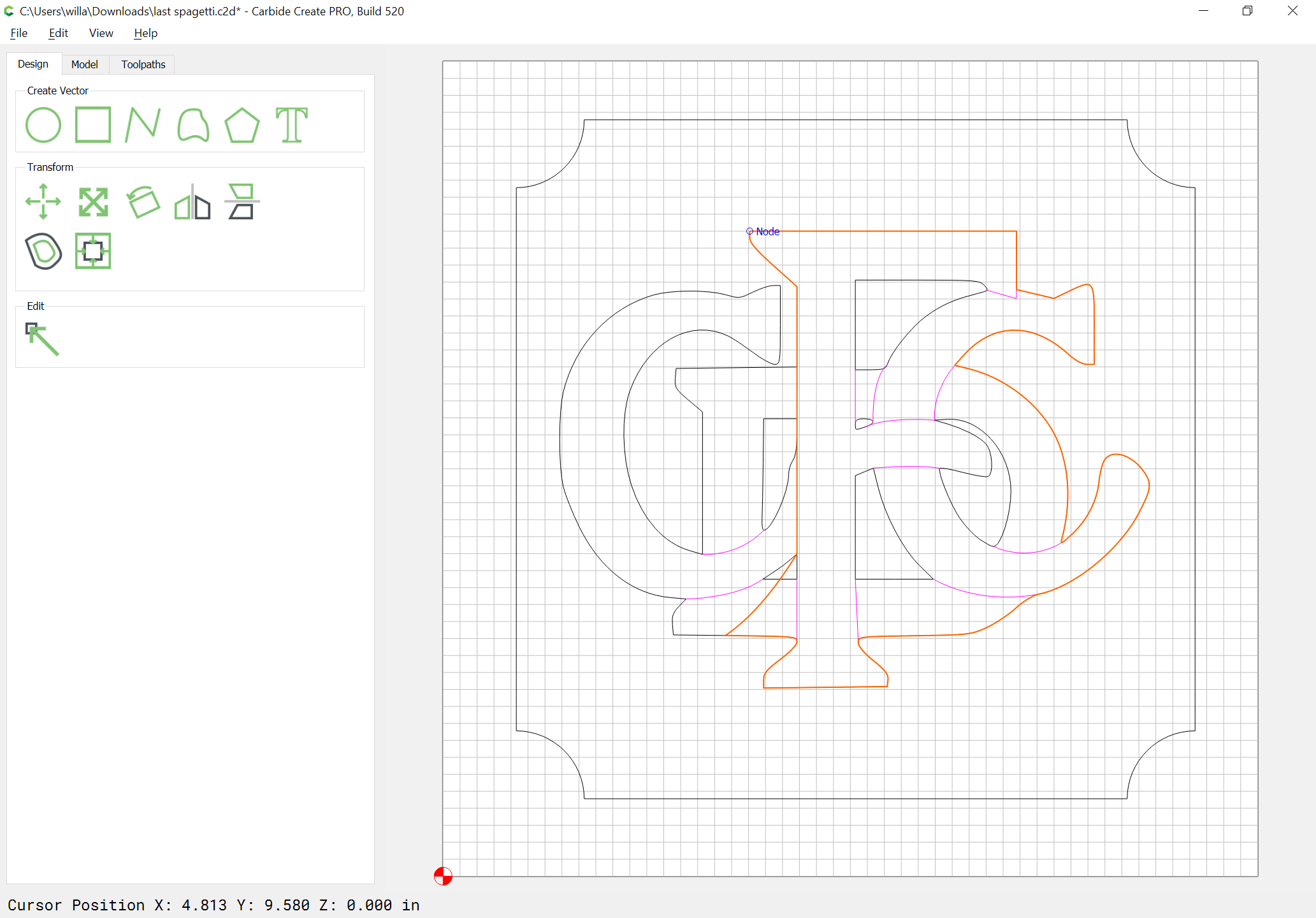
pink lines indicate open vectors, while the toolpaths require closed vectors to work.
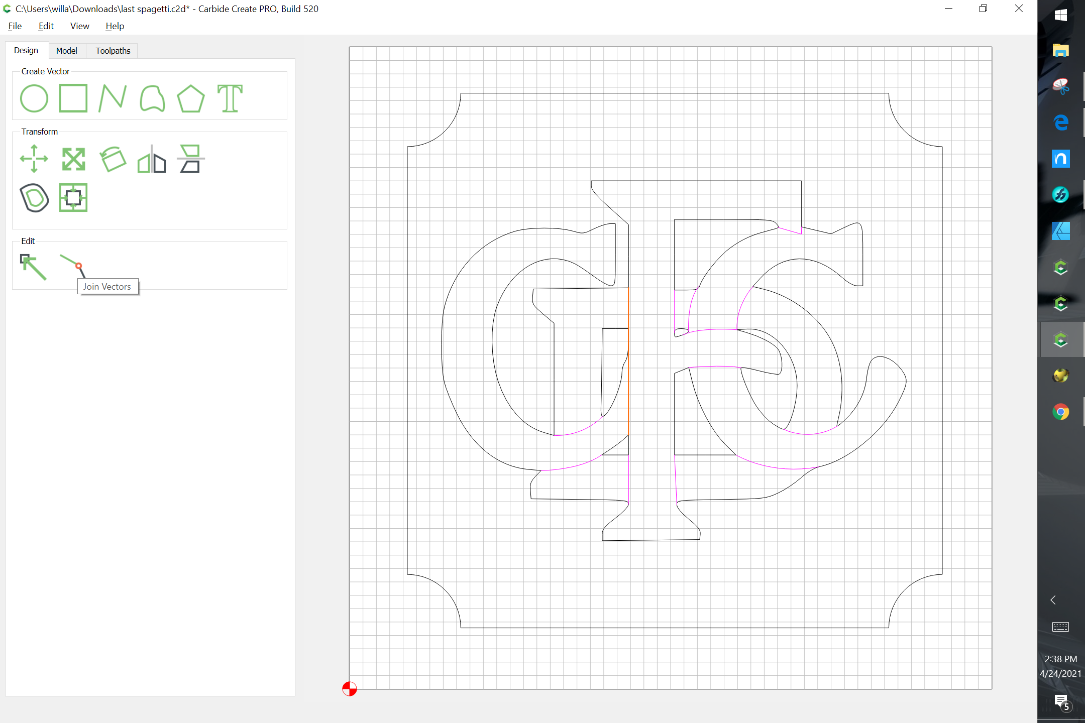
There is a “join vector” feature in the menu to fix that manually.
Upload your c2d file and we’ll have a look ?
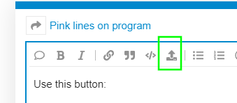
Where do I upload the file too?
Use this button:
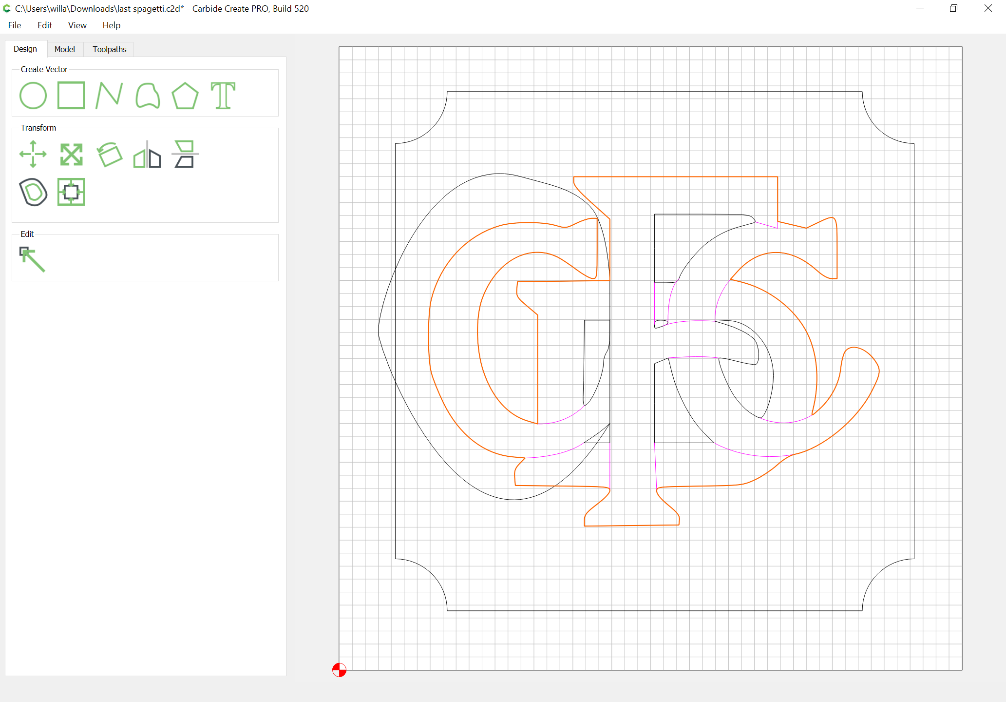
last spagetti.c2d (90.9 KB)
Yeah so the letters are a mix of various vectors, some closed some not,
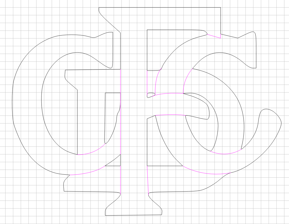
And it would take some effort to fix it all (unless you have @WillAdams’ magic CC power), so I’d rather ask first: how did you intend to create the toolpaths for this? (assuming the open vectors problem is sorted out). The overlapping letters and tight corners may be tricky to get right, even with V-carving
Post the file and a description of what you wish to do and we’ll do our best to assist.
I am partially color blind and cannot tell the difference between Magenta (open vectors) and the red/orange of a selected item. I see the same shade of red for almost all reddish colors. I have been caught by open vectors because I thought they were just selected. There is the close vector tool. If it is available it will be right next to the edit node tool
1 Like
I do have that tool but it doesn’t seem to do anything.
You have to find out which of the images are open vectors. Select that object and join vectors. If you select them all that wont work. Select each object and try until you get it right. The closed vectors wont be affected by the close vector tool.
Unfortunately the situation is slightly more complicated here (see the file Joel uploaded), it won’t be as simple as using the join vectors, and some manual node editing (probably beyond CC’s abilities) is in order. OR, Will will find a trick. But the core question is if it is worth fixing, depending on what is the intent afterwards for how to cut this logo.
Which I believe is defined as unending patience and perseverance!
1 Like
last spagetti.c2d (90.9 KB)
I am trying to make purple or pink lines orange so they will cut.
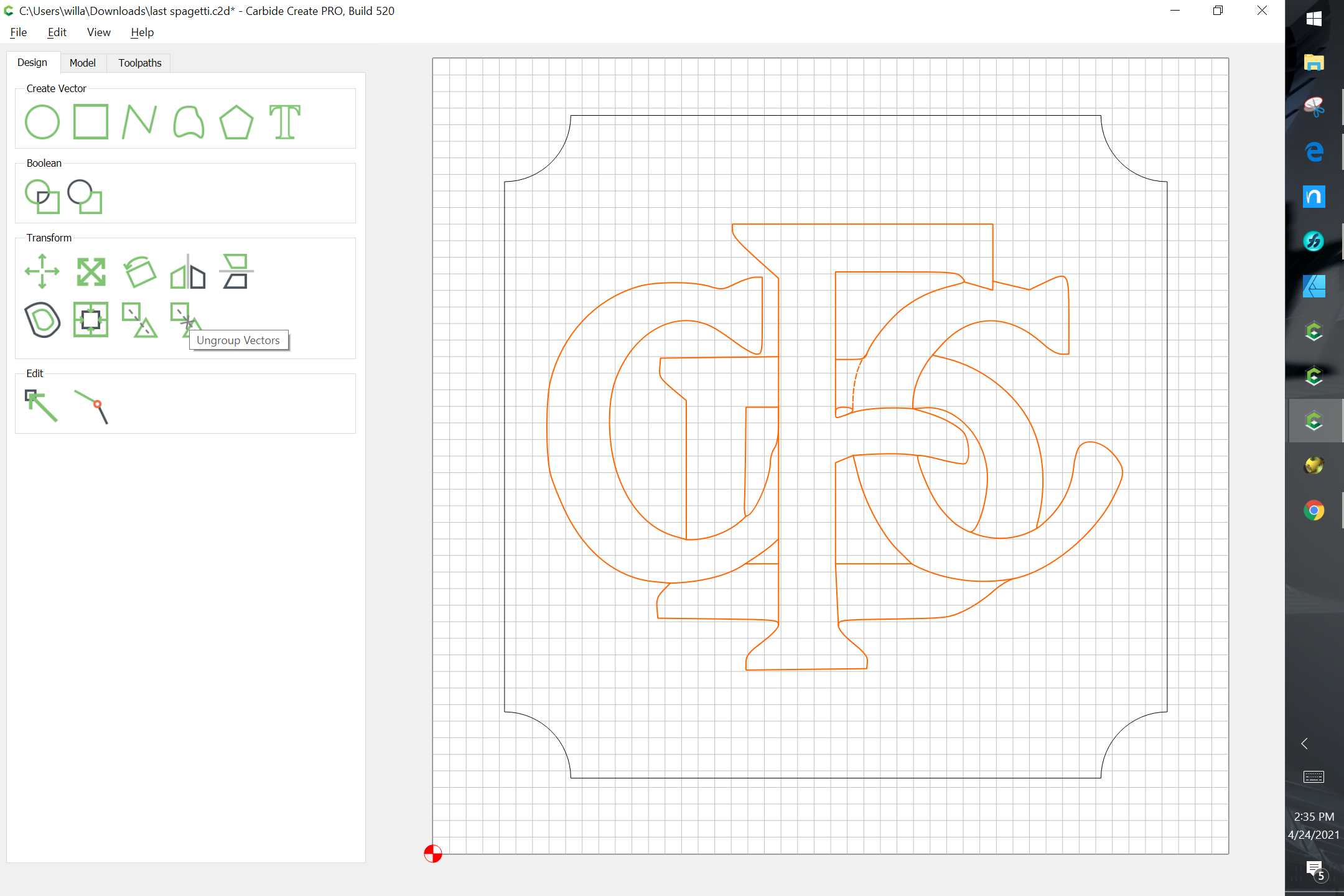
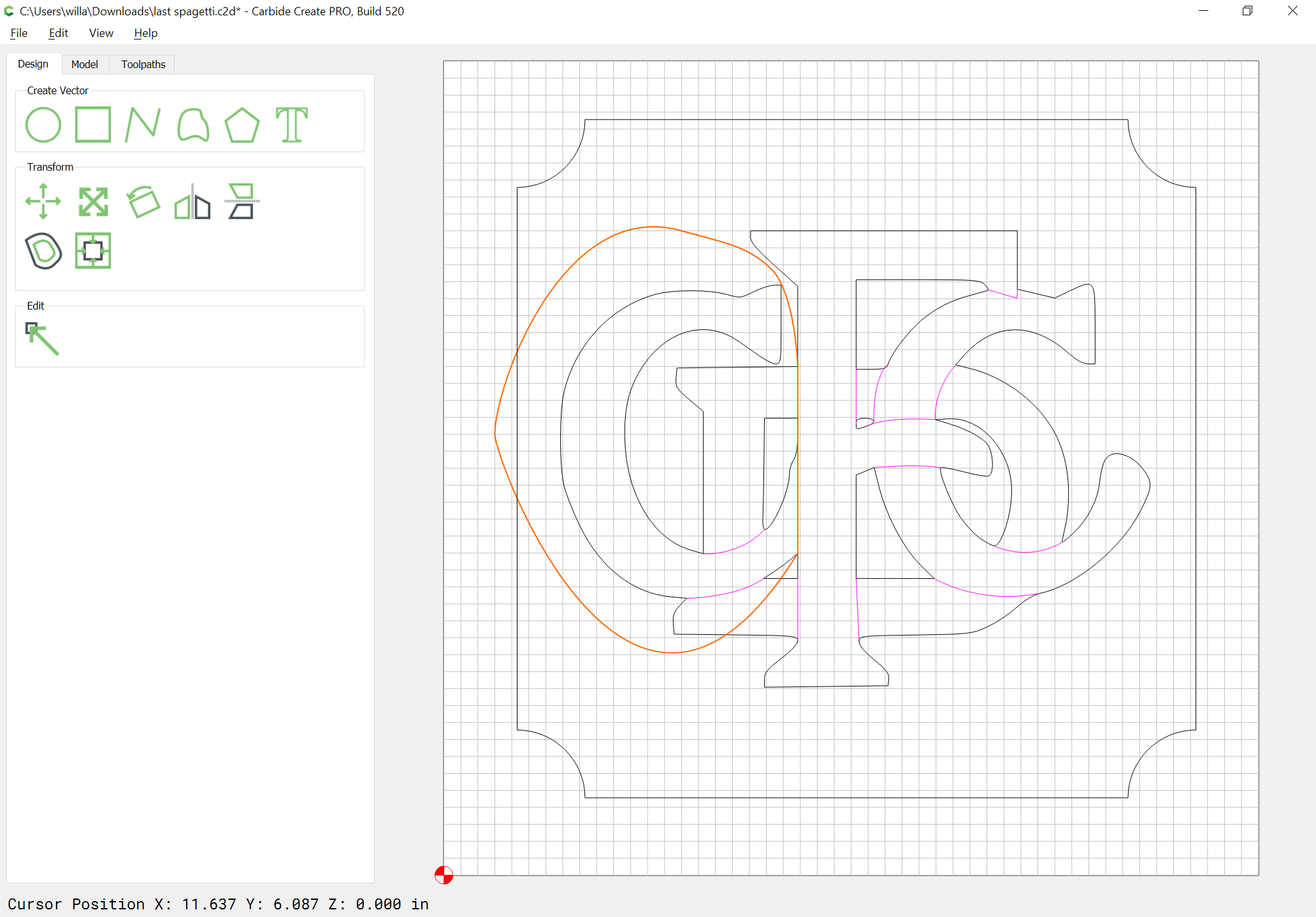
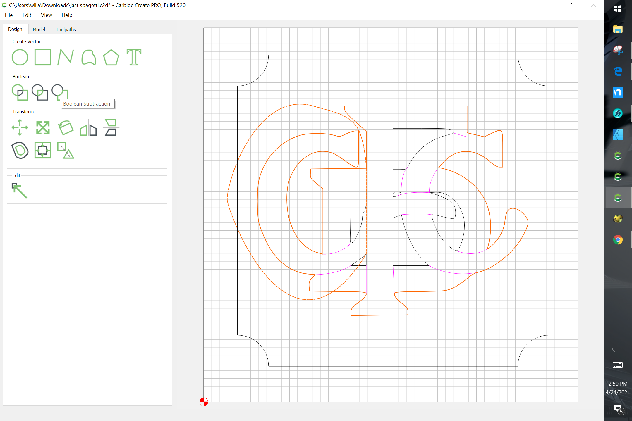
Open the file, select things and ungroup:

repeat until there are no more groups:

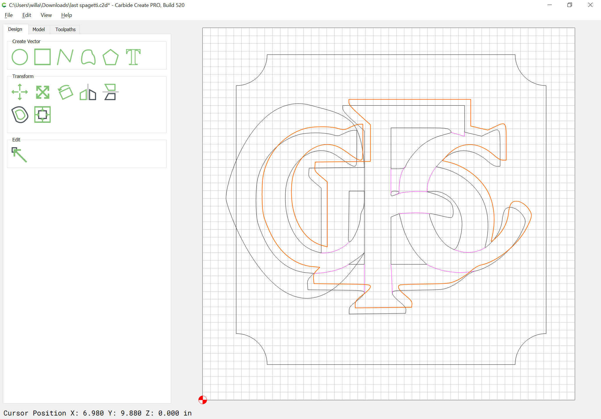
Then, select each open path, close it, and modify it so that it can be used to interact w/ a duplicate of the closed geometry.
1 Like
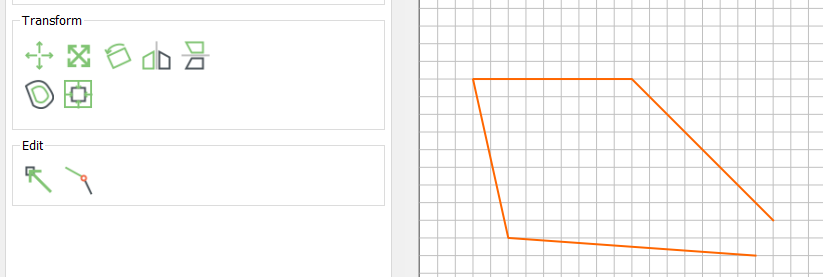
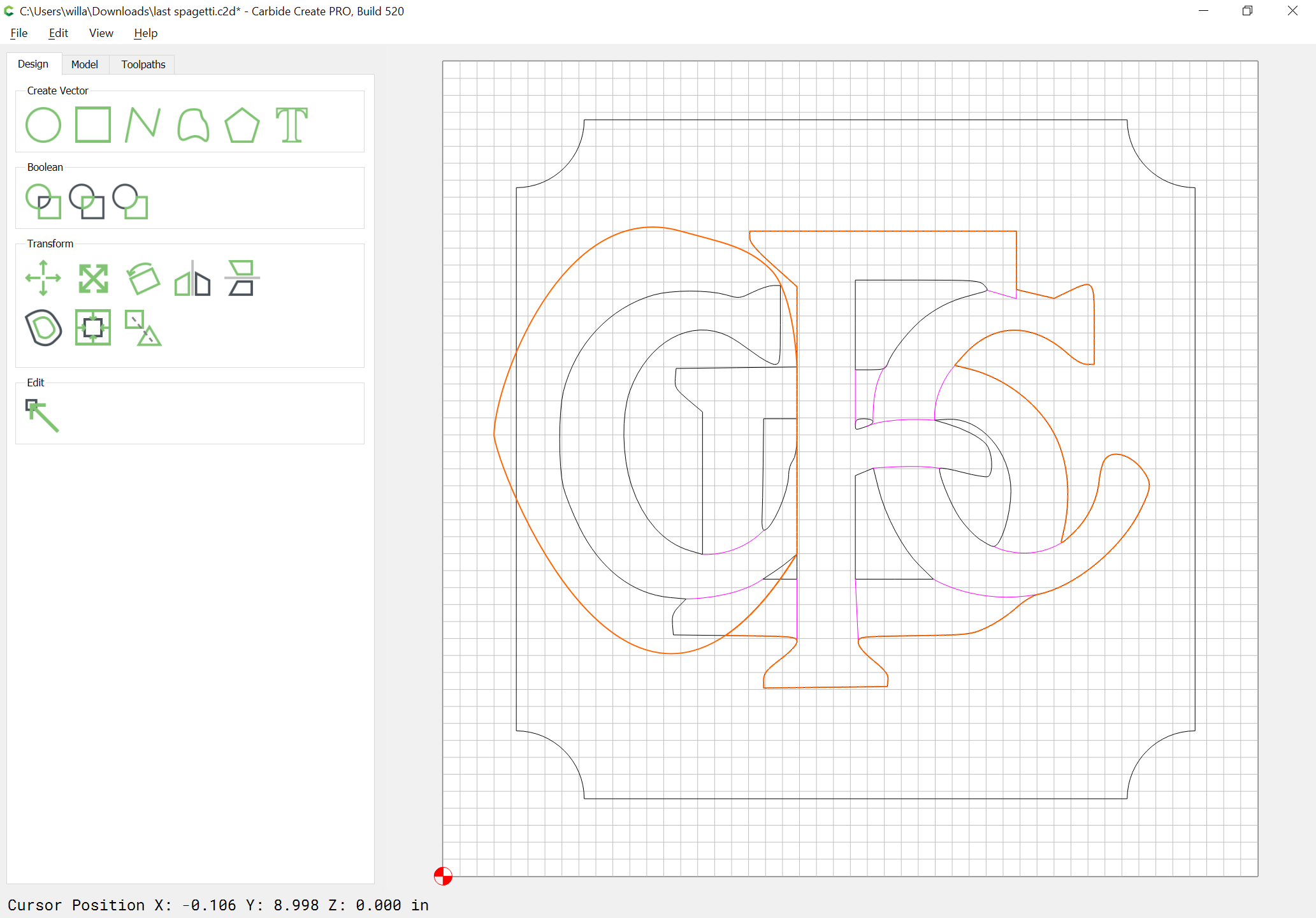
Go into Node Edit mode:

add nodes as necessary:
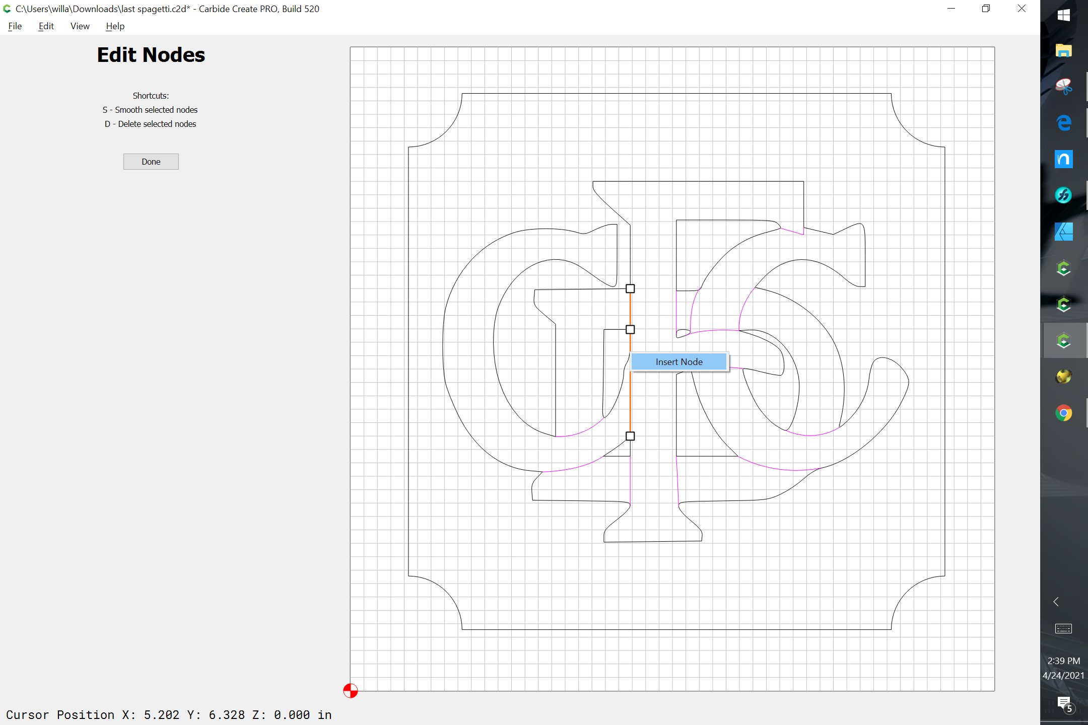
and drag them out to encompass the closed geometry:
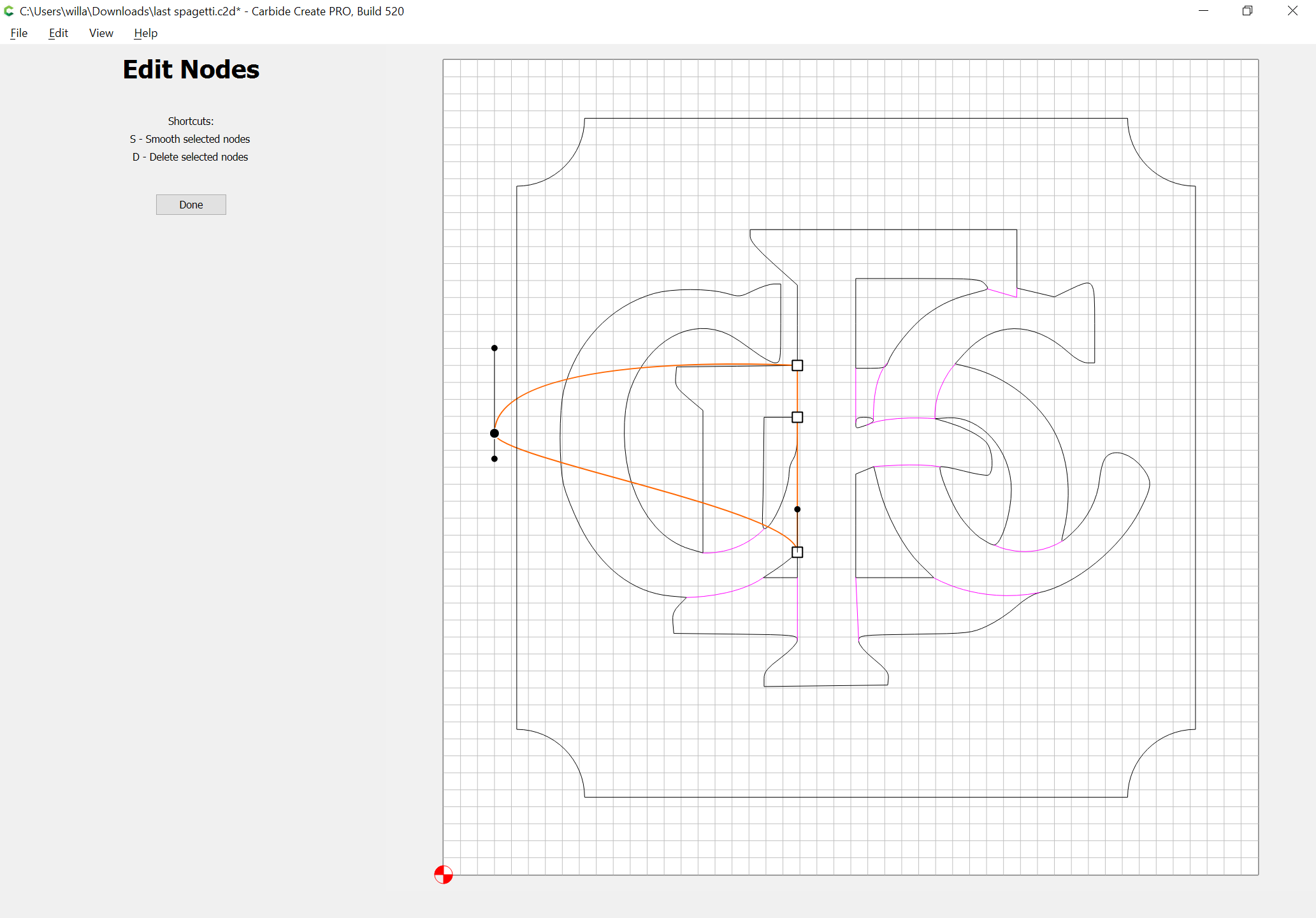
repeat until the geometry is ready for a Boolean operation:
Done
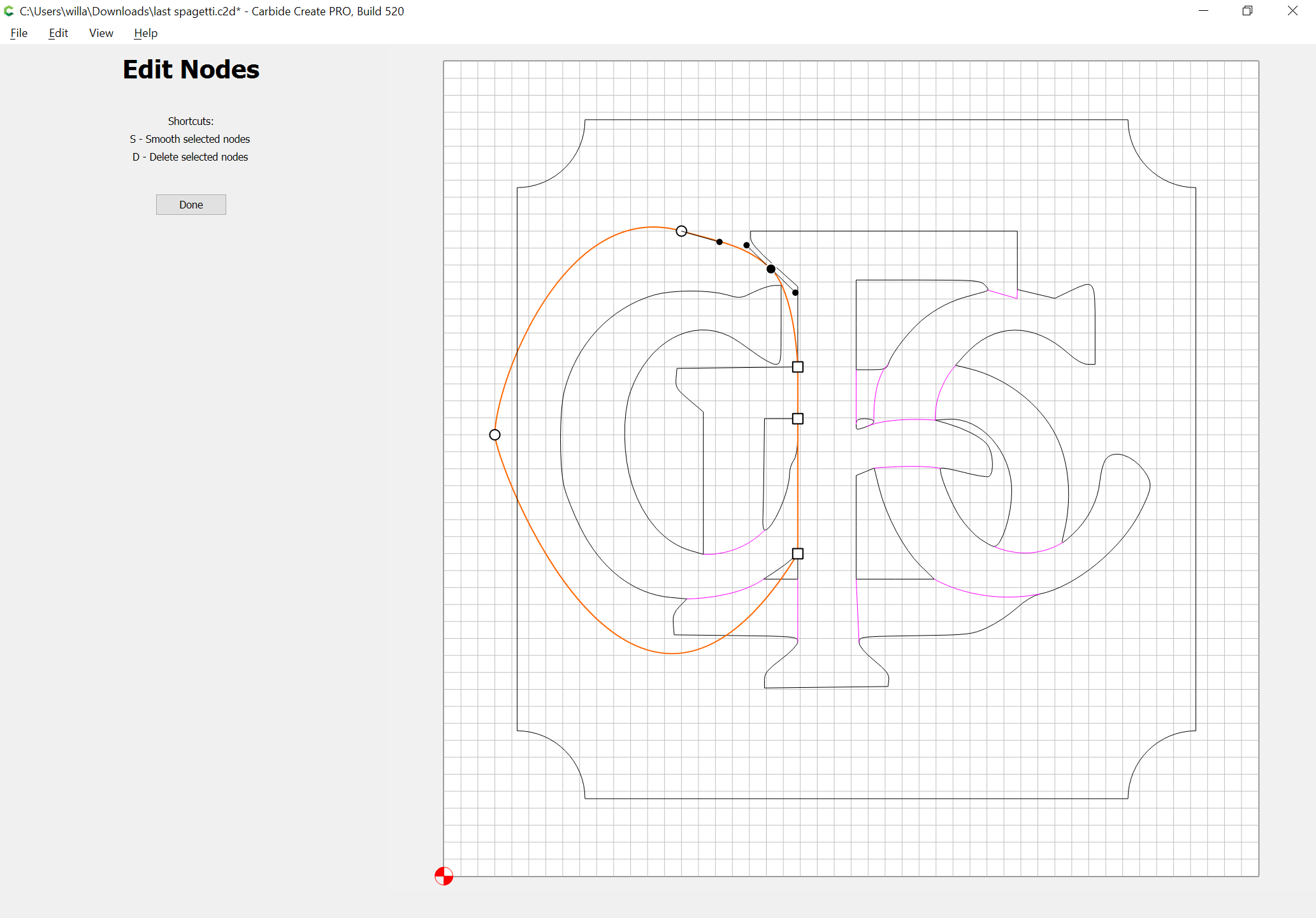
Select the main geometry and copy/duplicate it:
and drag it back into registration with the original:
shift-click on the modified geometry to make it the key object (indicated by a dashed highlight):
and Boolean Subtract:
Delete the unneeded geometry:
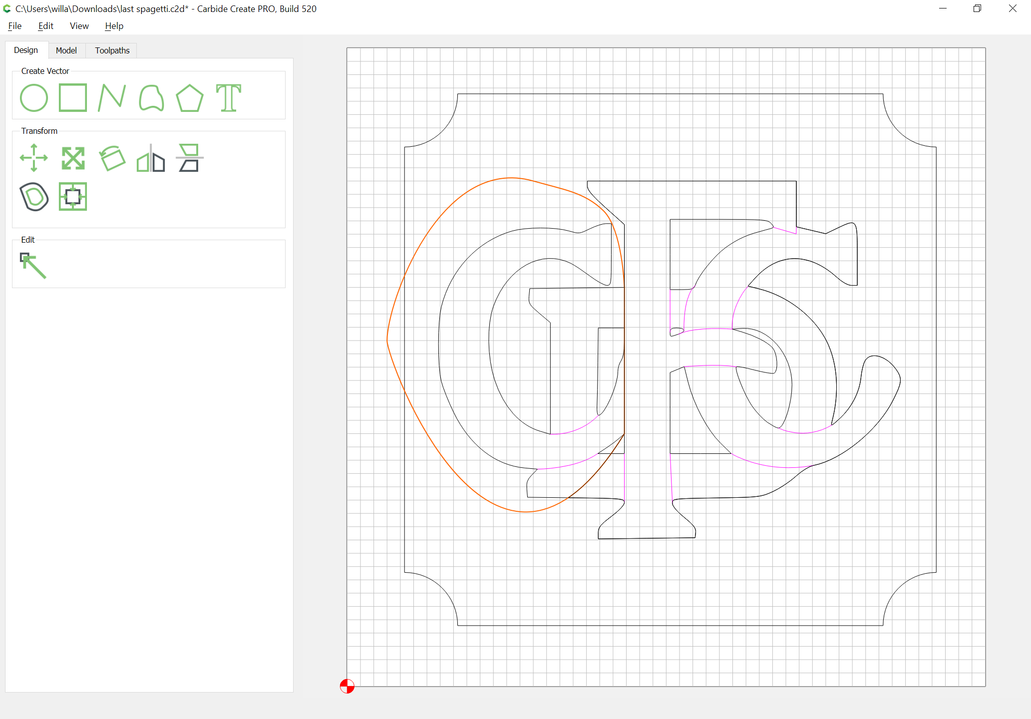
and repeat this for each section which has open geometry.
No pressure on Will. Majic again.
1 Like

I truly appreciate the time you spent on that answer, but I am more lost that before… Ill just have to pay someone. very disappointing.
Please wait a bit, I’ll have a finished file presently.
The guidelines are:
- for any region which you wish to have cut to a particular level, or using a particular style of toolpath, you’ll need closed geometry
- where you want a stacked effect you’ll need multiple geometries enclosing all but the lowest region
- open geometry is best suited for special effect and cannot be used for dividing two regions into different heights
Above all, please note that we have a standing offer — if you get stuck on a file or project send in to us at support@carbide3d.com and we’ll do our best to work through it with you.
1 Like