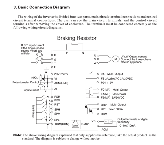
With the 3 wire hooked up. It had 2 hots and a ground, which run directly from the outlet to the panel. The plug is hooked up the same way. I had to get a bigger plug with 4 terminals since it is 4 wire and on the outlet, theres 2 hots a neutral and a ground. The plug and what I assume the “L” shape on the plug you referenced is indeed the ground.
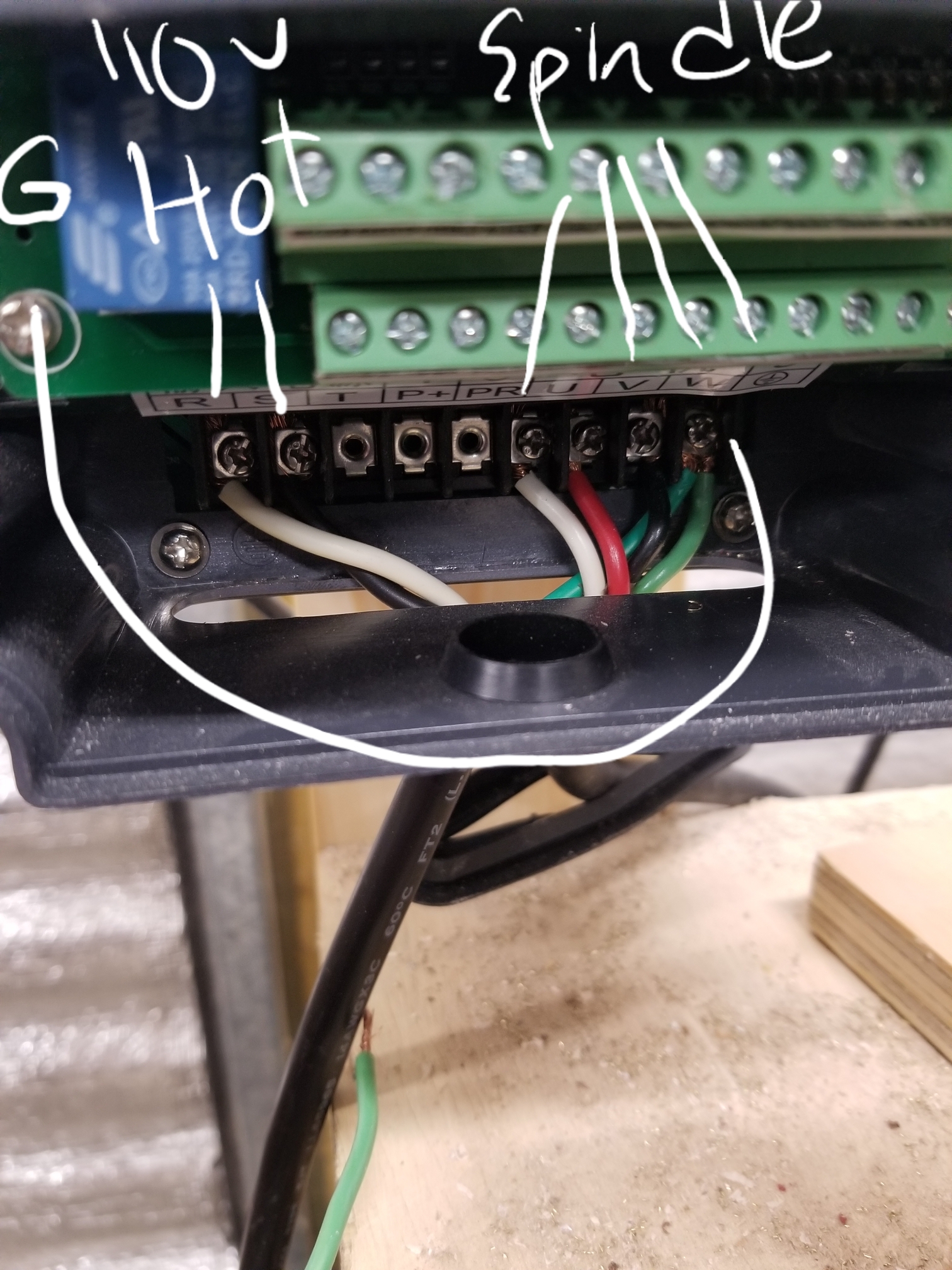
Did you disconnect the white wire from terminal T?
If I were to do that, should I just cap it or go back to the 3 prong plug?
Going back to the 3 prong plug would be the right thing to do. Just make sure the green wire is connected to it’s L shaped contact.
Yikes, yes, do not connect any earth to the R, S or T three phase input terminals on that input rectifier.
Your VFD is using the Earth as one of the phases and a current source / sink. If your TV is changing channels on it’s own that’ll be why ![]()
Those terminals should have the 240V hot / hot on any two pins and nothing on the third.
EDIT - You should absolutely earth the Earth pin on the VFD and ensure the spindle has solid earth too - your breakers, RCD etc. can’t help you when you’re on the other side of the VFD
If you have real three phase power (Germany) then you can connect all three R, S, T but not for normal single phase users.
Should I run a ground straight from the panel to the vfd?
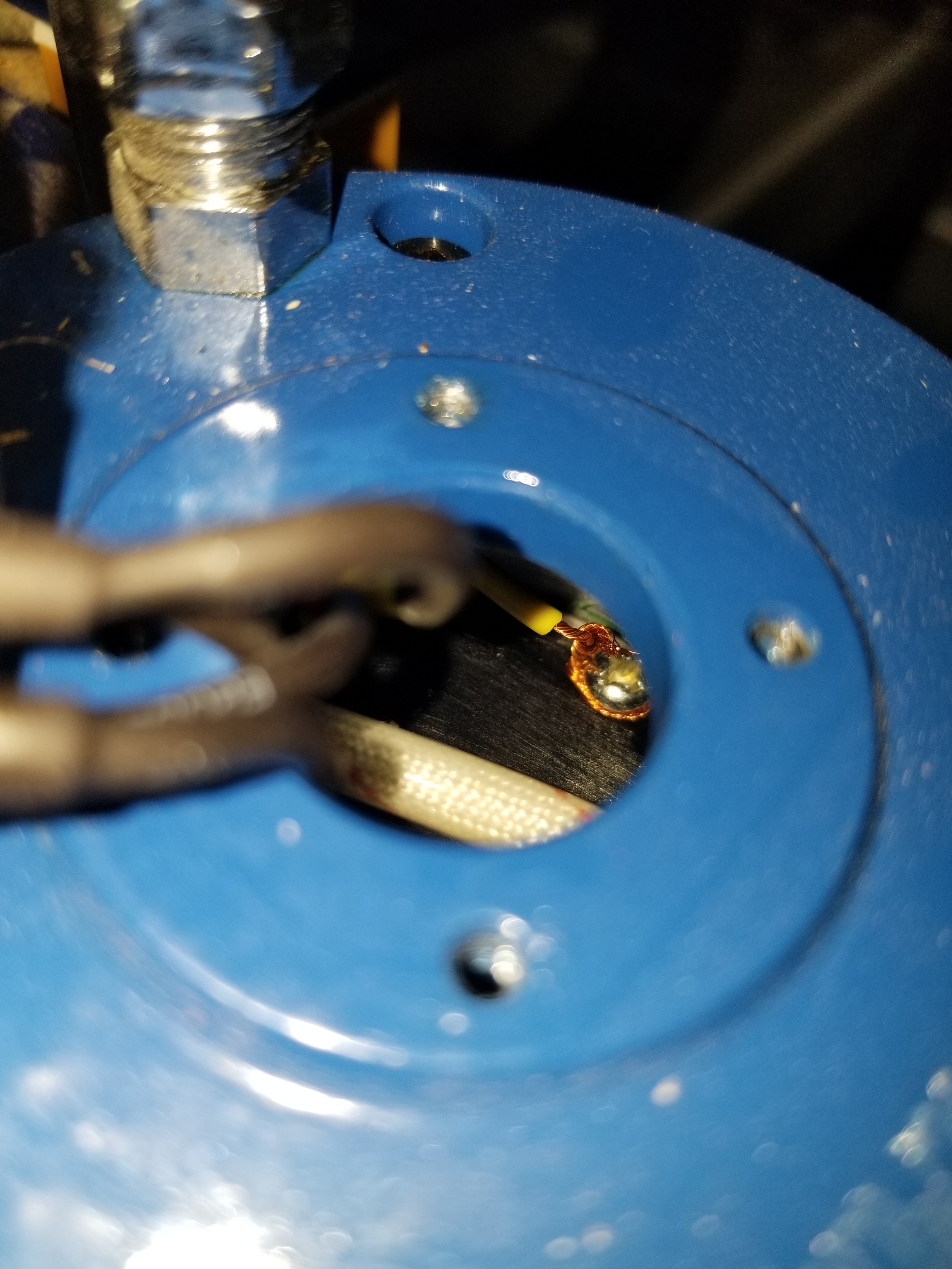
No - you should only use the green ground wire in your 3-4 conductor power cable and their connectors for VFD grounding. Have you checked to see that your spindle’s metal housing is properly grounded (i.e. connected to the VFD’s ground terminal through the ground pin on it’s 4 pin connector)? “Then I opened that connecter at the top of my spindle. Ground pin was not connected to anything!” You can also check it with your VOM.
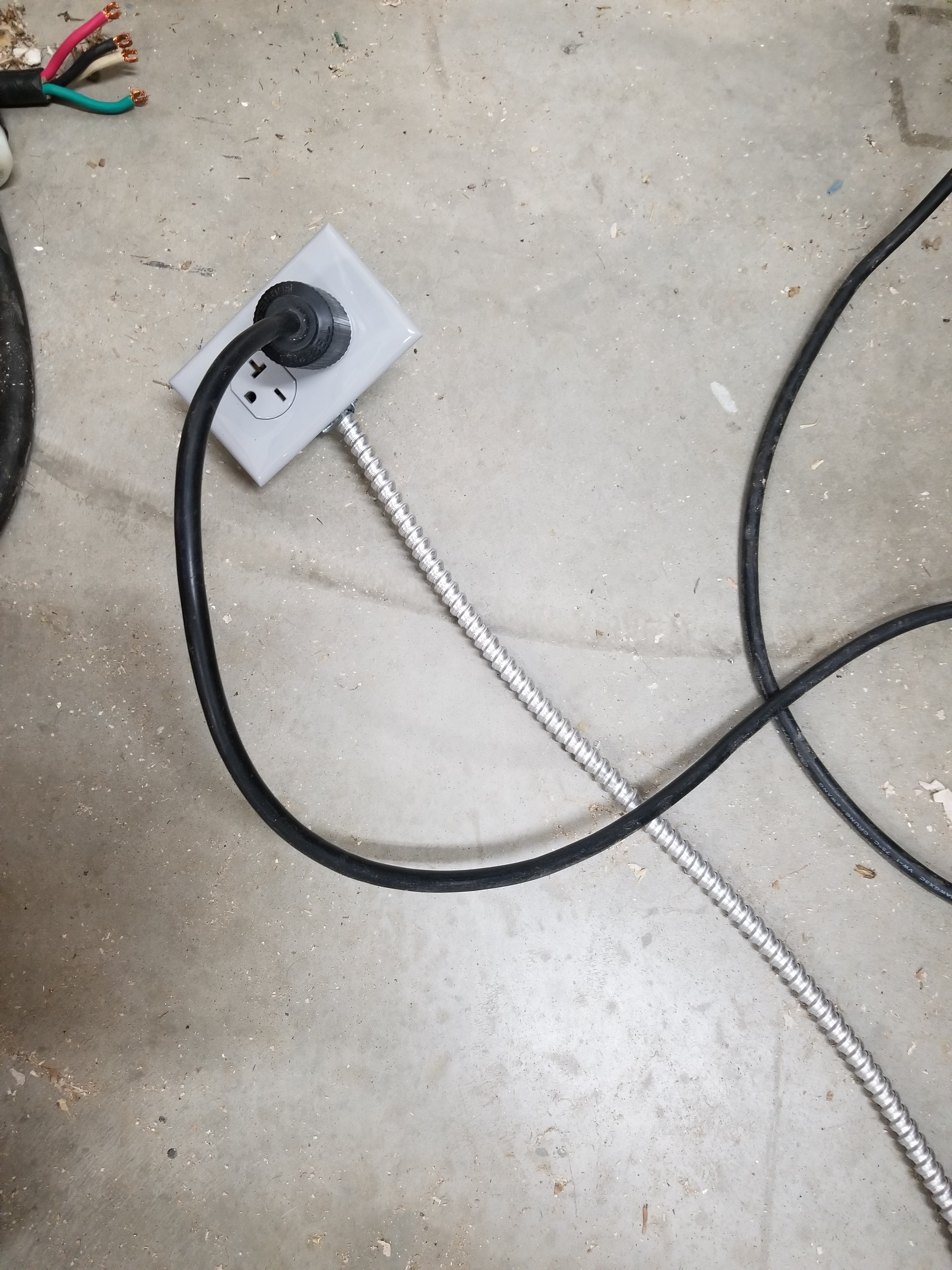
I removed the outlet from the steel wall and all metal screws/clamped holding it to the wall leading to the panel. So, now I have the metal conduit ran out of the panel, out in the floor and not touching anything else. This is the only outlet on this circuit. I still have the vfd disconnected from the cm board. I started cncjs, homed the machine picked toolpath, started the spindle, disconnected.
Did you ensure that the spindle housing is grounded?
What resistance do you measure (with your VOM) for each of the motor windings and the windings to ground (with the 240V circuit breaker off!) at the VFD terminals?
Resistance U to V?
Resistance U to W?
Resistance V to W?
Resistance U to E (VFD ground)?
Resistance E to spindle’s/motor’s metal housing?
Does the spindle seem to work properly as you manually vary its speed? Have you double checked your VFD settings?
What connections and input voltages do you now have at the VFD (another picture?)
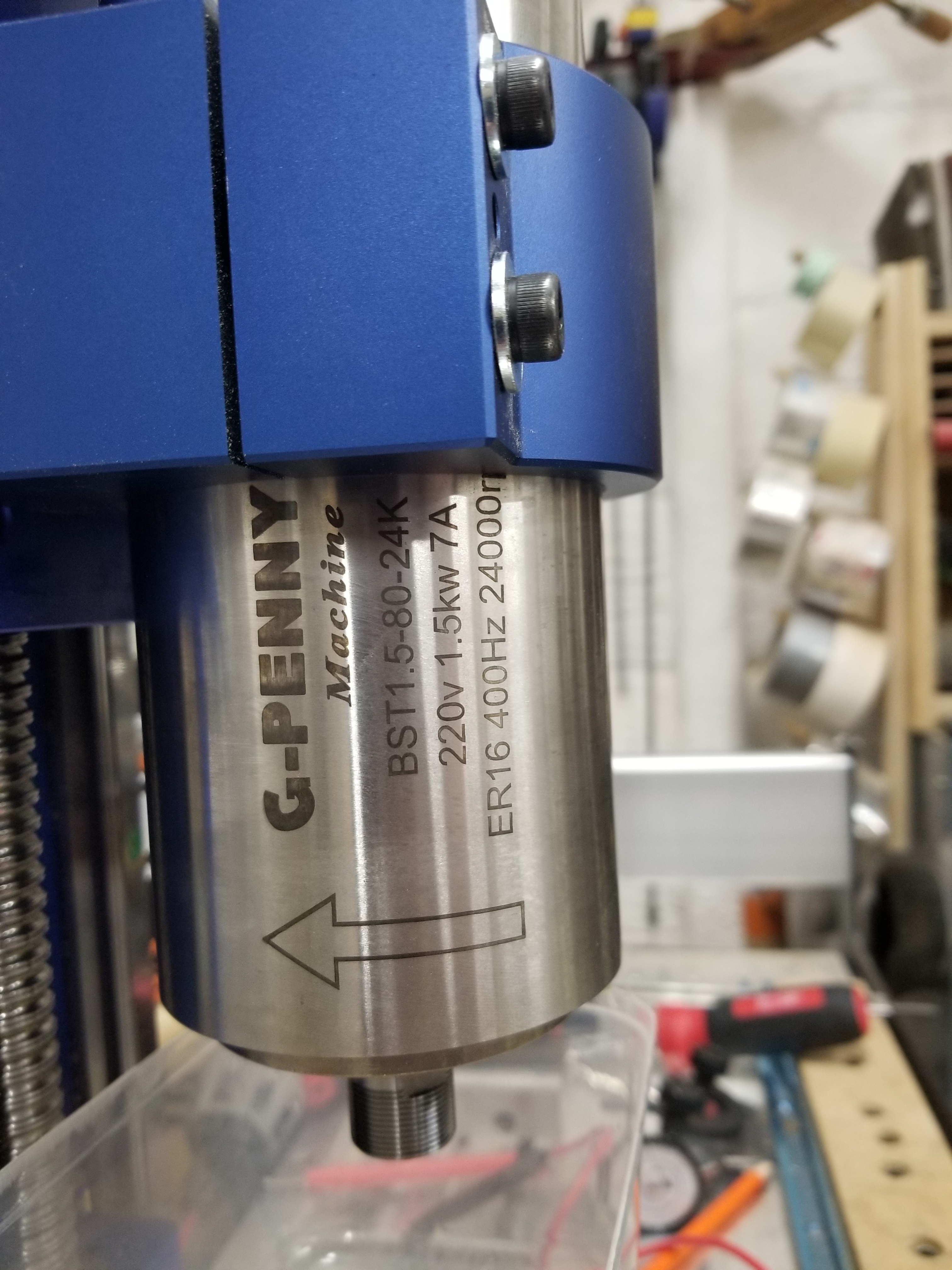
Post a picture of the label on the Spindle?
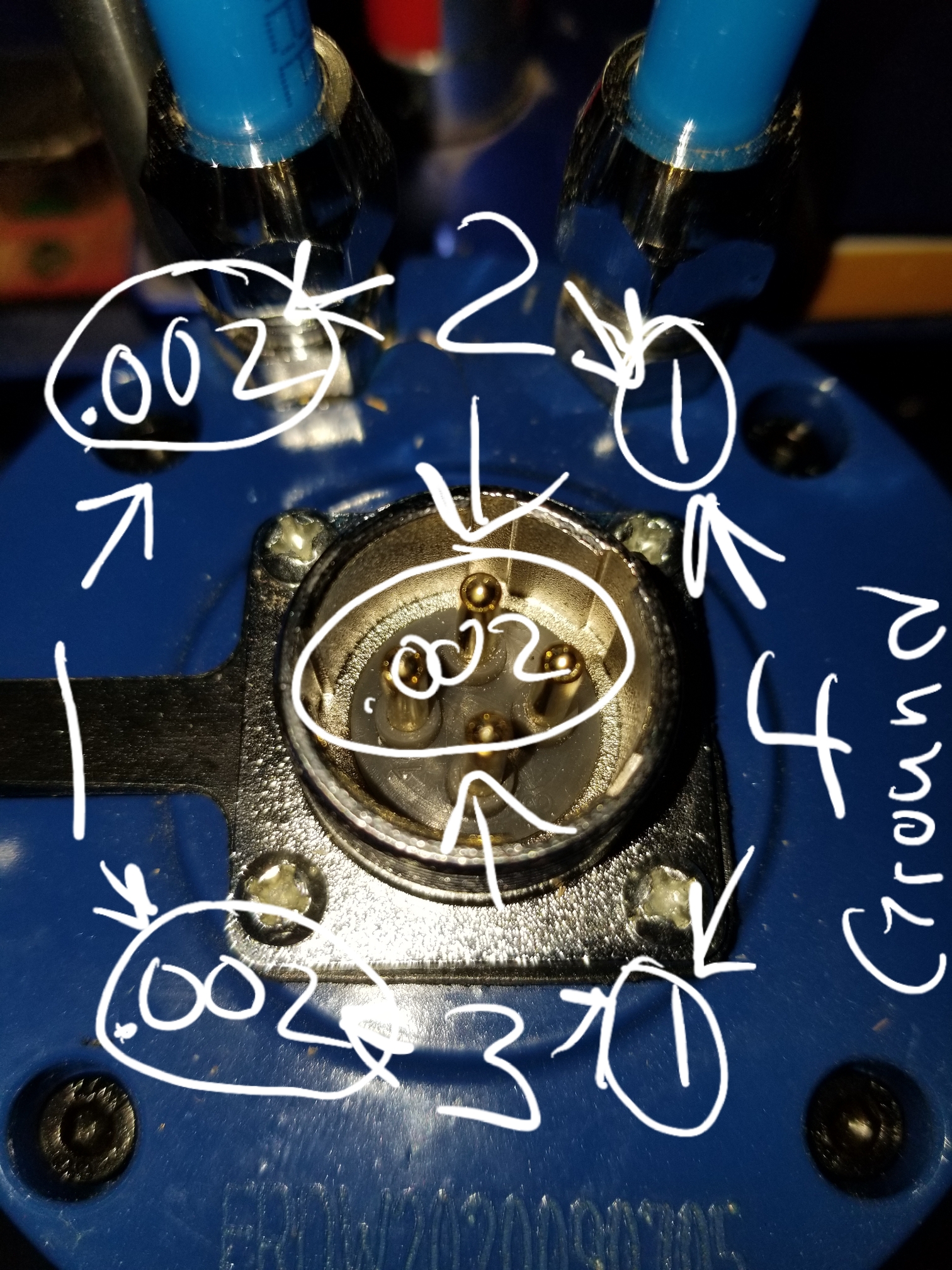
Resistance U to V?.002
Resistance U to W?.002
Resistance V to W?.002
Resistance U to E (VFD ground)?1
Resistance E to spindle’s/motor’s metal housing?
.000
Does the spindle seem to work properly as you manually vary its speed? Yes
Have you double checked your VFD settings? Yes I did, I looked at Juliens post to verify, the one setting I was confused on was the number of poles though, his says 2 and so that’s what I put on mine.
I was hoping for resistance measurements at the VFD terminals with the spindle connected (and circuit breaker off for safety).
PD141 = 220 spindle rated voltage?
PD142 = 7 spindle rated current?
PD143 = 2 pole motor?
PD144 = 3600?
R-S Should be ~ 240 Vac
R-E Should be ~120 Vac
S-E Should be ~120 Vac
I will need to take the cap off the top of the spindle for this, correct?
No, check the resistances and voltages at the terminal strip in the VFD as you’ve shown here.

PD141 - PD144 are the parameters you should have entered into your VFD.
Resistance U to V?.002
Resistance U to W?.002
Resistance V to W?.002
Resistance U to E (VFD ground)?1
Resistance E to spindle’s/motor’s metal housing?0
Those values look strange to me, I would expect something in the order of a couples of ohms between each phase (U to V, U to W, V to W), and a very large value (Megohms) between any phase and ground/body/earth.
Can you check your voltmeter by measuring a known resistance you may have lying around?
1 Like
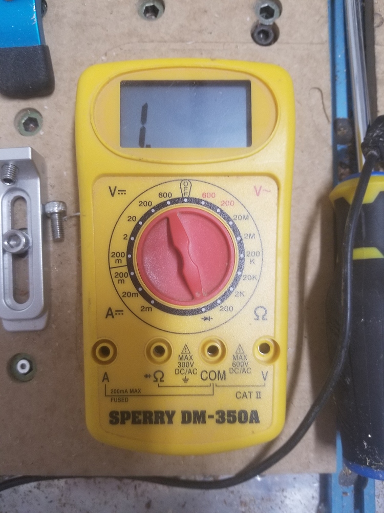
Yeah it’s in diode measurement mode, which is not correct.
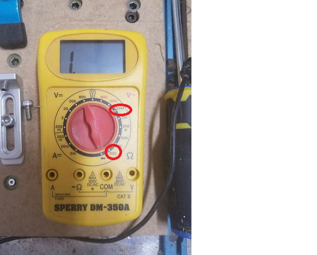
You should put it in “200” ohm mode for U to V / U to W / V to W measurement,
and 20M for U/V/W to body/earth
and plug the probes between “Ω” and “COM”
2 Likes