I find that if one adjusts the Depth per Pass so that only a very final shallow pass is made things work out pretty well — say if cutting to a depth of 0.5" with a Depth per Pass of 0.125" which results in 4 full-depth passes — reduce the Depth per Pass to 0.124" and one gets 5 passes, the ultimate of which only removes 0.004".
Alternately, draw lines, offset the text and the surrounding geometry and then use Trim Vectors to remove everything which is inside and assign a No Offset Contour toolpath — if you’ll upload a file we can walk through that with you, or maybe a Facing toolpath?
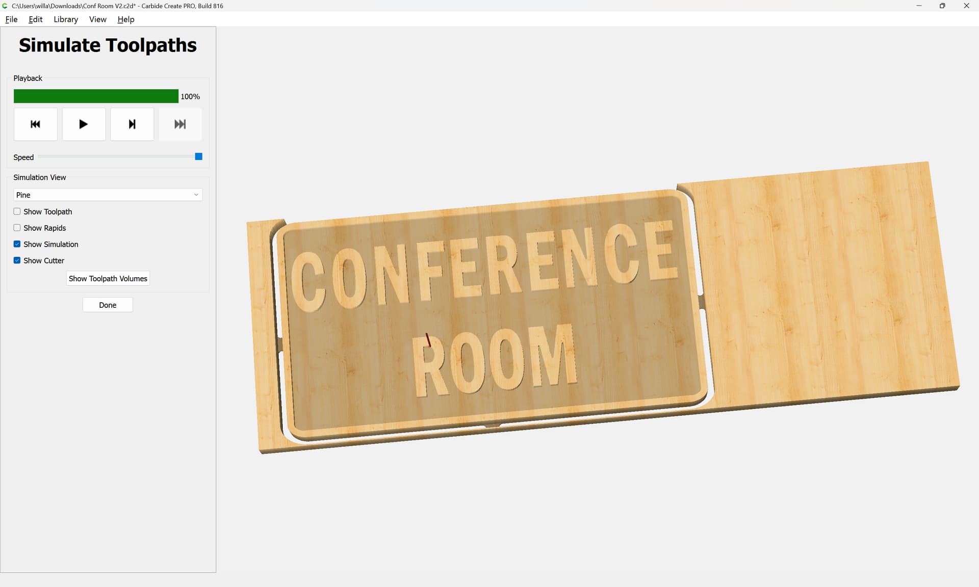
I attached the file. I am using a downcut bit because the church wants light colored lettering over a dark background. I have used a solid color stain over the wood before any machining and want to avoid/minimize any tear out around the letter edges. I have tried switching to straight and upcut bits for finishing passes and it doesn’t seem to make any difference. I originally set the initial cut to a depth of .195 and made a finishing pass of .005. It didn’t seem to help much.
The wood is Red Fir.
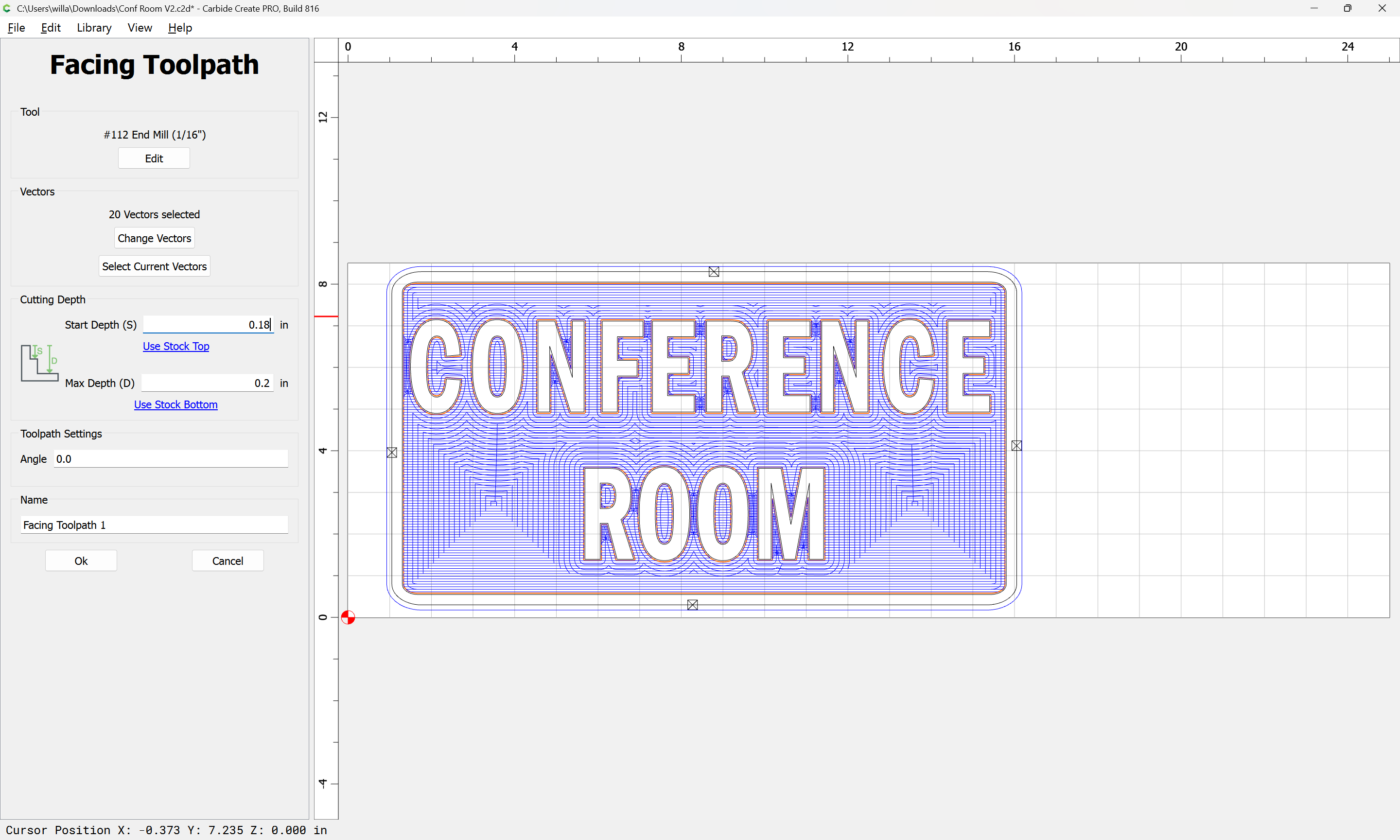
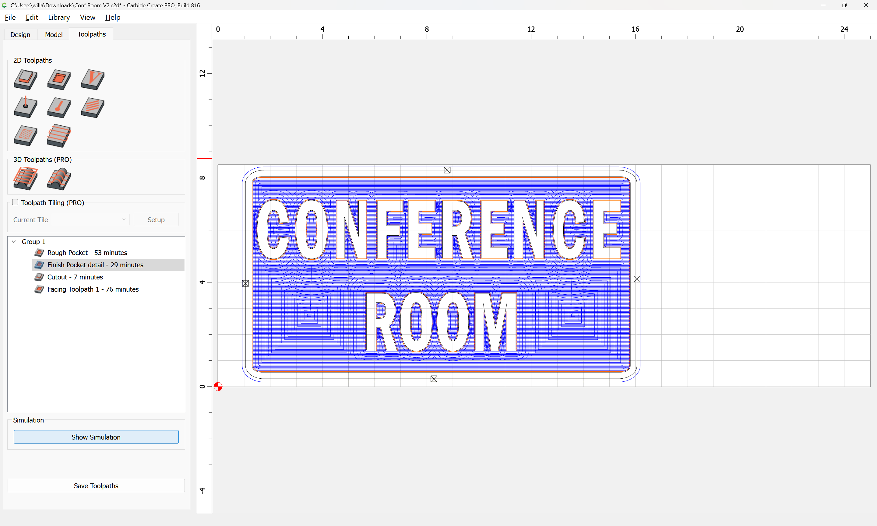
Is there a way to to Rest Machining with a facing toolpath? Conf Room V2.c2d (256 KB)
The initial pocket toolpath should be at most the desired depth minus (desired chipload adjusted by the greatest deflection you are seeing) — I usually assume the latter two values cancel out and leave things as they are — usually rubbing isn’t an issue — if it is, adjust.
I am trying to understand. If the idea is to minimize the swirlies around the letters and my initial pocket toolpath is set to my final desired depth of .2, what is there for the facing toolpath to clean up?
I noticed you had set the facing toolpath to start at .18 which is why I was asking if the initial pocket toolpath should stop at .18.
If you aren’t getting noticeable defects to clean up, then yes, pull the initial toolpath back by the desired chipload, then run the Facing toolpath (and an interior perimeter contour before-hand) as a finishing pass.
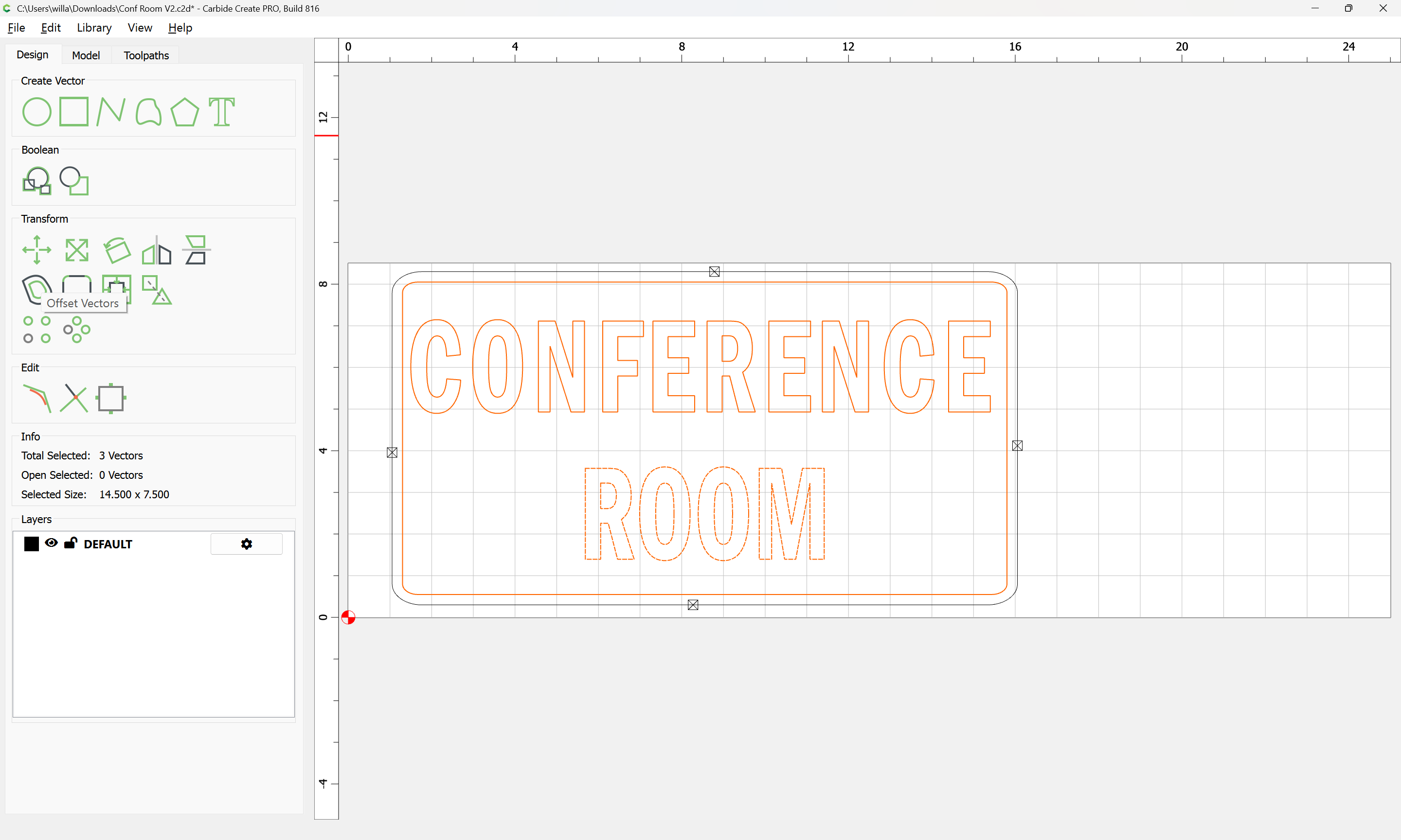
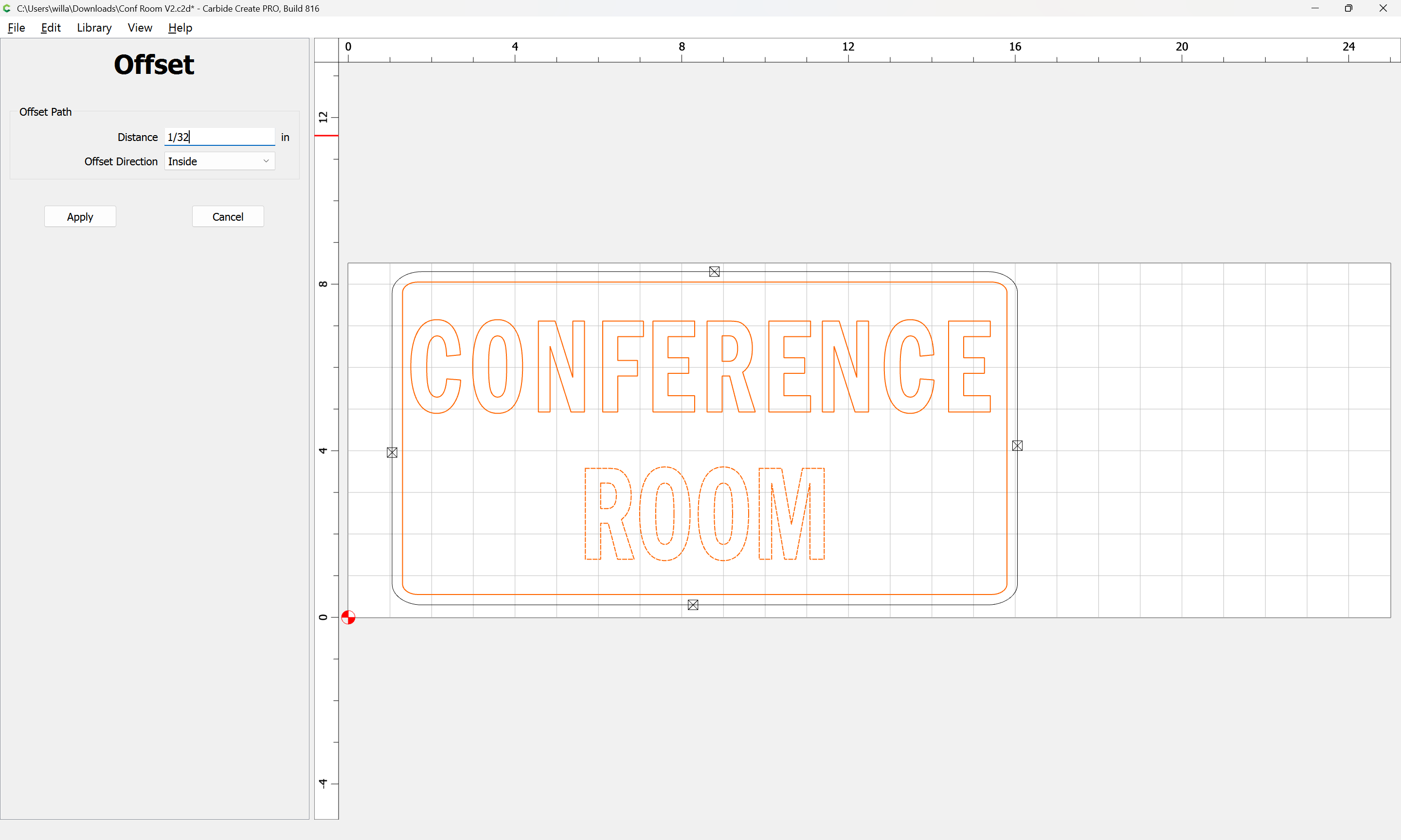
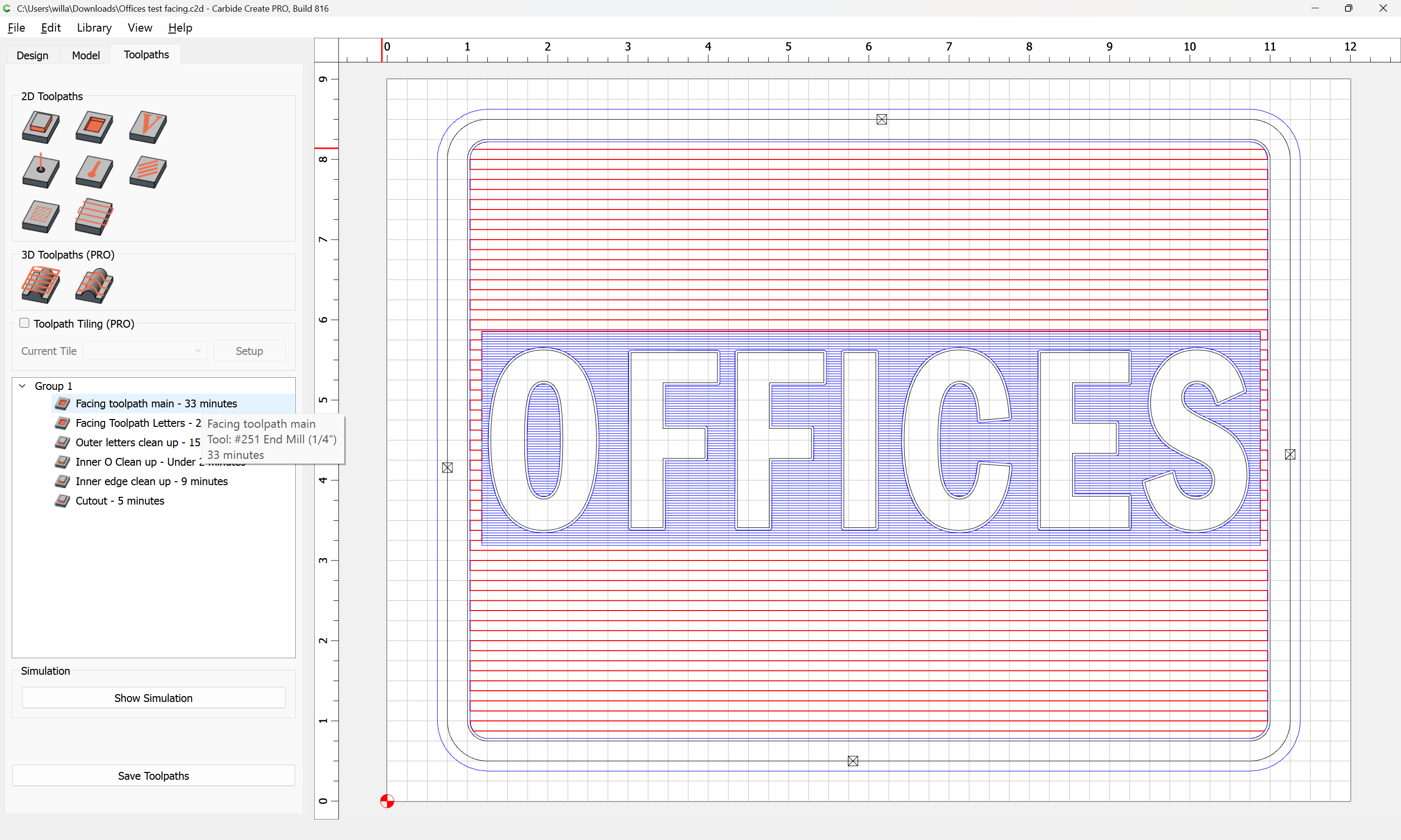
If someone can, I would love a critique on the attached file. To avoid the swirlies around the raised lettering, I followed Will’s advise and set a 1/32 inner offset around the inner perimeter and used a facing cut. No swirlies, but it also cut into my letters a small amount.
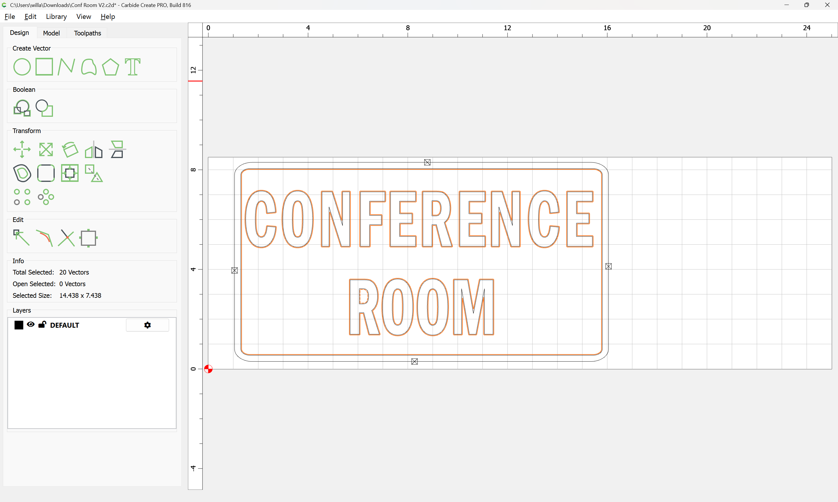
I have since added a 1/32 inch inner and outer offsets around the letters and added a rectangle containing all of them and created an additional facing toolpath within the rectangle to minimize cut time.
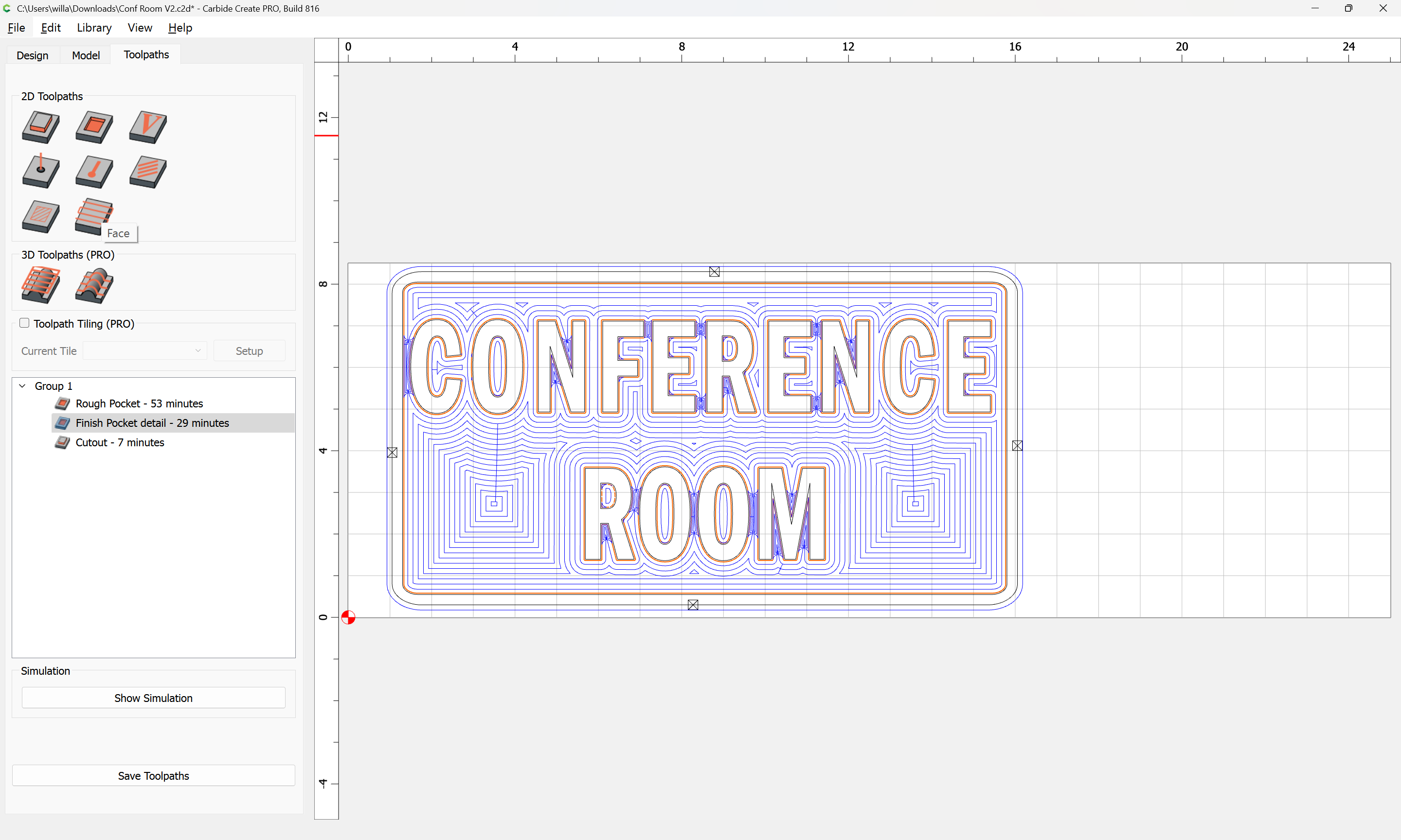
I then added a no offset contour offset path around each of the letters to clean up the edges as well as one around the inner perimeter.
When I look at the simulation, the left and right borders appear to be narrower than the top and bottom borders.
Due to the long cut time, I would appreciate and critiques. I have pushed myself well beyond my limits and my brain hurts. Offices test facing.c2d (192 KB)
Suggestion: Change the offset for the 1/4" tool to 0.130 (half plus 0.005"), change the offset for the 1/16" tool to 0.035". Use the 2 offsets to contain your 1/16" path, rather than a rectangle.
Cut the facing paths to 0.200 deep. These will leave 0.003-0.005" finish stock on the walls.
Now profile/contour the walls directly with an offset so you can climb cut. Do the finish cuts at 0.198" deep, this way they are not leaving marks around the letters & just cutting the walls.