Power Hacksaw is Complete!

First the Video:

This design has a total of 38 part numbers, 22 of which were machined on the S3, 10 were hand made (Hack saw, and drill press), and 6 were eliminated. An example of some the parts I eliminated were things like the Vise handle and Vise handle caps, which I used a 5/16 long bolt, cut to length and to 1/2 balls welded to replace the handle caps. Four (4) parts to hold the Rod to the crank and blade holder were replaced with 2 shoulder bolts (eliminating two Lathe parts. I did need to remove the threads from the shoulder bolts and then drill and tap for 2 retaining screws.

The original design requires a Lathe and Manual Mill, but with some out of the box thinking (like as mentioned above), every machined part can be made on the Shapeoko with the exception of a small modification to the threaded rod. I modified that particular part using a Drill Press and a small hand grinder (details below). The $10 design from eBay user myfordboy supplies you with 2D drawings, that I then turned into 17 3D Solid Models in (Fusion 360) OR 2D cut sketched in Carbide Create, 5 parts). PS He has sold over 800 drawing, and I was the first to spot to design errors.

As always, let me know if you have any questions

.

.
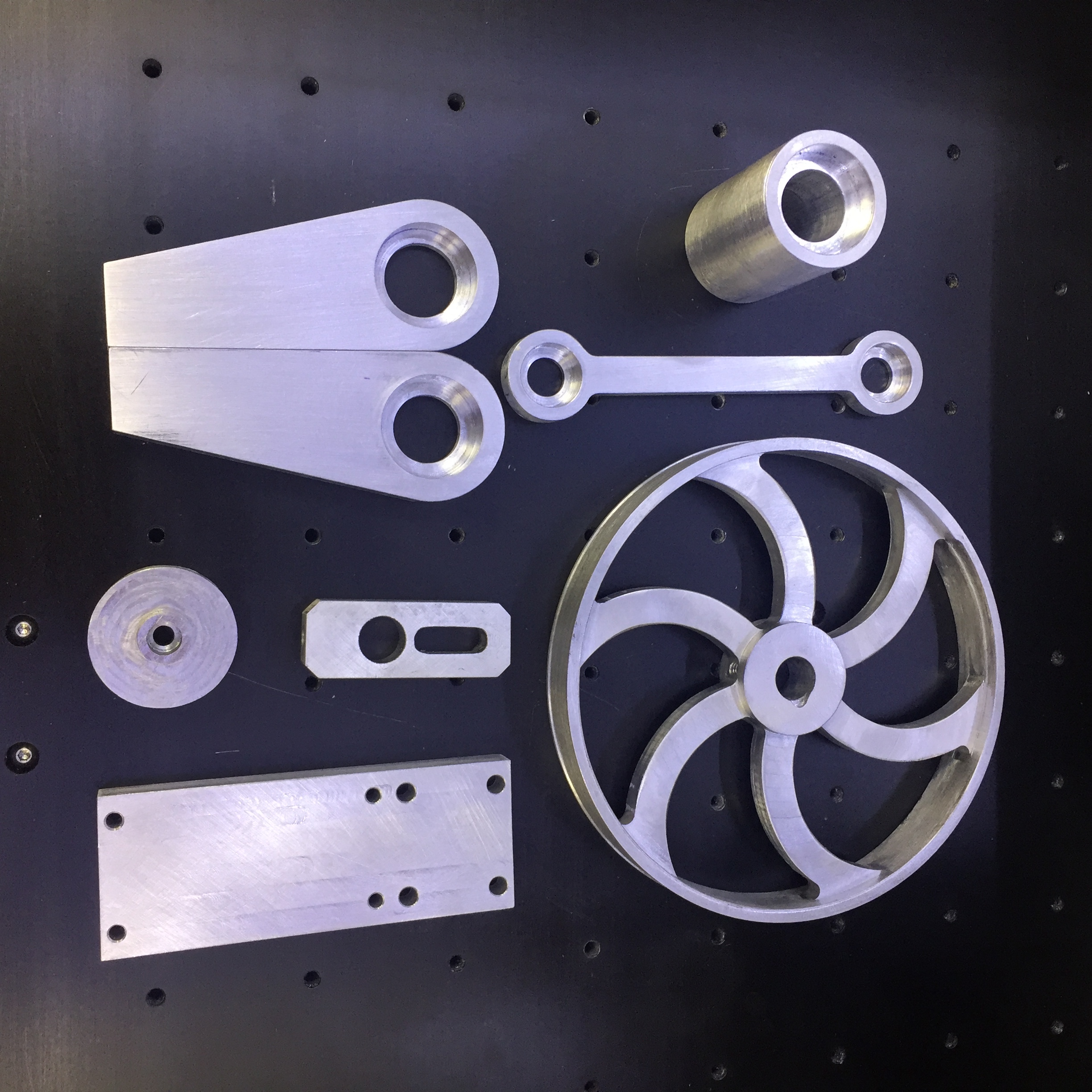
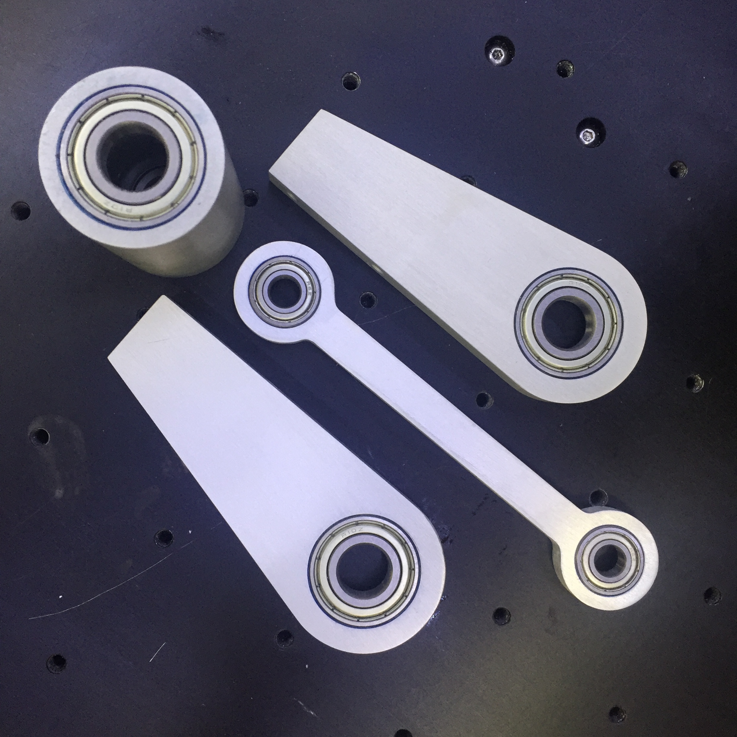
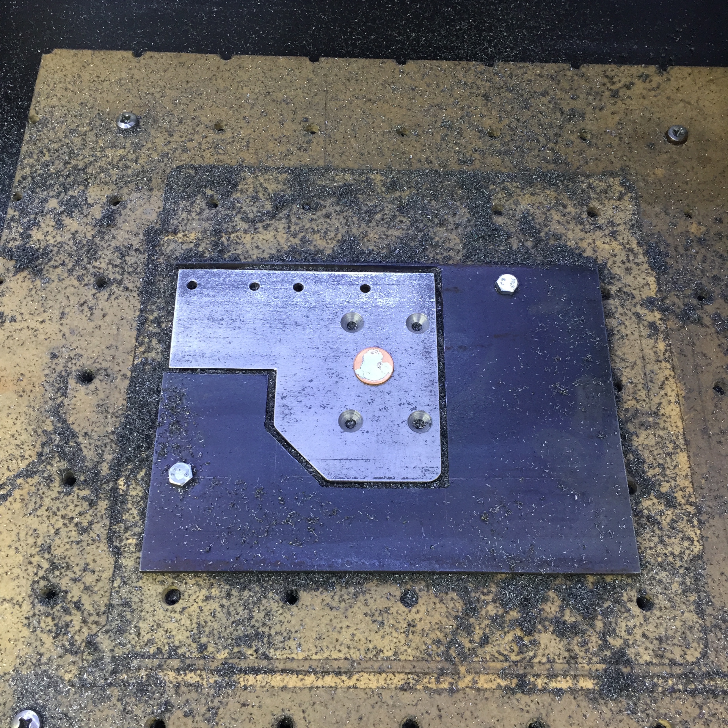
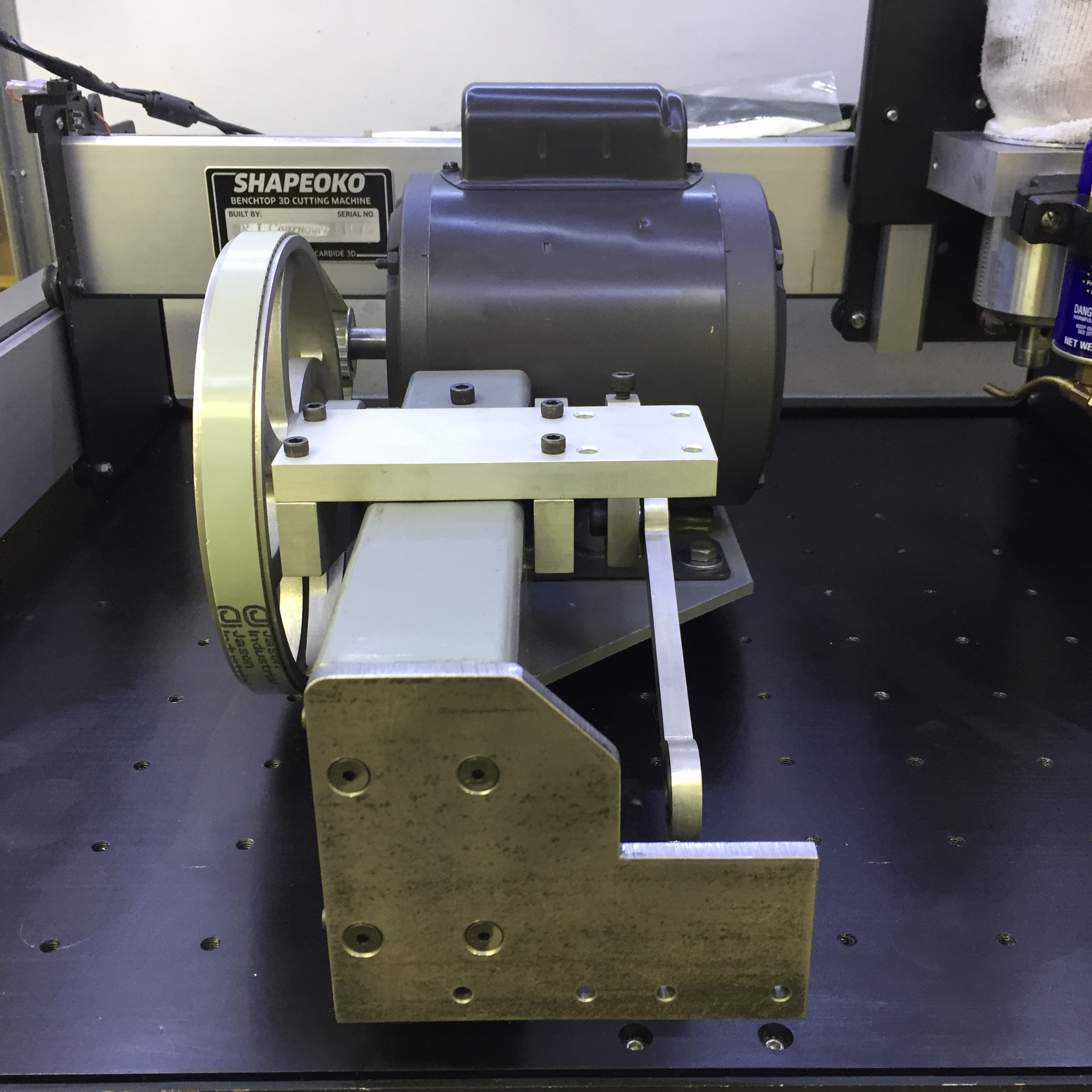
These are the only aluminum parts (except for the pulley guard), and they are the critical parts since almost all of them had tight (press fit) tolerance bearing bores or slip fit bores. Clearly the pulley did not need to have the S-shaped spokes, but I’m a sucker for antique flywheels, and that was my design inspiration.


.

.
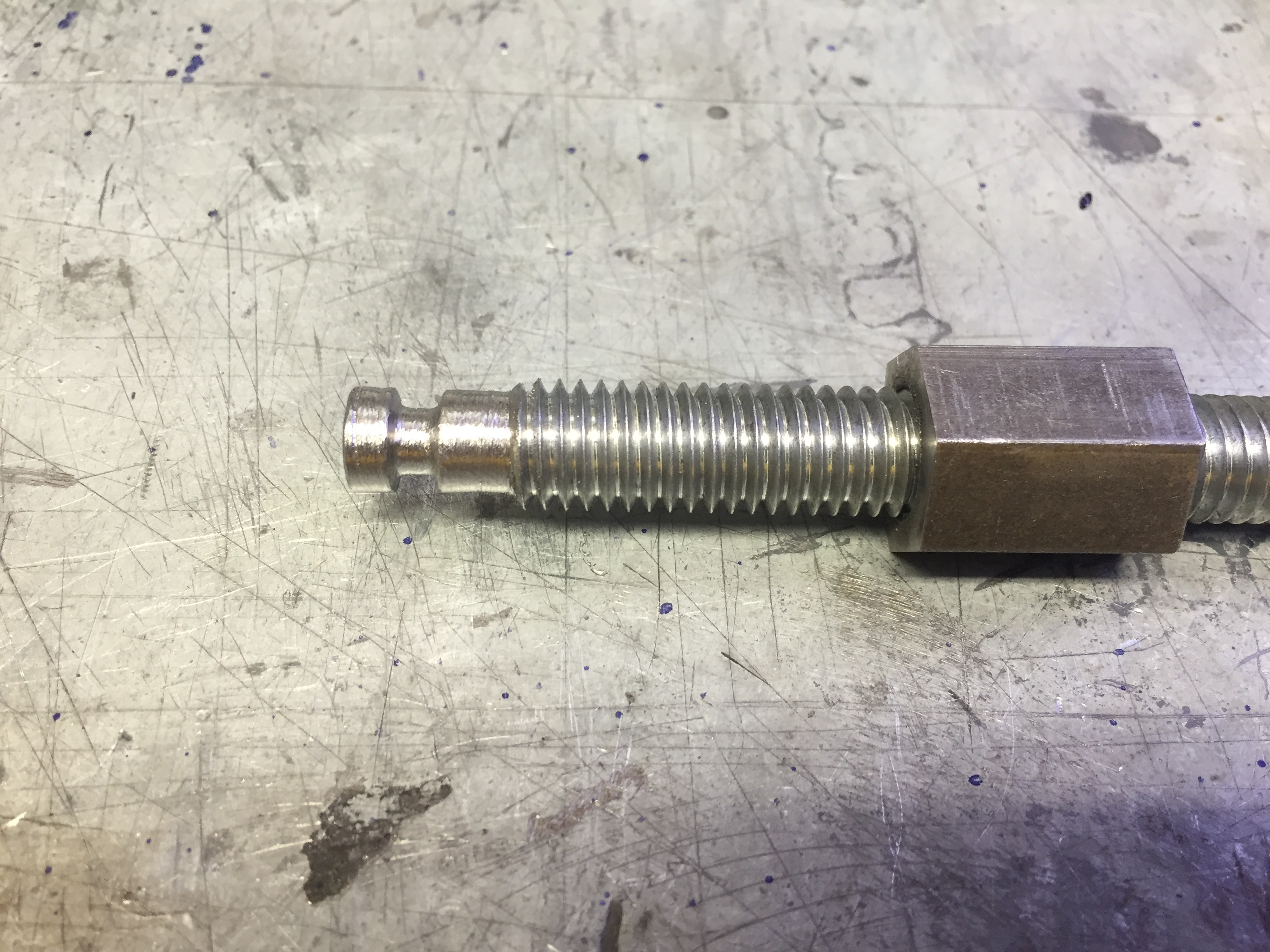
This is the one part that needed a lathe. I cut my part about an inch longer, chucked it in the drill press, and used my hand grinder to grind an OD and undercut for a roll pin. I then machined the mating part once I established the sizes on the drill press.


.
.

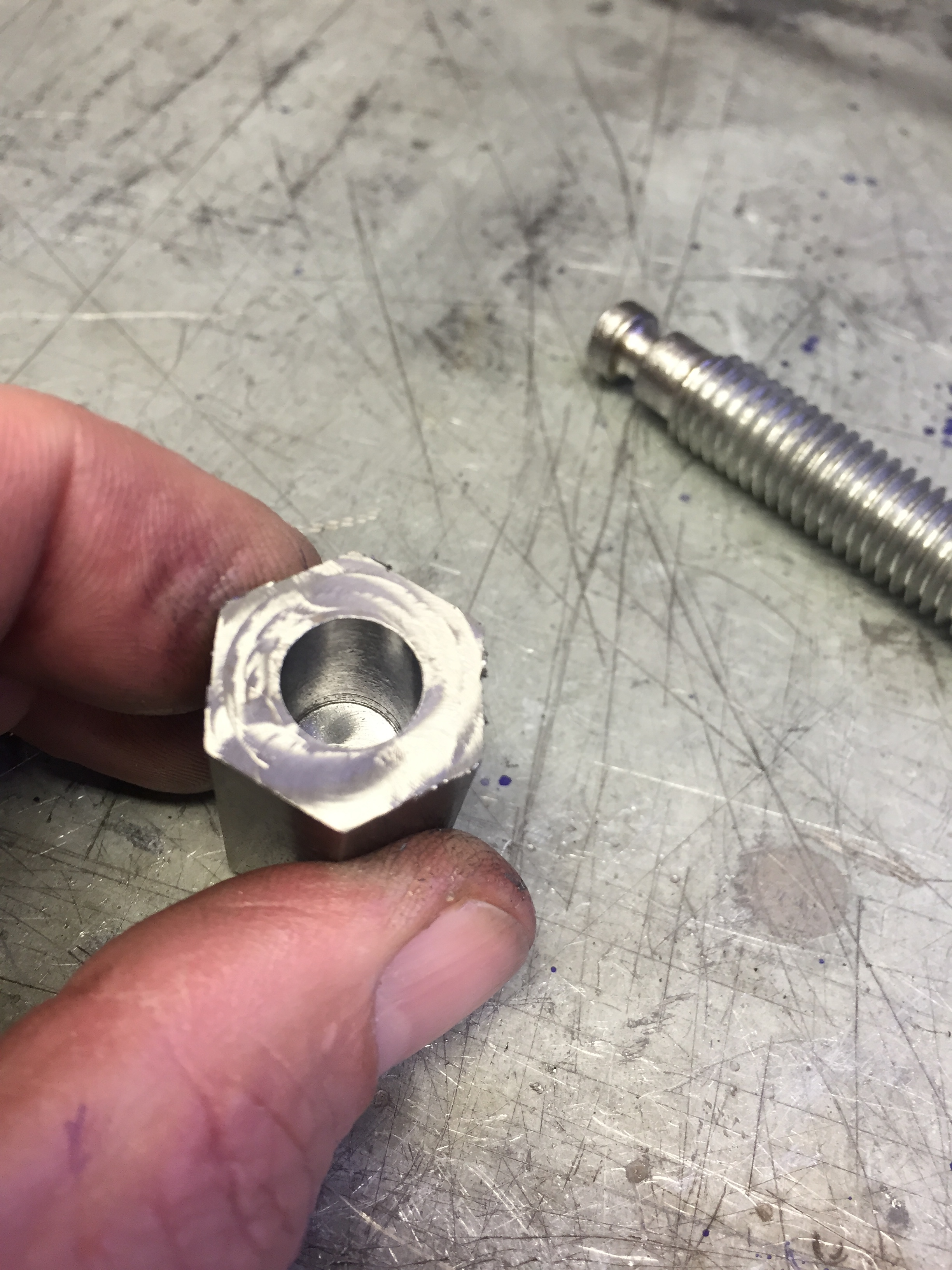
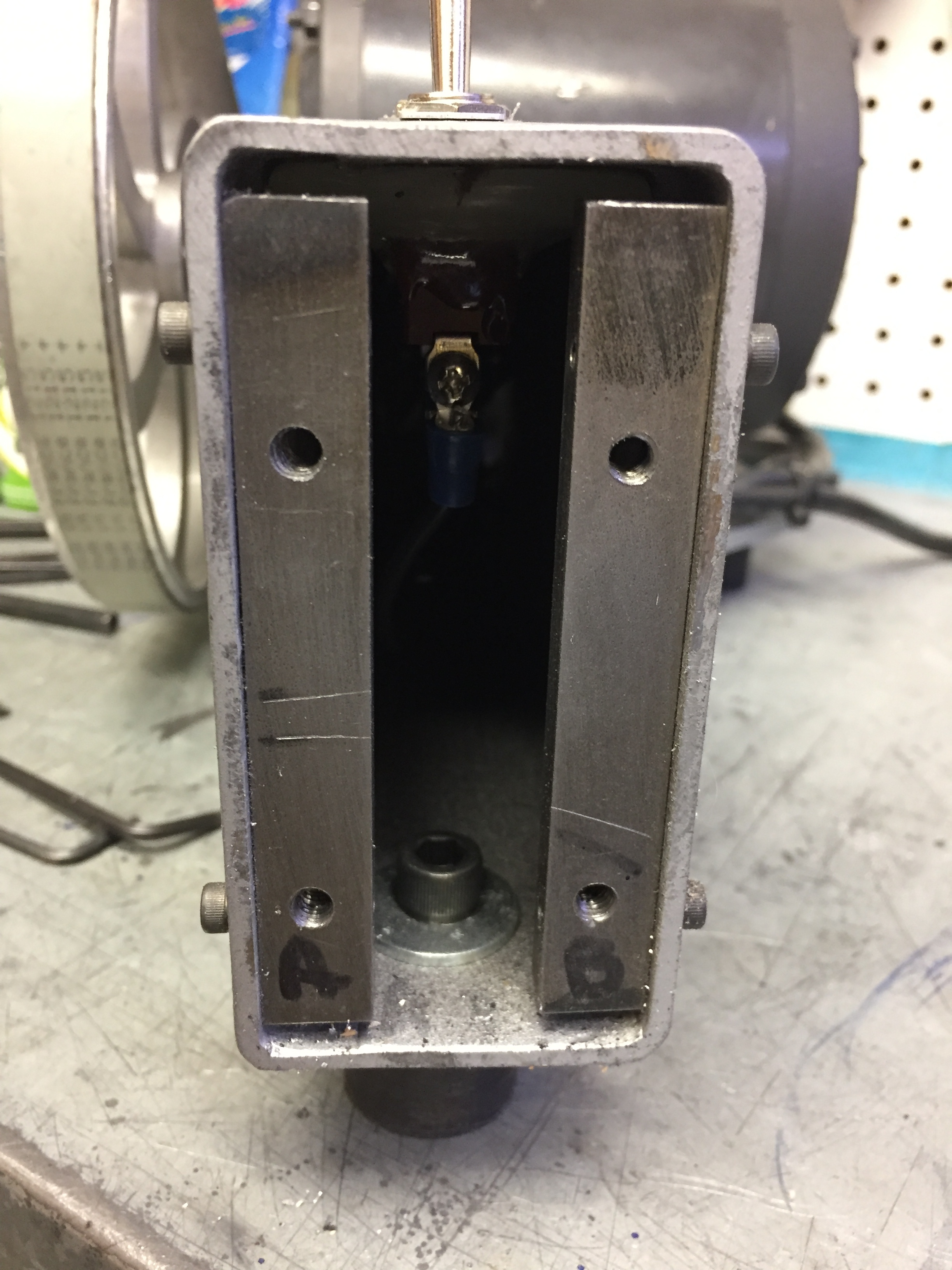
The Hex design of the sliding surfaces (Saw and vise) allows for the 60º sides to act has the rails against each other providing a smooth flat bearing surface for years of use. The adjusting screws are held in place with Loctite (Since they are not very tight).

.

.


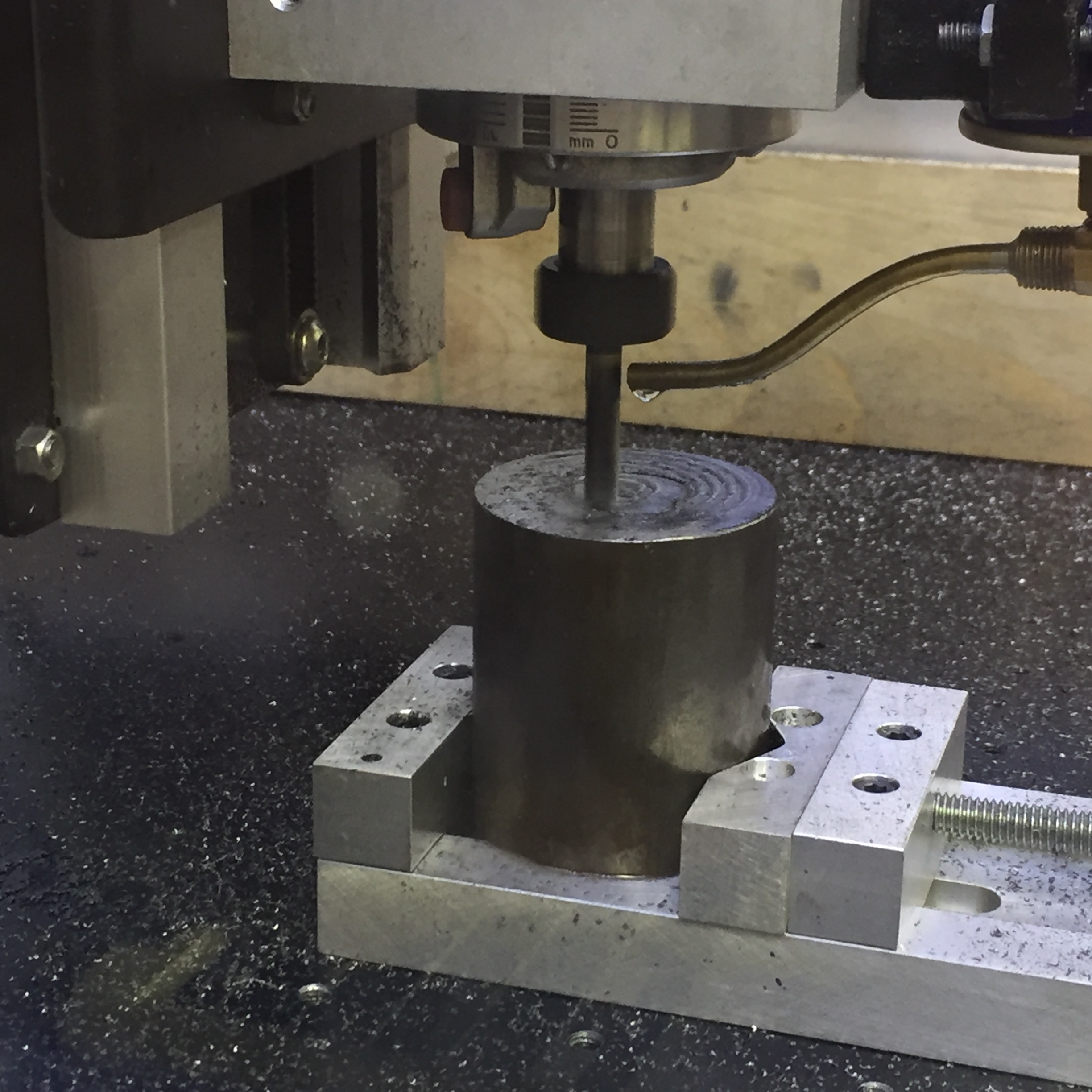
Counter weight is what helps provide the cutting force for the blade is being faced to length here…

.
.


Some of the steel is hot rolled with an ugly HARD surface crust, so rather then waste expensive end mills I bought some $1.20 Carbide end mills (2 flute, 1/8 dia) for this project from BangGood. I only used 4 of them for all the steel parts

.
.


Here is a typical example of a hand made part. These two inner braces, were laid out, hand cut and matched drilled from the 2X4 tube.

.
.


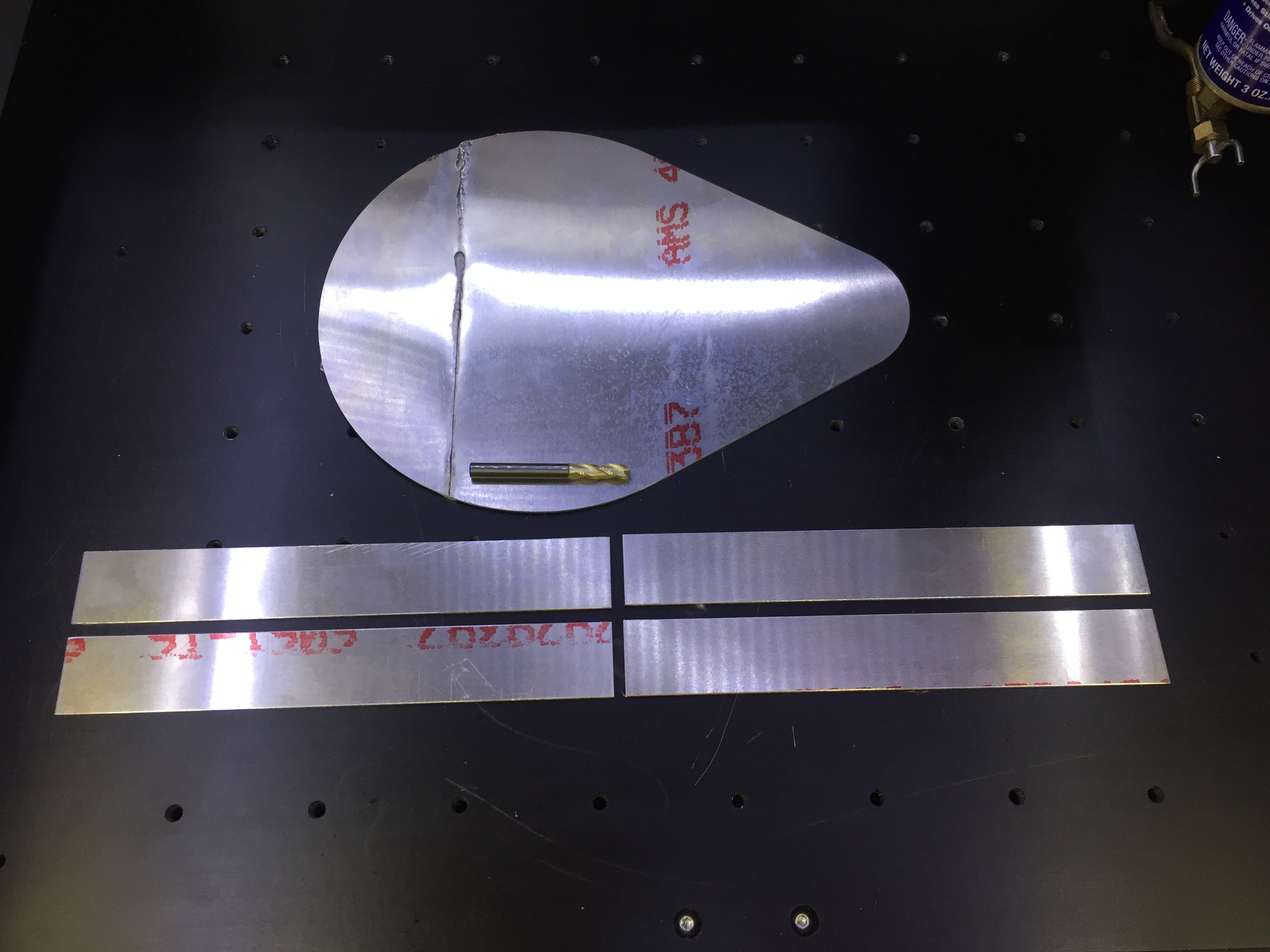
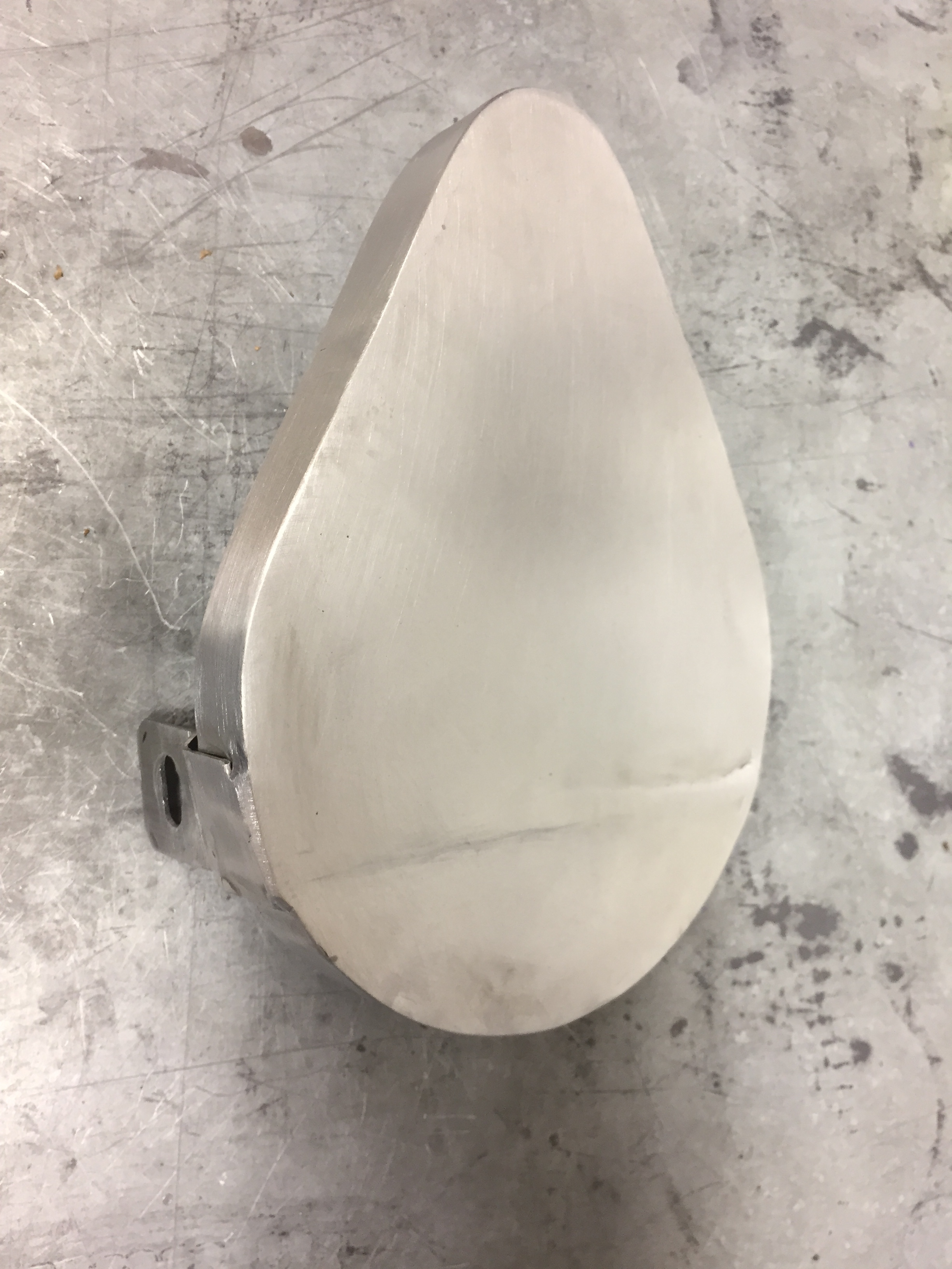
The pulley guard is made from 8 separate pieces of aluminum and then TIG welded together. The original design calls for 1/4 wood and aluminum flashing, but I thought this was a great time to re-teach myself how to TIG weld aluminum (I welded it a few time back in the late 80’s)

.

.
Cost (about)
Material: $64
Motor: $39
Bearings: $26 (I have plenty of spares)
Hardware: $18
Blades: $15.60 for 12 ($1.30 each) Starrett HSS (Lasts for weeks)

Well that’s all the exciting parts to this fun project. I started 6/22 and finished 10/10 while recovering from Rotator Cuff Surgery…what a great way to keep my mind off the pain… Let me know if you have any questions

16 Likes

Hey this is awesome! It looks great!
Just one comment, it would be great to be able to adjust the length of the stroke to reflect the width of the stock while still allowing the maximum stroke. It looks like only one part of your blades is getting used so they will wear out faster than needed.

1 Like

The length of the stroke is actually adjustable and it’s easy enough to use a piece of wood in the vise to transfer the cutting to and a new section of the blade. Or you can flip the blade. I tried cutting with the teeth forward and aft during testing last week and didn’t see and difference in quality or speed.

4 Likes

I still really want to make something like this to cut logs into boards. I’m thinking a frame saw and a slower stoke speed would work, maybe even multiple blades at once. So many ideas so little time though.

https://www.youtube.com/watch?v=nSf-JL8EDvg#t=31 but DIY lol

2 Likes

Nice work sir! Hopefully some day I’ll get that good at milling. Very inspiring indeed.

2 Likes

Yeah, that’s some of the most extensive aluminium milling I have seen done on the carbide machines. Very impressive indeed and inspiring. I want a shapeoko now.

2 Likes

If your a maker the shapeoko is the best for the price. I have about $1,500 - $1,800 with limit switches, homing block, aluminum base, and laser. Although the Tormach PCNC440 looks fairly solid, and may be my next choice. @edwardrford runs THE BEST customer service in the business, and YES it is better then inventables. I’ve been able to mill aluminum, but don’t go to @RichCournoyer’s extent.

2 Likes

Incredible project and incredible work @RichCournoyer. Thanks for sharing your project and your knowledge with the community.

1 Like

Sorry such an old thread. Great project. @RichCournoyer how did you cut the slot around the perimeter of the pulley for the belt to ride in?

2 Likes

Per the drawing…the large pulley has no slot…it’s a smooth pulley. Not something I would normally use for a timing belt, but the designer states that there is enough surface area to provide enough grip (for the belt); and he’s right. The belt has NEVER slipped. Learn something everyday…

PS He also states that a small V-Belt pulley (on the motor) would not have enough surface area to work…meaning that belt design would slip.

2 Likes

For a similar tool, be sure to check out:

I’m pretty sure the $200 credit has not yet been claimed — someone really needs to make one and show it off and get it.

Hi Richard.
I recently bought the pdf files from David. Even though I do own a lathe and a milling machine, I’m not very good at reading drawings.
Would you share or sell the Fusion360 files, please? I believe they will help me as to better visualise the parts.

Nick

Sorry, but I can’t share models of a design that I do not own, but I will give you some advice. Since you purchased the drawings, you’ll note that they are for metric material. If you are building it in the US with non-metric sized metal, you will need to move a few items to compensate for the difference in material size.

Richard, thanks for your prompt reply. I’m open to any help even though I see that it will take me weeks to even gather the materiaIs. I mostly work with aluminum and brass hence I’m not familiar with hex, steel plates etc.
The drawings I received contain both metric and imperial dimensions. This is not really an issue for me as I mostly use metric though my machines are all imperial! By the way I’m based in Athens, Greece.

Thanks
Nick

1 Like