I was asked if I could create a sign for a wedding. I thought it should be easy. They sent me a dxf file and a pdf file. They sent me the font file also. No matter what I do I can’t get the dxf file to load and show an image in carbide create. I also tried to save as svg But they open with no imae showing. I tried saving in several different svg types. So then I installed the font. In carbide I started to create parts of the sign becasue it is bigger than my shapeoko 3. The file I uploaded is the output of part of the sign. The letters overlap. Since the text is one object I can’t use boolean. So I tried to save the text as an svg file and edit it with inkscape. Inkscape is very difficult for me to erase parts of a line. Either it erases the entire letter or it turns all letters black with a white space where I erased part of the image. After several attempts I thought that I was able to erase the over lapping lines. But when I reloaded the image in carbide create the area where I erased the over lapping lines is all black. if I select each letter I can move the letters away and the black erase stuff says put. But I’m left with the original text with the over lapping. All I want to do is cut out the letters sys such that I have a single piece of wood.
What am I doing wrong?
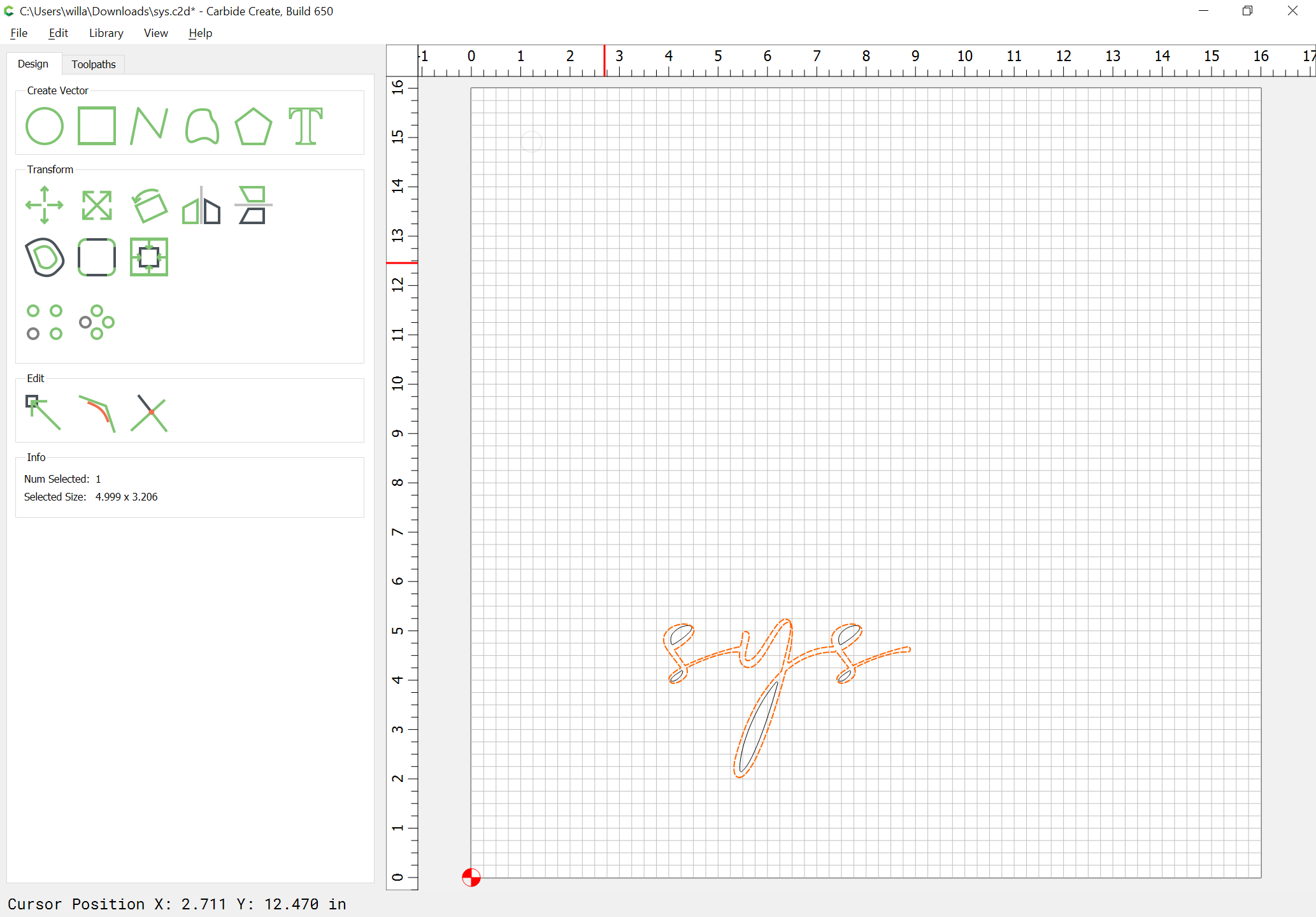
sys.c2d (257.9 KB)
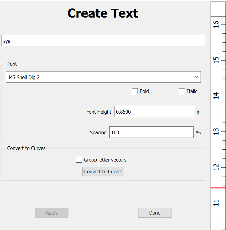
Check in the text tool to see if you have the option for covert to curves. If not update to a more current version of Carbide Create. Once you convert the text to curves you can then move the letters around and use Boolean Unions to join them as you desire.
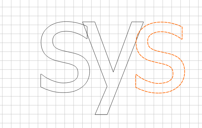
moved to have some overlap
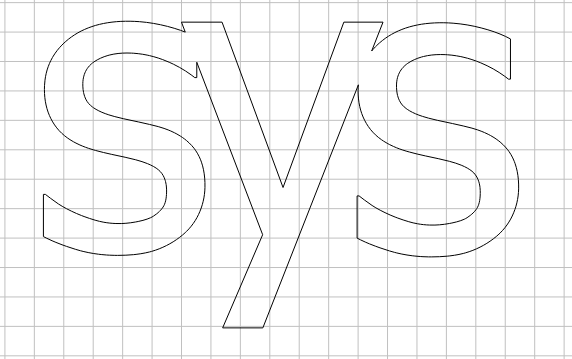
After a Boolean union
Carbide Create now has a function for spacing text but CC only creates text in a single line. Inkscape is quite complicated but what you are trying to do is called kerning in the printing industry. You want to space the letters more or less. Search for kerning in Inkscape.
I have Affinity Designer which has that features built in. I bought it half price and it was $25.00. I think the usual price is $50.00. The Affinity Designer lets you conform text on shapes. For instance you want to create text on an oval or circle. You can even create the text on a path that is not a closed vector like a curving line.
Not sure I understand the “single piece of wood” thing.
You control whether the letters are still attached to the base by setting the depth.
If you want to machine outside of the letters, you need to create a rectangle to contain the path.
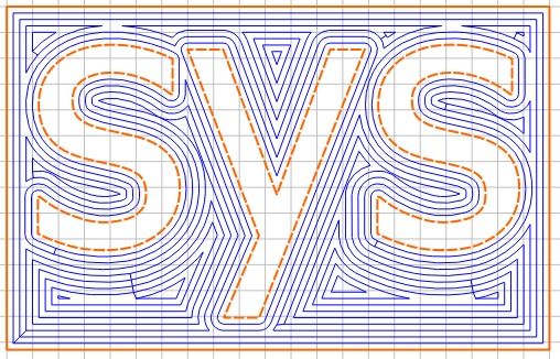
First, apply a Boolean operation to convert to paths, then, Boolean Union:

Update to v6:
https://carbide3d.com/carbidecreate/download
and see:
https://carbide3d.com/blog/merging-script-fonts-in-carbide-create/
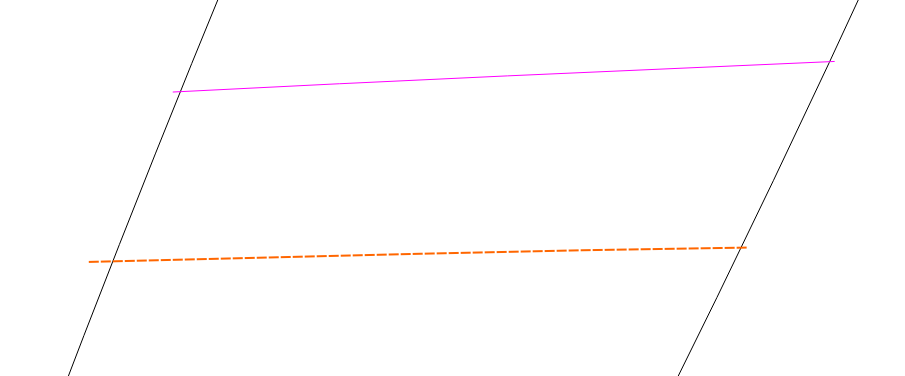
Thanks for the response. The version I was using was 413. The version 648 works much better. Was able to use the boolean feature to get rid of the over laps. But why does some of the lines show solid and some of them dashed lines. I will see if this will do the job.
Another question Why don’t the toolpaths show up when I click on toolpaths. Every time I click on toolpaths I get a new toolpaths. I can’t delete them. I ended up with 5 toolpaths.
I guess I have another question. Where is the settings tab? How do I set stock thickness?
What I’m trying to do is to contour cut outside of the letters. Your example shows separate letters. My will be connected.
Thanks for the reply.
Not sure what this kerning is but I was just trying to erase where the letters overlaped. Will Adams response fixed the problem.
Thanks for responding.
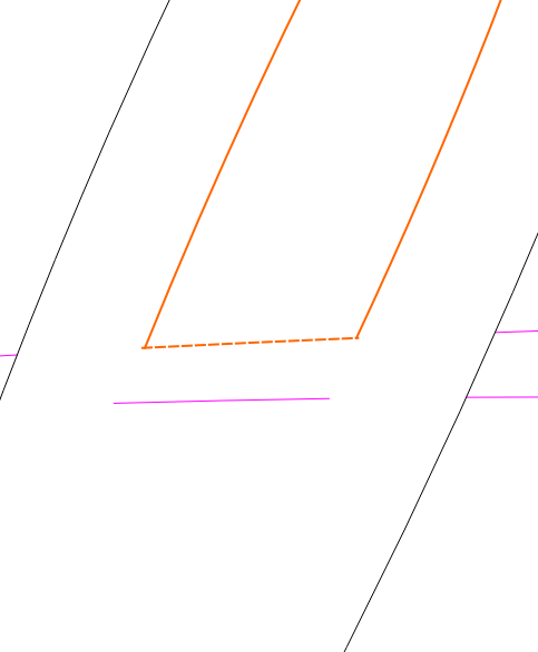
The most recently selected object is the key object, indicated by a dashed highlight.
Settings is Job Setup (gear icon):
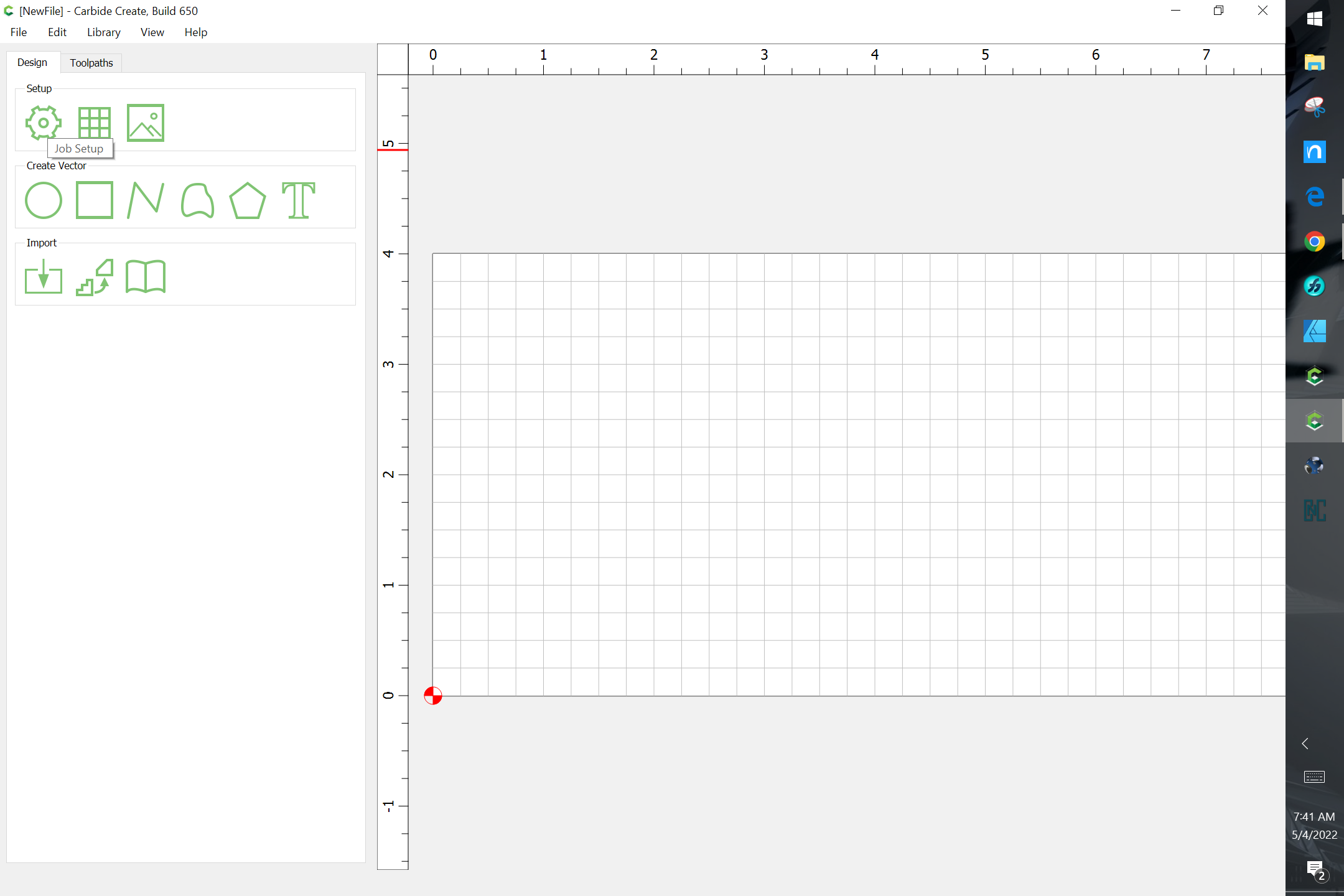
the icon only shows when nothing is selected.
I just opened carbide create and the setup icons show up and the toolpath also show up. Last night neither were showing. But because of the 5 toolpaths I didn’t save the file. Will try again later today
Thanks
I just found that the setup icons go away after I start design. Is there a way to get it back?
The setup icons only show when nothing is selected.
Click in a blank area of the screen to deselect to bring them back.
Right clicking on the toolpath will give you the option to delete it.
Thanks I didn’t notice.
Correct. But the toolpaths need to be displayed. When I had 5 toolpaths none of them were visible.
If you can come up w/ a repeatable set of instructions for causing the toolpaths to disappear, please let us know and we’ll do our best to look into this w/ you.
I’m not sure. It so far only happened the first time I ran version 648.
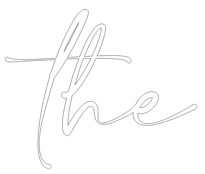
One additional question. Is there a way to make the pocket in the h two separate pockets?
No matter what I try the toolpath cuts the part of the letter t that goes thru the h
TheSign.c2d (238.5 KB)
- First, make a copy of the interior vector of the ‘h’
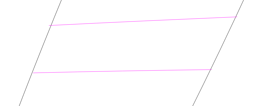
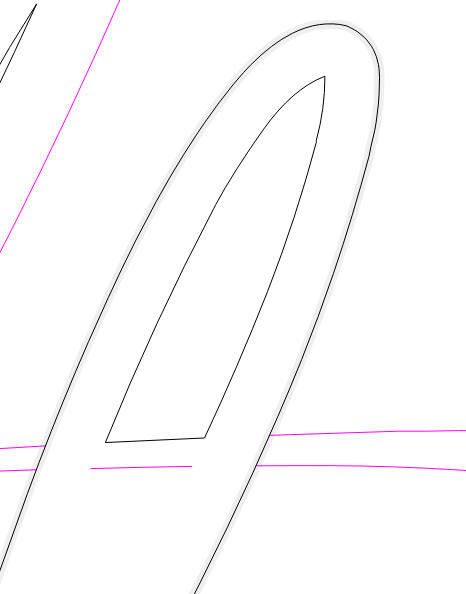
- Zoom in, see that the lower divider line doesn’t touch the interior vector. Select the lower line, use ‘Node Edit’, and drag the left most node so it cross over the vector:
- Select the interior vector and one of the two lines, use ‘Trim Vector’, then select the part of the interior you DON’T want to get rid of it.
- You still have two unclosed vectors at this point. You can EITHER
- Delete the horizontal line, select the vector, and use ‘Join Vector’
- OR, selectboth parts, use ‘Node Edit’, and move the end nodes of the horizontal line to match the end nodes of the vector, then ‘Join Vector’ with both selected.
Either one works because you just want a line. If the ‘horizontal line’ wasn’t a straight line, use the second method to preserve it as part of the vector.
Now drag the copy of the interior vector back into place, and repeat for the other line.
TheSign.c2d (239.3 KB)
And with the other vectors of the ‘T’ closed and joined up with the letter ‘h’:
TheSign.c2d (259.8 KB)