Not much of a difference with 91 degrees specified, however for some reason it looks passable from the top down photo this time? maybe just because the lighting is a little more diffuse.


1 Like
How about your Z steps/mm calibration? The corners rely on 3 axis motion. If your Z is lagging behind, you might see something like that.
3 Likes
That’s a great suggestion - I didn’t know that was even possible… I found this in the docs, and will attempt it with my cheap set of plastic dial calipers (it’s the best I’ve got).
Something tells me @neilferreri nailed it (as usual), so I’m looking forward to the results. I checked my setup and realized that while my X and Y are calibrated, my Z isn’t anymore (I messed with my GRBL settings a lot recently and may have forgotten to reset it), so who knows, I might be off by a little bit too.
I think your z belt may be too loose. After you set Z zero with the paper test, try jogging up a few inches and then back down to zero. Does the paper still feel the same? I had a bit of slop in my z axis which I discovered with a dial indicator, but you might be able to approximate that with the paper test.
-Dan
3 Likes
Is the tip of your V-bit come to a point? There are some made that have a flat tip…
1 Like
Yeah, it’s a pretty fine point on this one (you can see it in the bottom of the flat-depth pieces). On the initial project where I ran into this problem, I was using a different 60 degree v-bit that I discovered had a much larger flat point due to bad design (or they skipped a sharpening step?) and I thought that was the issue, however it has persisted with a much finer point v-bit.
I’m working on that this morning. It seemed tight enough, but this morning I’m re-tightening it, checking Z carriage v-groove wheels, and then running calibration. We’ll see how it turns out.
1 Like
The flat tip usually just causes individuals to set their zero too low, but you can still get a good carve when that’s taken into account. You’ll usually see bulging edges and rounded corners when the cut is too deep.
1 Like
So, I tightened up the Z-belt a bit, re-adjusted eccentric nuts on the Z carriage, and then ran a calibration.
My measurements probably aren’t super accurate since I just have a cheap plastic dial caliper. I tried a few ways of mounting it, but ended up just making marks on the extrusions and measuring them afterwards. I zero’d it out all the way up - then moved 90mm down. it was nearly a whole mm off, about 90.9 - so I used one of the calculation spreadsheets floating around and adjusted $102 - then ran the same test we’ve been using.
Was really hoping for a big difference, but I didn’t see much of one upon close inspection. A is the first time we ran this test - B is after Z calibration.


I probably need to calibrate X/Y as well, but not sure if it will help.
1 Like
@cbbo Did you try entering the angle as 88 or 89?
1 Like
I had not tried that yet - we went larger (91 degree) but didn’t go smaller. Here they are:
89 Degree:


88 Degree (sorry, the cut ran into a previous test cut I did on this piece of scrap)


Better? Hard to tell. Maybe 85 or 80? Just to see if something changes.
What bit (manufacturer, part #) are you using? Have you tried a different one?
I didn’t notice much of a difference at 88 or 89, but it’s definitely not any worse. I thought maybe I saw a little curve at first glance, but it’s not as noticeable in the pictures.
I already ran a triangle test at 85, 90, and 95 - and got the expected results… the weird corner problem persisted through all degrees. I can try it with these shapes though, willing to try anything at this point.
I’ve mostly been using a Whiteside 1550 (60 deg 1/2 inch), I’ve measured it and it seemed damn close to 60. I have tried 60 and 90 degree half inch Freud bits as well… (the Freud 60 is the one with the wide tip issue).
Just throwing this out there, but I doubt it is the cause…
Could it be a accel/decel issue? I had an old laser that would have wobbly lines in corners until I slowed the accel/decel parameters.
Like I said, I doubt this is it, but maybe worth a try?
4 Likes
I think your problem is a combination of:
- Your cutter angle not being correct, and then
- The physical impossibility of perfectly cutting a wall of specified angle with a wrong cutter, no matter how much you try to correct in software (at least with V-carving).
Part 1: my thoughts about your cutter angle not being right. I grabbed a copy of CAMotics to simulate your gcode with stock removal instead of tool movement lines in space. Let’s see how it looks with a perfect 90 degree cutter:
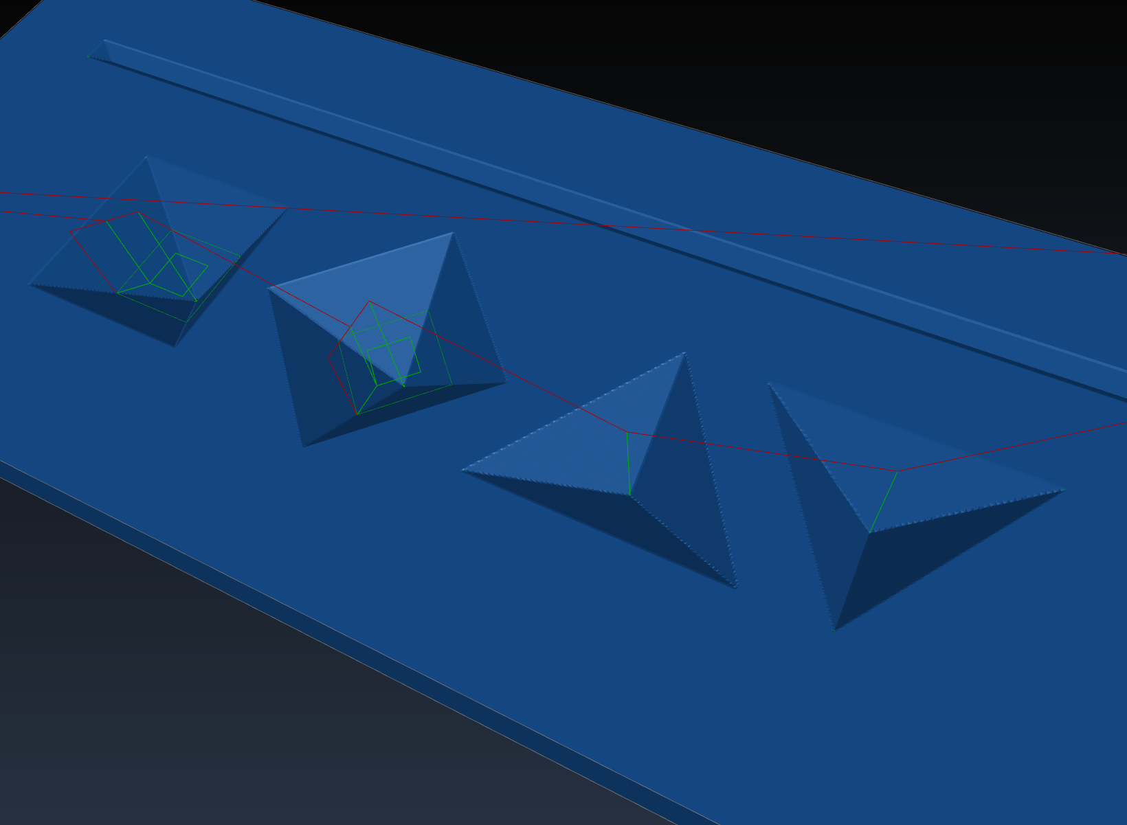
(Looks good to me.)
Next, for illustration’s sake, let’s run the same program, but with a drastically wrongly-cut cutter (60 degrees actual, vs expected 90 degrees):
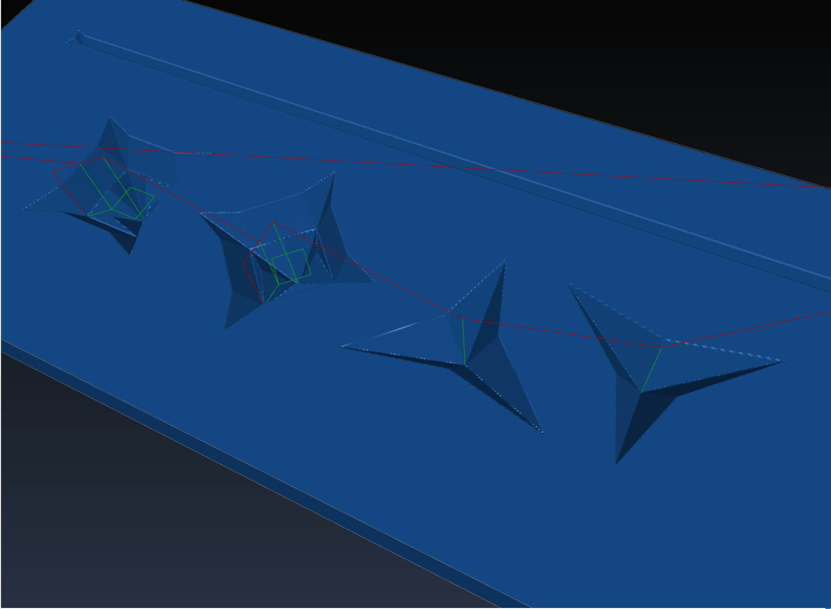
See that? The same flavors of geometric aberrations as we’re seeing in the physical examples. I think your cutter is less drastically wrong - 89 degrees, or something like that.
Part two - I don’t think you can perfectly correct in software for a wrongly-made cutter, at least using a V-carve pathway (hence why your adjustments don’t work). It’s a physical impossibility with angles. This part requires more of a mental exercise, because I can’t illustrate it with software, the way I can above.
Basically, let’s say you have a hilariously undercut cutter that’s maybe 5 degrees, instead of 90, and essentially looks like a needle. Without a 4th axis, and using only the movements that you’ve seen V-carve put out, is it even possible to cut nice 45 degree walls? I don’t think you can. No v-carve strategy can accomplish this. You end up doing a central plunge, maybe doing a lap near the bottom, then trying to run the tip up the corners at a 45 degree angle, but you’ll never clean up the walls between. You need to move to something like a stepover milling strategy (indeed, a 0 degree cutter is an endmill), which is kind of the antithesis of the V-carve technique.
I don’t think it’s possible to generate a v-carve pathway that perfectly produces your desired result, with your current v-carve bit. You can kind of fudge it, but the cost is the aberrations you’re seeing.
Sorry. I’d be happy to be proven wrong.
(Edit: a more concrete example of point two: holding a sharpened pencil perfectly upright, can you make a perfect inverted pyramid in clay with v-carve techniques? I can’t. The best I can do looks like the examples above.)
Edit again: I think there’s a philosophical/intent question here, too. The purpose of V-carving is to achieve a cut of a certain width at the surface, without having to do multiple passes (depth and everything else be damned). If you need it wider, you go deeper. Sometimes we can abuse this to get nice mathematically and mechanically clean results, but that’s the exception and not the rule. This thread is the rule.
For sake of completeness, a 95 degree cutter (problems become very apparent very quickly with overangle cutters - probably why we see so many underangle ones):

4 Likes
I agree with number one, but I don’t think number two really matters here. Regardless of the carve angle, a square should be square (hope that came out right).
1 Like
“Square”, the 2D shape, or inverted truncated rectangular pyramidal with specified wall angle?
As long as the wall angles in software match the true angle of your cutter, you’re gucci. Violate that and you’re gonna have a bad time. (Cf. this entire thread).
2 Likes
Square.
The original file was done in V-carve. I can’t open the file, but I’m assuming (I know the saying) that the
was drawn as a square. I get what you’re saying about an 88° v-bit not being capable of a carve angle of 45°, but I think the OP is looking for a perfect square at the surface. If this started as a 3D model with defined wall angles, you’re correct that the software can’t compensate for the end mill’s angle being off.
1 Like
Yes, it’s just a simple square vector. I also am doubtful it’s an issue with the angle of the bit - not only have I measured them with a protractor (they all looked perfect) but I’ve run various cuts specifying different angles and the problem in the corners didn’t seem to be affected - but the problem shown in Bob’s image does become apparent the further from the true angle I get, which is expected. I don’t get curved sides when specifying the true angle, instead I get straight sides that have an outside offset at each corner, and that offset matches the width of the bit as it makes the clearing cut up to define the corner.
And you are correct, my goal here is just to get an actual square at the surface. I’ve tried 3 different v bits so far, and it’s happening with all of them. I recently acquired 1/4" 60 and 90 degree whiteside bits, so I may try those this weekend…
Alright - hopefully this demonstrates things well - test run with a brand new 90 degree quarter inch v-bit.
The corner cut offsets are more apparent because of the smaller tool diameter. With a half inch v bit it was difficult to cut full depth shapes big enough to show the issue - as the bit diameter was nearly half the full width of any single side.
Now with the smaller diameter bit, you can clearly see that the clearing corner cut is the only one that is offset, in both the full depth and flat depth toolpaths.


1 Like