Problems with v-bit corners

Hello folks… first-post here! Relatively new to CNC but I’ve figured most everything out, until now.

I’m having an issue that only seems to manifest with v-carving of corners… It occurs in full depth v-carving, or with a flat-depth set (Using Vectric Pro). Seems to happen irrespective of feedrate, depth of cut, or stepover values, or the degree of vbit I use. Essentially any “inside” corner that I cut seems to be offset a bit, and never matches up with the rest of the bevel edge. I noticed it first trying to carve a sign with a vector that was being beveled out with a v-carve path to a flat-depth, but I’ve since boiled it down to simple shapes to try and identify the culprit.

I’m running a Shapeoko 3 XXL with the Carbide Compact router. Using Carbide Motion 4. The images below are from tests I ran on MDF.

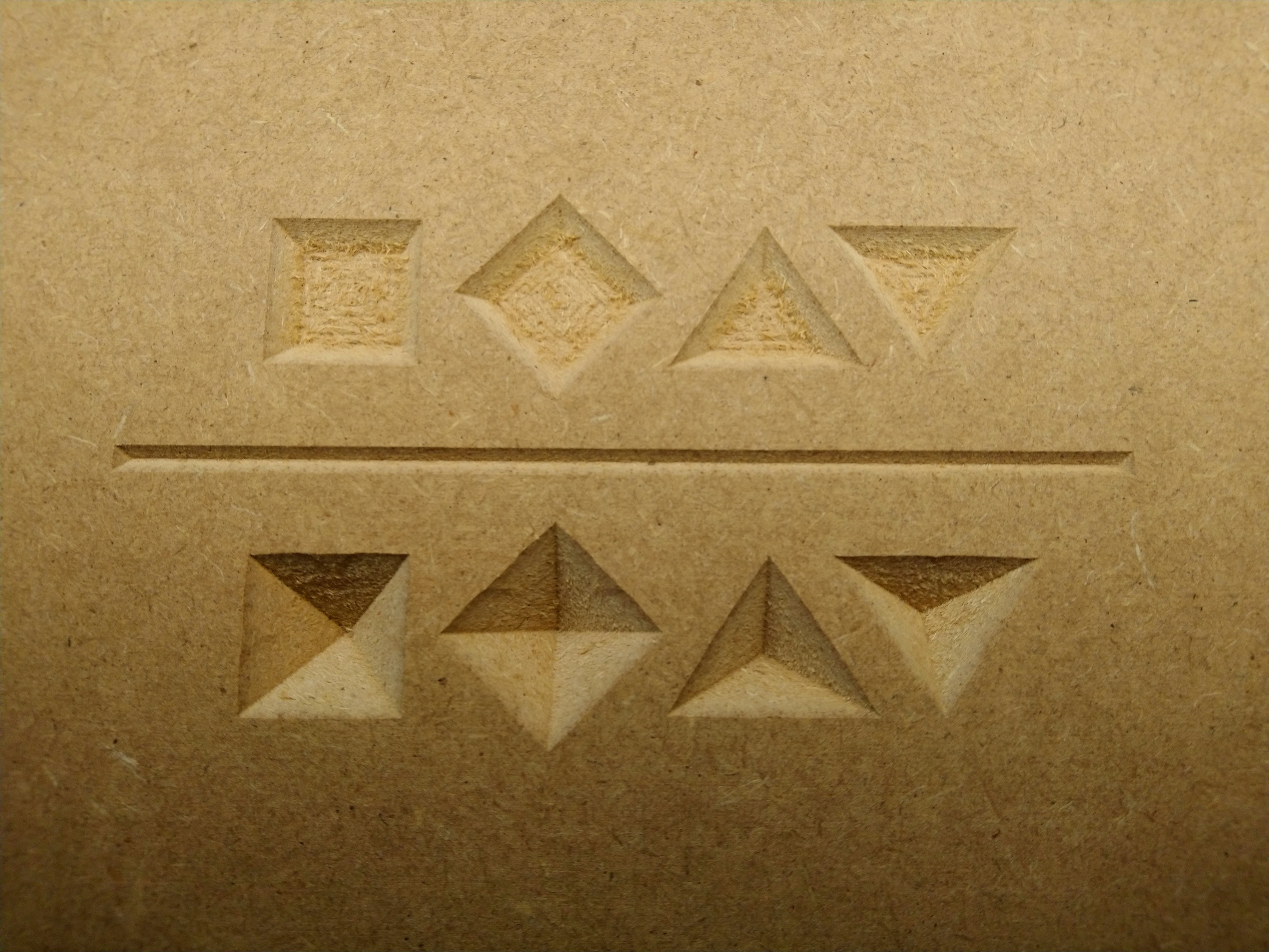
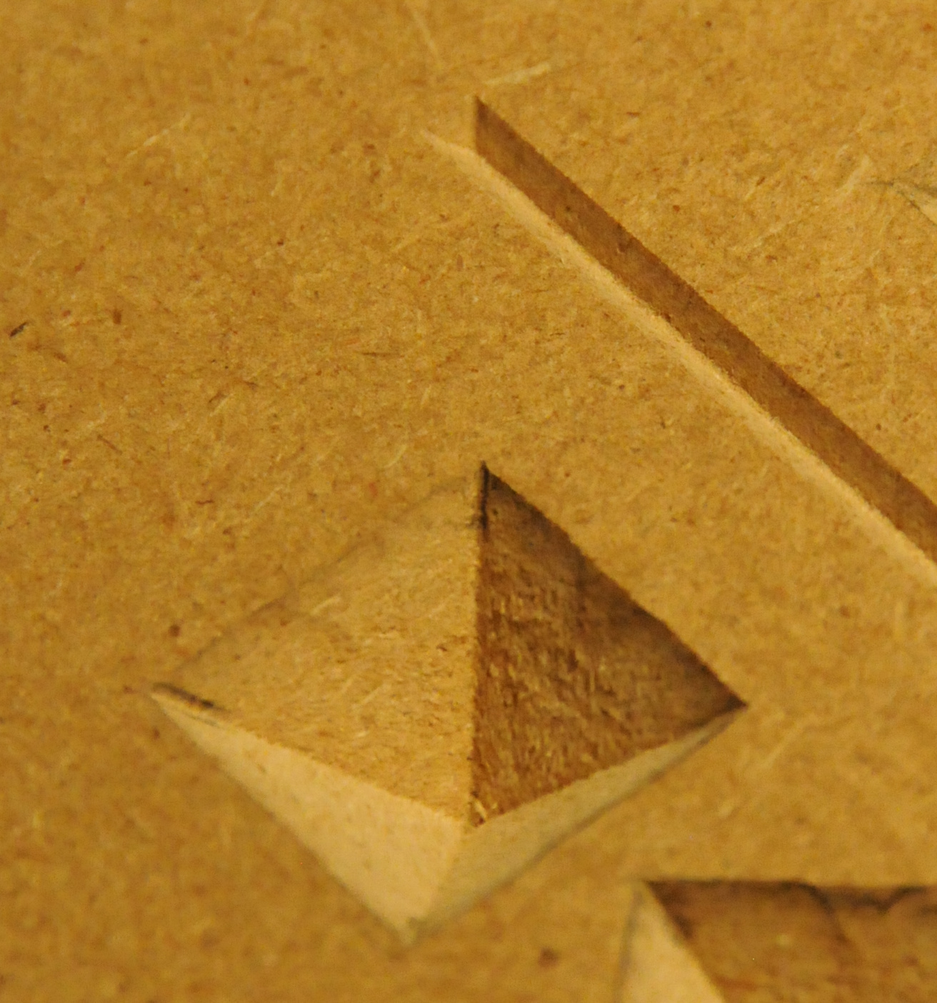
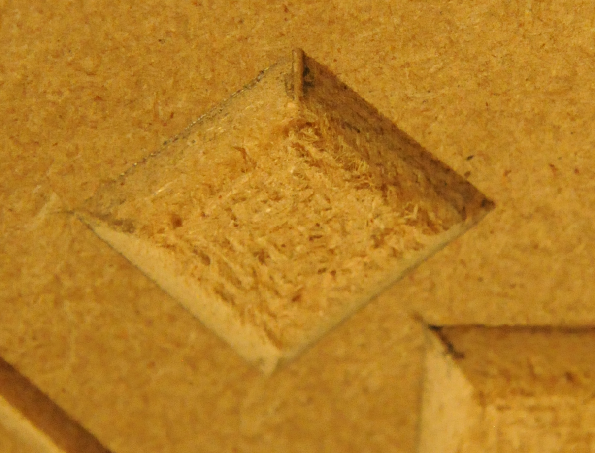
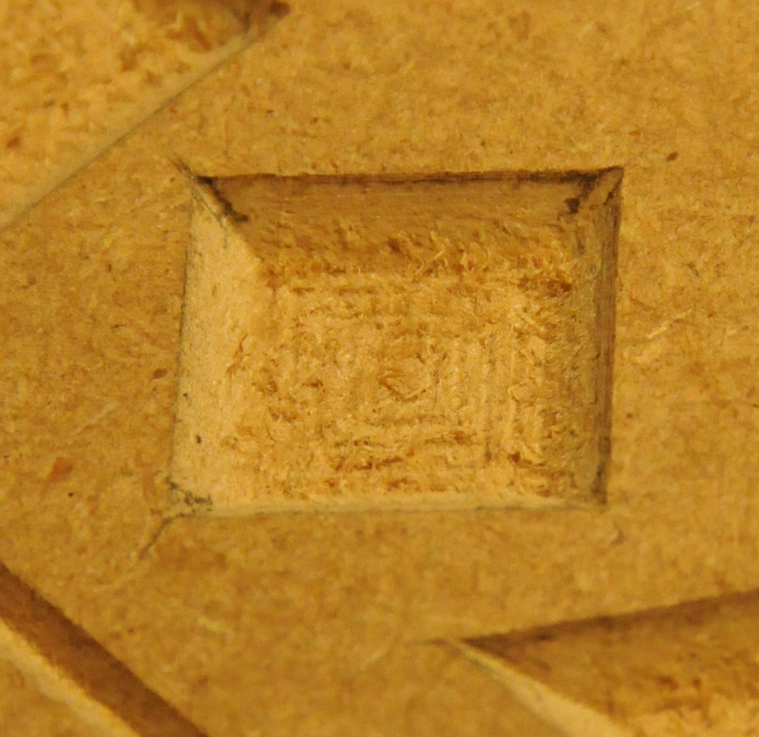
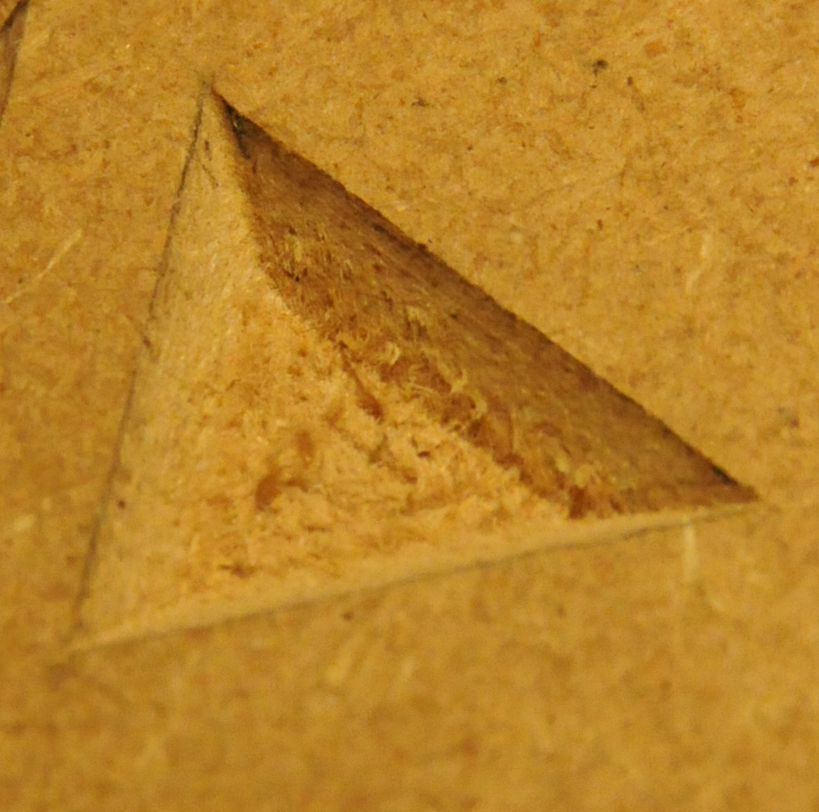
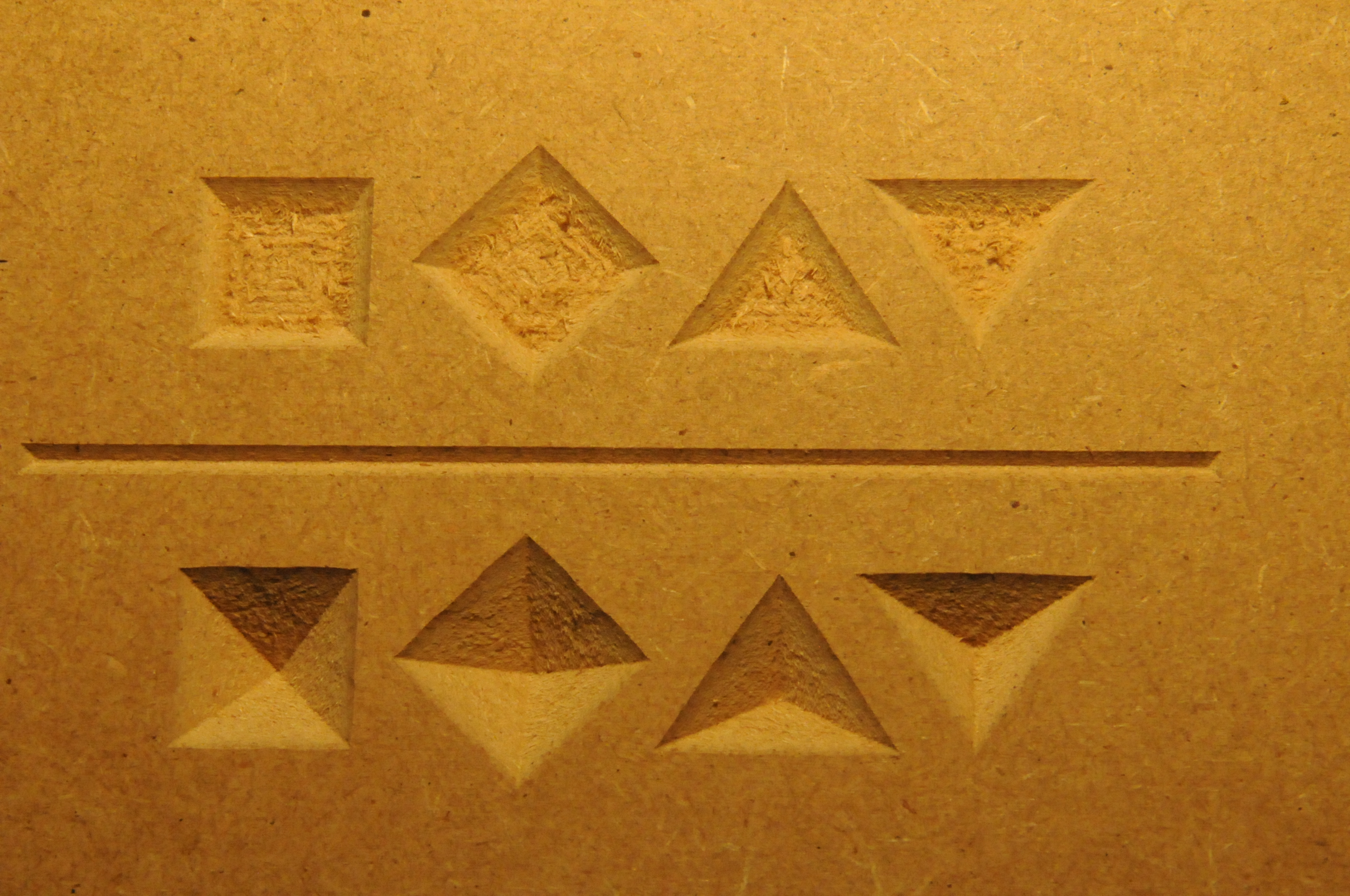
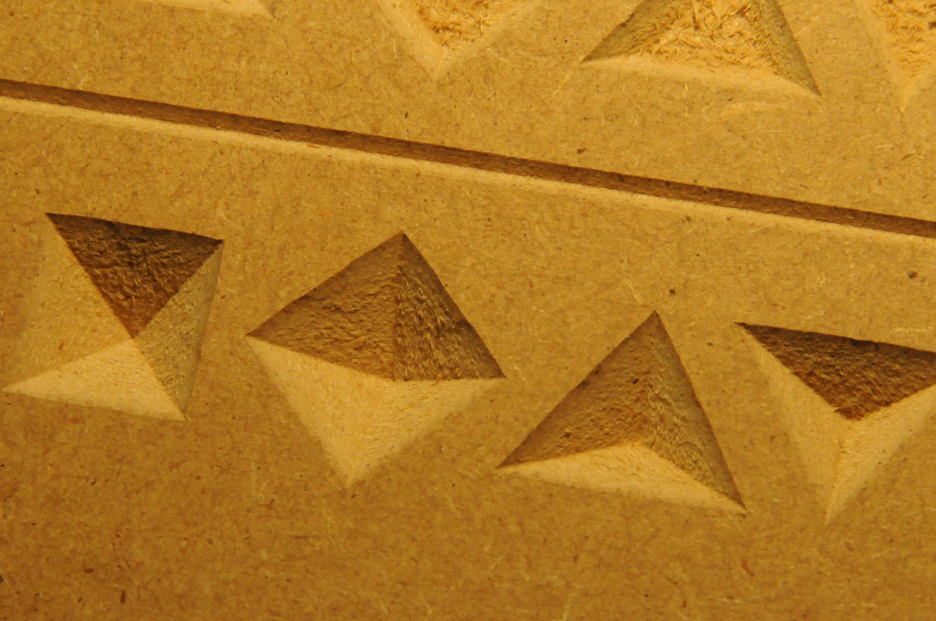
This is an example of what happens in corners when cut at full depth, I was just using triangles as test shapes.

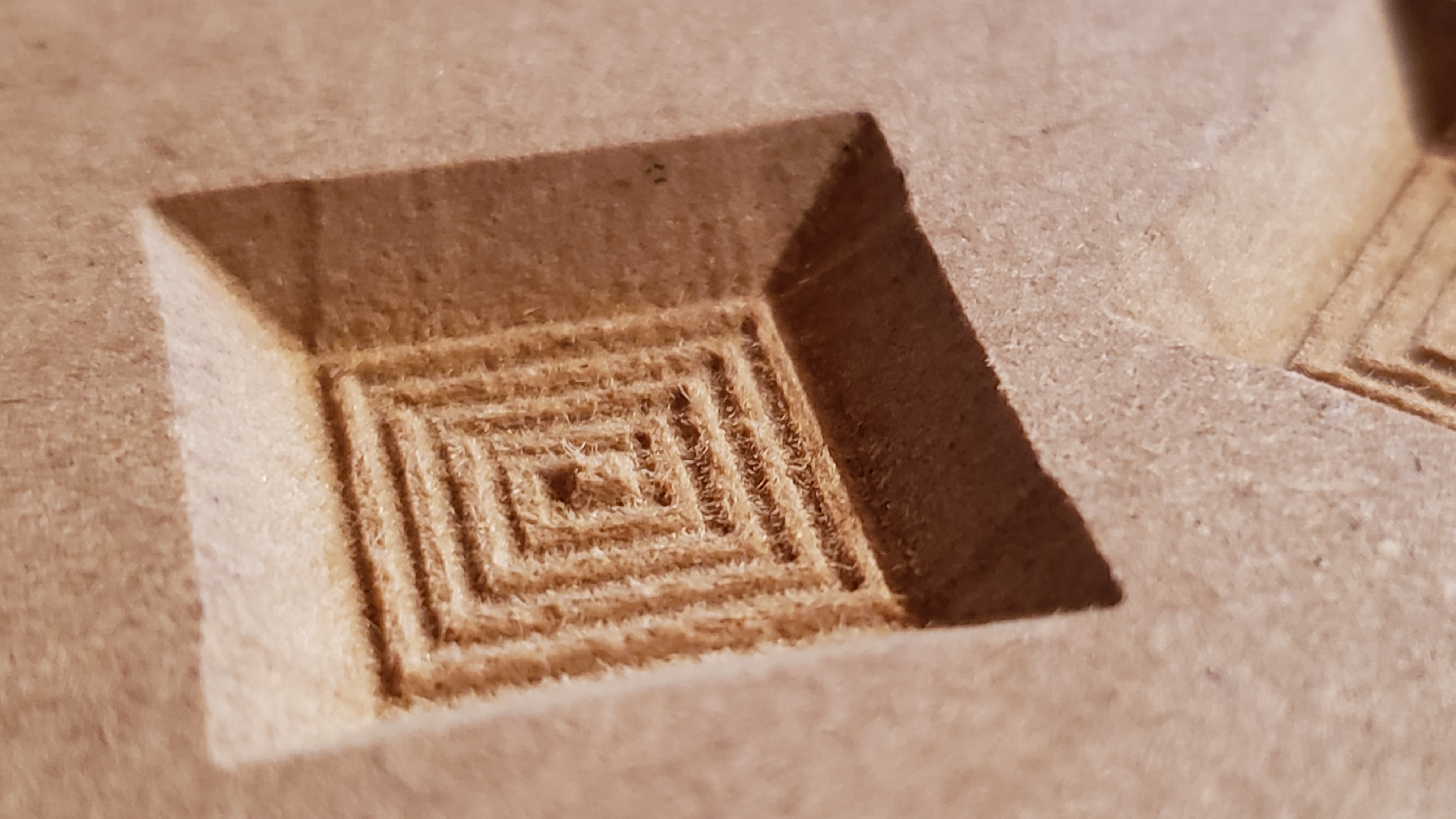
This is what a full depth situation brings - the squares are 3/4 inch width and length, but where the toolpath comes up to finish the corners, it’s .05" wider across. The center of each edge, where it leaves some material, is the proper .75" in size.

I’ve gone over this problem over at the Vectric forums - trying to understand if this is some software issue (I really think not, at this point) or a machine/controller problem. I’ve ran the degree tests, measured my bit, made sure my machine is square, material and wasteboard are flat, etc… I re-read some troubleshooting threads and guides - and today I discovered on eccentric nut on the left Y carriage was slightly loose, so I tightened that up… and realized during assembly I had probably over-tightened some of the other eccentric nuts, so I got everything fixed up.

However, the problem persists and hasn’t changed at all. Any suggestions?
I’ve even opened up the gcode in a third-party viewer to verify everything looks like it should.

1 Like

Another image that I thought I had posted first - a flat depth cut with the simulation for comparison. Highlighted the offending part of the toolpath and the cut…

1 Like

It seems like you have thoroughly covered a lot of your bases already (kudos for that), but here are a few random thoughts, brainstorming style:

  • which “degrees test” did you run and what was the outcome ? does the problem get better of worse if you artificially modify the V angle value in VCarve slightly, e.g. declare the 60°V bit as being 59° or 61°
  • how do you set your Z zero, and does this still happen if you artificially set it a tiny bit higher
  • does this happen irrespective of where the cut happens in the work area ? (i.e. if you cut that 3/4" square at various positions across the wasteboard area, does it come out looking identical)
  • you did not mention double-checking your Z-belt tension (unless it’s in the “etc…” part), or even the X/Y belts for that mattter ?
  • if you jog the Vbit close to the surface and try to wiggle it with your hand, does it show any sign of play along any axis? The V-wheels/eccentrics might be perfect and yet something the X/Z plate or belts might be a little loose, it does not take much.
  • did you try slower plunge rates?
  • what depth per pass do you use ?
  • if you V-carve a single V slot (i.e. draw a line, create a profile toolpath, set a small enough depth of cut that it cuts the slot in one pass), does the problem occur ? (i.e. does the problem occur when the tool does not have to retract and plunge again)
5 Likes

It’s worth watching https://youtu.be/3Kw7bfC8VRo or at least the second half of that… it’s discussing something very similar including a solution at https://www.cncnutz.com/2017/06/test-your-v-bit-angle-episode-151.html

2 Likes

Usually the best thing to do here is to leave a roughing clearance (larger than the divot) and make a finishing pass.

(assuming the machine is mechanically sound)

One thing which may help is to enable G2/G3 arc generation in the post-processor — for some reason it is turned off in the official posts for our machines.

1 Like

Thanks for the suggestions - I’ll try to cover everything:

The degree test was similar to what fenrus posted in the video - triangles with different angles specified - I actually only did a 55, 60, and 65 cut - and because I wasn’t seeing any curve in the 60, I didn’t bother doing more granular test, however that might be prudent since I’ve not had any better ideas so far. In some of my pictures it may seem like the triangle has a curve, but I think it’s just an optical illusion because of the lighting… I double checked everything with a straight edge.

I typically set Z zero using the paper method, sometimes a little higher, sometimes a little lower - but I also have the Carbide branded probe and have touched off of that. The only difference I’ve noticed is if I’m a little low, the corners aren’t as crisp - but the larger corner issue persists.

Correct, position on the material hasn’t had an effect, however I haven’t tested specifically for that. Most tests I did were varying some other detail over the same shape - but the issue persisted.

I did tighten up my X and Y belts, but left the Z belt alone as tension felt OK to me.

I’ve not felt any play in the spindle or bit when it’s down near the surface. I was pretty amazed at the precision I was getting after assembling this thing, being new to CNC and all. I thought I had fully dodged a bullet until I ran into this issue! During assembly I used the Loctite where suggested, and I’ve gone back over to make sure everything is still tight - but will double check.

Just about every time I adjusted my Feed rates, I adjusted plunge rates to the same ratio. Went all the way down to about 9 IPM FR and 2 IPM PR in some of my tests.

I ran a 4x4 matrix of full-depth vcarve triangles using .25" to .1" depth per pass, with Clearance Pass Stepovers from .14" to .04". Clearance Pass Stepover is used by V-Carve Pro as the stepover when the v-bit rough clears at mulitple z-levels… EDIT: in the pic below I used pencil led rub to hopefully show the issue more clearly.

I will have to run the single line profile toolpath to test, but I believe that may have been covered in the first project I ever attempted, and I didn’t notice it then… Will follow up on that.

2 Likes

Wow that is one thorough answer. Until I (or someone else) can think of a good way to determine what’s going on, to triple check that the problem is not in the toolpath itself, I’m willing to run your test cuts in MDF on my machine over the week-end. I have a 60deg and 90deg Vbits (from Carbide3D) and VCarve Desktop, not sure whether a VCarve Pro project opens correctly in VCarve or not. Or just send me some G-code(e.g. of that 4x4 pattern) and I’ll run it, I’m crazy enough to run someone else’s g-code :slight_smile: (well after I have checked it in a visualizer that is)

2 Likes

You certainly covered many bases in your process. Something you do not mention is the router speed you are using. Your feed rate is dependent on your router speed. If you feed at a rate that is not appropriate for the router speed, it is possible that the bit gets deviated in the material. Is your bit seated all the way in the collet? you could also have bit deflection.

While it is often discussed here, one thing we have not determined very clearly in this forum is the optimal F&S for V bits on the Shapeoko.

2 Likes

Hah, yeah I had already done that matrix a few days ago, when it was suggested on the Vectric forum that deflection/flex due to pass depth or stepover may be causing the issue. And I really try to do my own research and homework before pestering people on forums :slight_smile:

I don’t recall exactly what RPMs I used with each feedrate, but I’m confident it was always between 2 or 3 on the Carbide Compact, which is somewhere around 14k-18k? I don’t think I changed it much.

I’ll whip up a new V-Carve project with some of the triangles and squares, run the test myself and document my RPM, and share the project file and gcode to compare!

Thanks for all the help!

3 Likes

Here is the project on Google Drive - I’ve included the .crv file and a summary job sheet, plus the generated gcode, via the Shapeoko (MM) post-processor.

I drew some shapes, and a skinny v-carve rectangle - plus a repeat of the shapes with a flat-depth set. I adjusted the final clearing pass on the flat-depth toolpath a little larger to speed things up (since we don’t care about finished surfaces on the bottom of the shapes). It’s set up for a 90 degree .5" vee bit. The toolpath calls for 16k RPM, I will try to get as close to that as possible (should be 2.5 on my Carbide Compact router), however I’m not sure how appropriate that RPM is.

The MDF scraps I’ve been using are roughly 8x9 inches, 3/4 deep so that is material size in the project file - but this takes up only about a 6" wide by 4" high section from material origin, which is bottom left.

Hopefully this is good enough to demonstrate the issue and can give us a decent comparison between the cuts each of our machines makes.

1 Like

Uploaded some pictures of the result into the Google Drive folder. I can see the issue in every shape. Even in the corner of the tiny stripe where it doesn’t retract or do multiple passes… A little harder to see in the flash pictures - hit some of the edges with pencil led to help them stand out.

At least it’s consistent? :joy:

Here’s a first pic of my run (I used the gcode as is, I confirmed that VCarve desktop can’t open VCarve Pro files, or at least not v10 files)

I’ll take more shots/close-ups and post them soon

Video of the cut (just because)

2 Likes

I did the pencil thing (poorly) and took a few close-up shots


There are hints of the issue in the squares, but not to the same extent

2 Likes

Hmm… Yeah not as exaggerated as mine…

At least it’s not just me, entirely! I’m still very puzzled, however.

I made a video as well. I noticed some table shake this time, need to brace my table better… my goodness I hope it’s not something as simple as that.

Should we repeat the test with a lower pass depth ? say 0.1"

Sure. Thanks so much for helping test! New gcode in the folder with .1" pass depth. Same placement, so I’ll simply adjust Y zero, I think I have room on my material. Starting to run out of scraps to cut, haha.

With 0.1" per pass:

The following pics do not show it very clearly, but visually the top shapes look near-perfect to me, the bottom triangles also, while the two bottom diamonds still show a very slight sign of the problem, maybe a bit less than in the 0.25" depth per pass test.

Maybe the full depth triangles look a little better in mine this time? only a tiny bump… Otherwise, everything else looks nearly the same as last run to me. Put them on imgr this time, can’t seem to get direct link to the drive photos.

That pic:

makes me think it’s not mechanical, it’s so even and sharp in all four corners. Maybe let’s do the “declare the bit as being 61 degrees” test ?

91 you mean? Sure! updating files now.

1 Like