Program zero in CC and Meshcam

I’m cutting out several filleted discs out of brass stock for which I made a jig in the waste board of my Nomad 3.

In CC, I have the bottom left set as zero.

Now in Meshcam, how do I move the part zero to the exact position of my jig?

Thanks in advance!
Gunter

Hey Gunter!

I don’t know the answer…

… but as an alternative, have you considered sticking with 2.5D in CC (or similar) and using a corner rounding endmill (like this) to quickly get your filet edge?

Hey Gerry, thank you for replying.

My understanding is that CC can’t handle these fillets… am I wrong?

Having said that, I’d like to learn meshcam for 3d cutting. So far, I’ve found a few tutorials
but none of them seem to cover this issue.

Many thanks,
Gunter

I don’t see why not. It’s a simple planer toolpath. Create a tool the tip diameter of the corner round bit, and set your depth to the radius size. (I usually fudge it a bit and make the tool just a hair bigger (0.005 / 0.1mm), and the cut depth just a hair smaller to avoid the corners of the bit from leaving a line.)
It won’t show the rounded corner in simulation, but the path will be right.

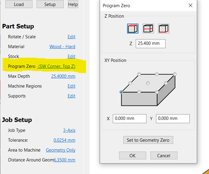
As for setting your zero… How will you pick up your zero point of the fixture on the machine. Set it to the same location in Meshcam. It really doesn’t matter what the zero was in CC to make the fixture. As long as Meshcam & the point you pickup on the fixture match.

Are you using roundover bits?

See:

As Todd-less-1-d implies, the tool support for the preview doesn’t really matter.

If you draw a circle in CC then the endmill moves in a circle.

If you put a ball endmill in you get a groove. A V-bit a V. A flat endmill a slot. An a corner rounding endmill, a fillet.

The Gcode is the same and the machine has no idea what you are cutting with.

Just click on the text adjacent to Program Zero - another box pops up and you modify the co-ordinates as required:

1 Like

@3DGG Thanks for your suggestion… I tried that but it moves the xyz coordinates correctly, not the stock itself:

Can’t seem to get to move the stock to the xyz coordinate position.

Thanks,
Gunter

10 pc domed discs.mcf (1.7 MB)

Will, I’m using a 2mm ball end end mill.
Thanks,
Gunter

Is your workpiece (stock size) dimensions the same as your jig?

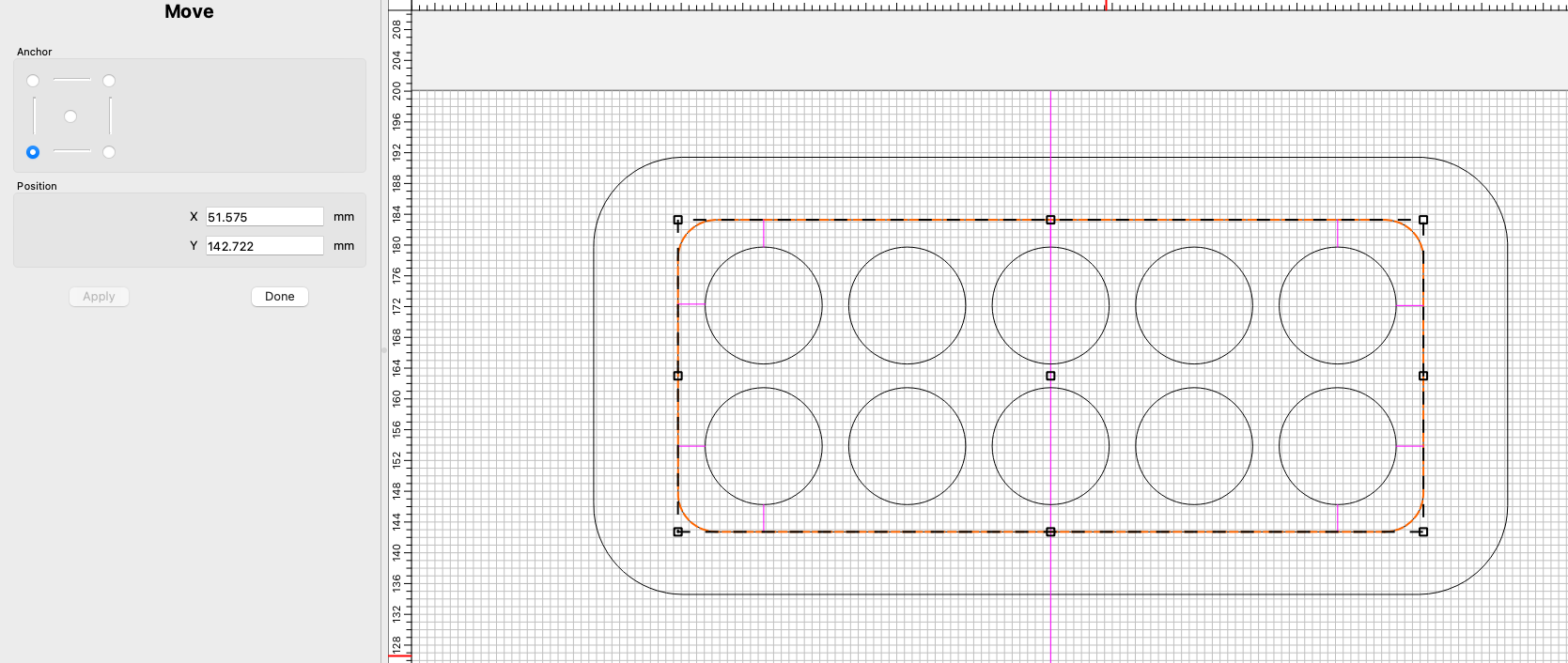
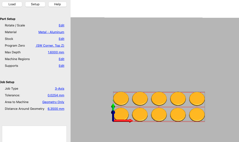
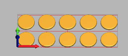
From your pics - it looks like the workpiece is bounded by the tangent edges of your disks:
image

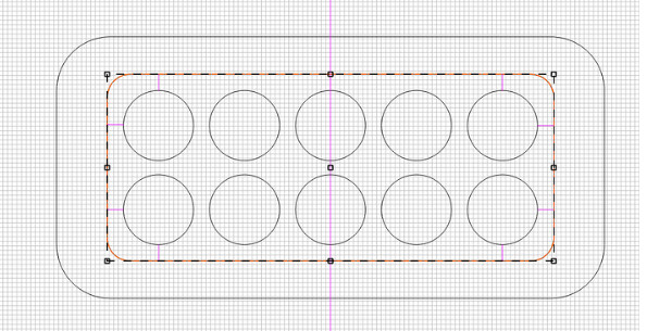
But your jig hole (for lack of a better term) is bigger:
image

I would make them the same - and use a common point for your zero. Likely I’d just modify the dimensions of the workpiece so it is exactly the same as your jig hole - by adding XX mm around the periphery.

Or your could try to use the exact center as your zero - and make sure everything is zeroed like that. But I’m a lower left guy myself and if I were to change it up, my chances of screwing something up increase substantially.

1 Like

This topic was automatically closed after 30 days. New replies are no longer allowed.