as requested on support…
First, measure your stock:

Then set up the Job as described in:
https://carbide3d.com/hub/courses/create/job-setup/
Launch Carbide Create:
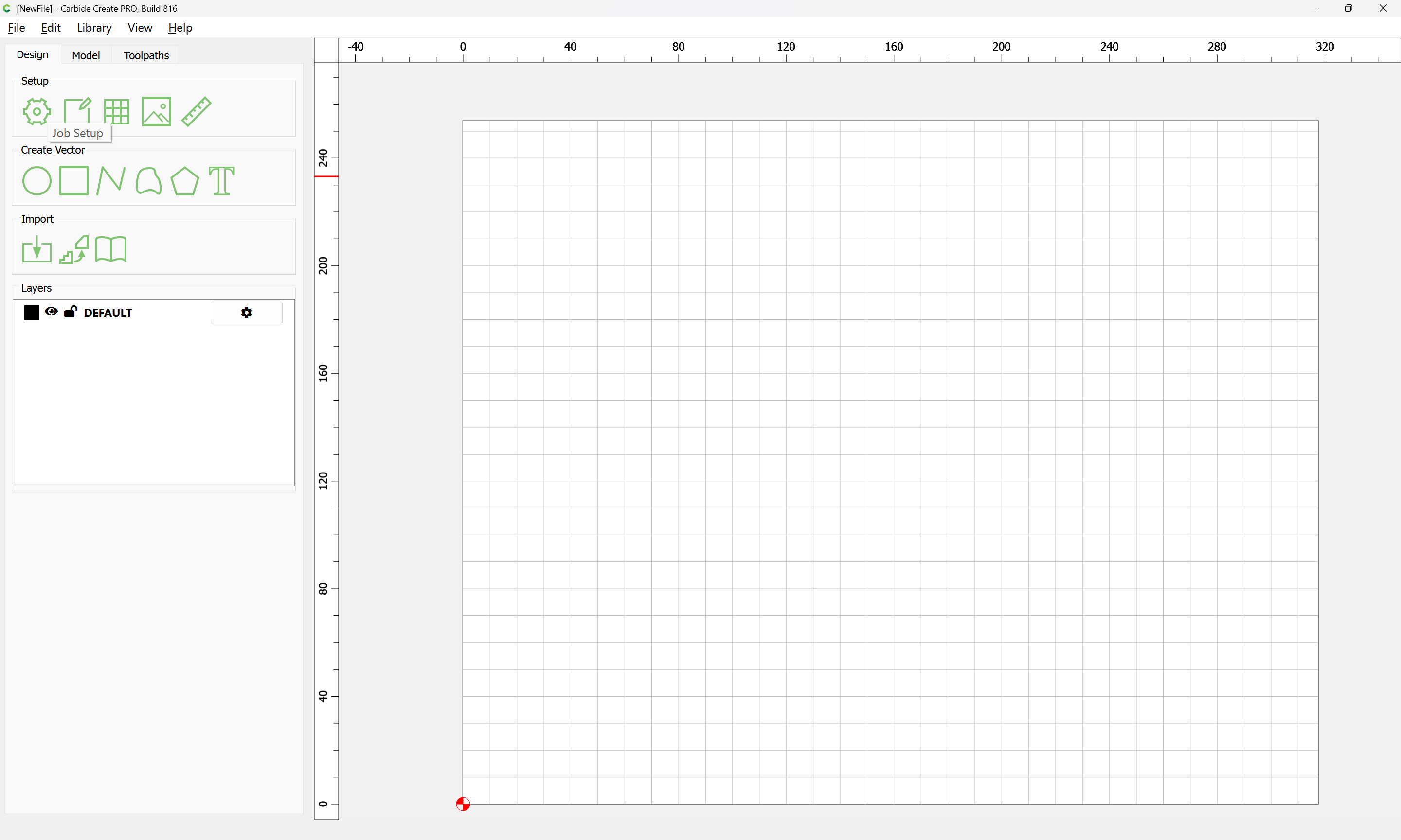
click on “Job Setup”
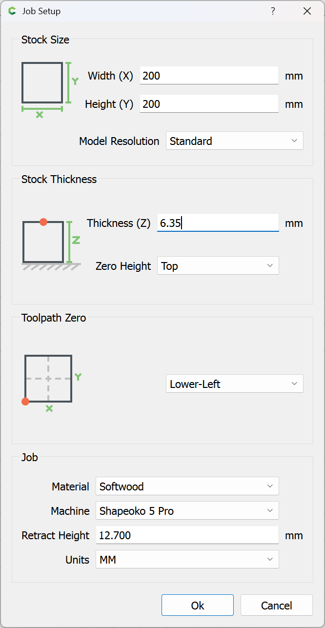
and fill in the desired parameters.
as requested on support…
First, measure your stock:
Then set up the Job as described in:
https://carbide3d.com/hub/courses/create/job-setup/
Launch Carbide Create:
click on “Job Setup”
and fill in the desired parameters.
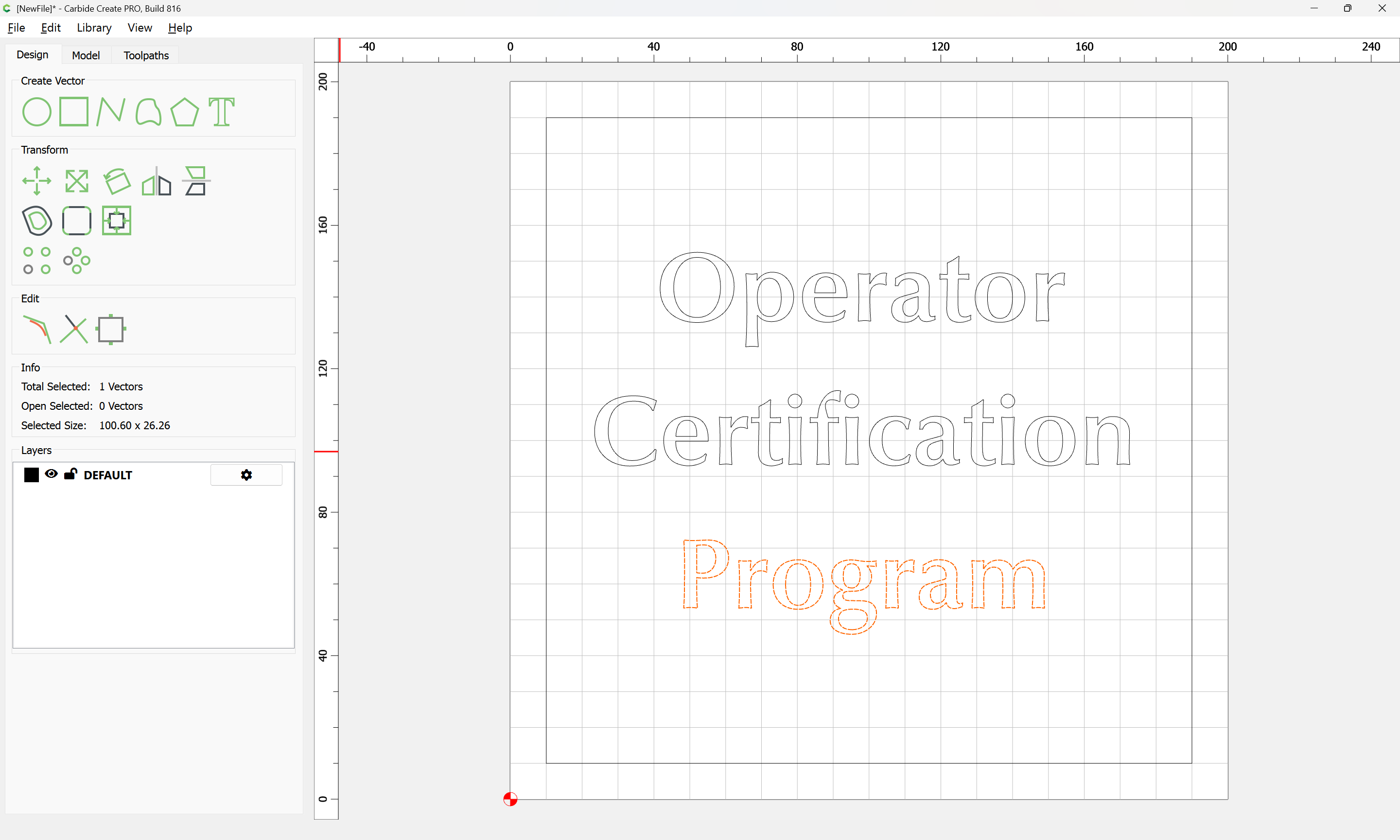
Then, create the design in the Stock area using the drawing tools:
See:
https://carbide3d.com/hub/courses/create/shapes/
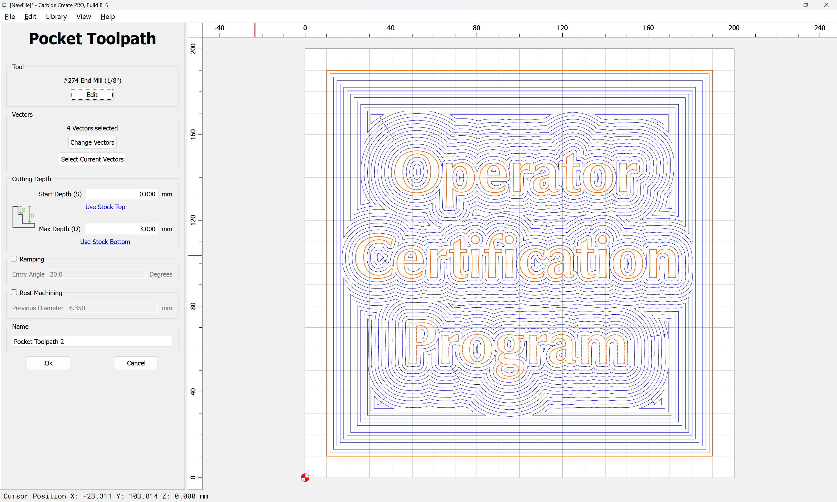
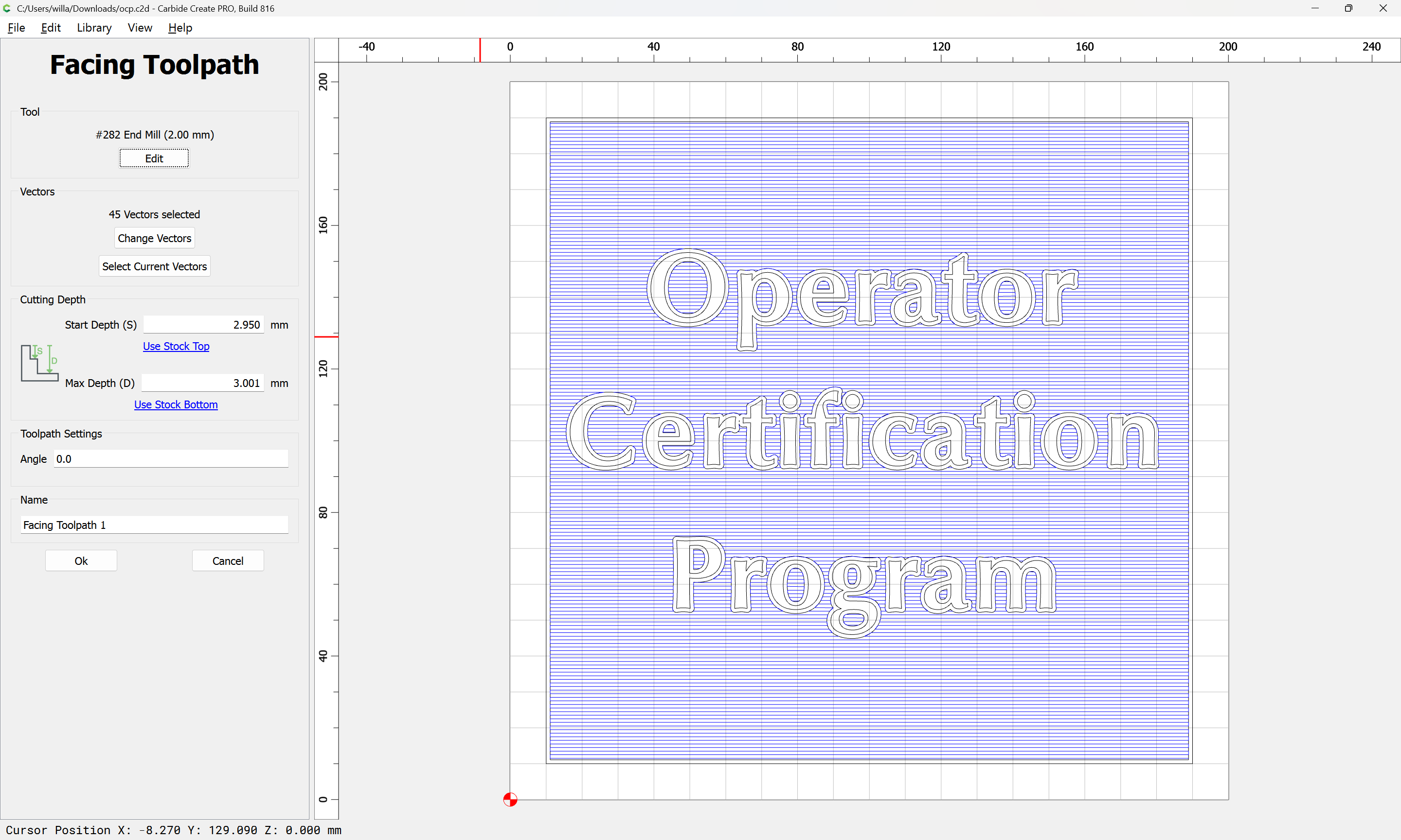
Then assign suitable toolpaths using appropriate tooling:
For a discussion of toolpaths see:
https://carbide3d.com/hub/courses/create/toolpaths/
and for tooling and feeds and speeds see:
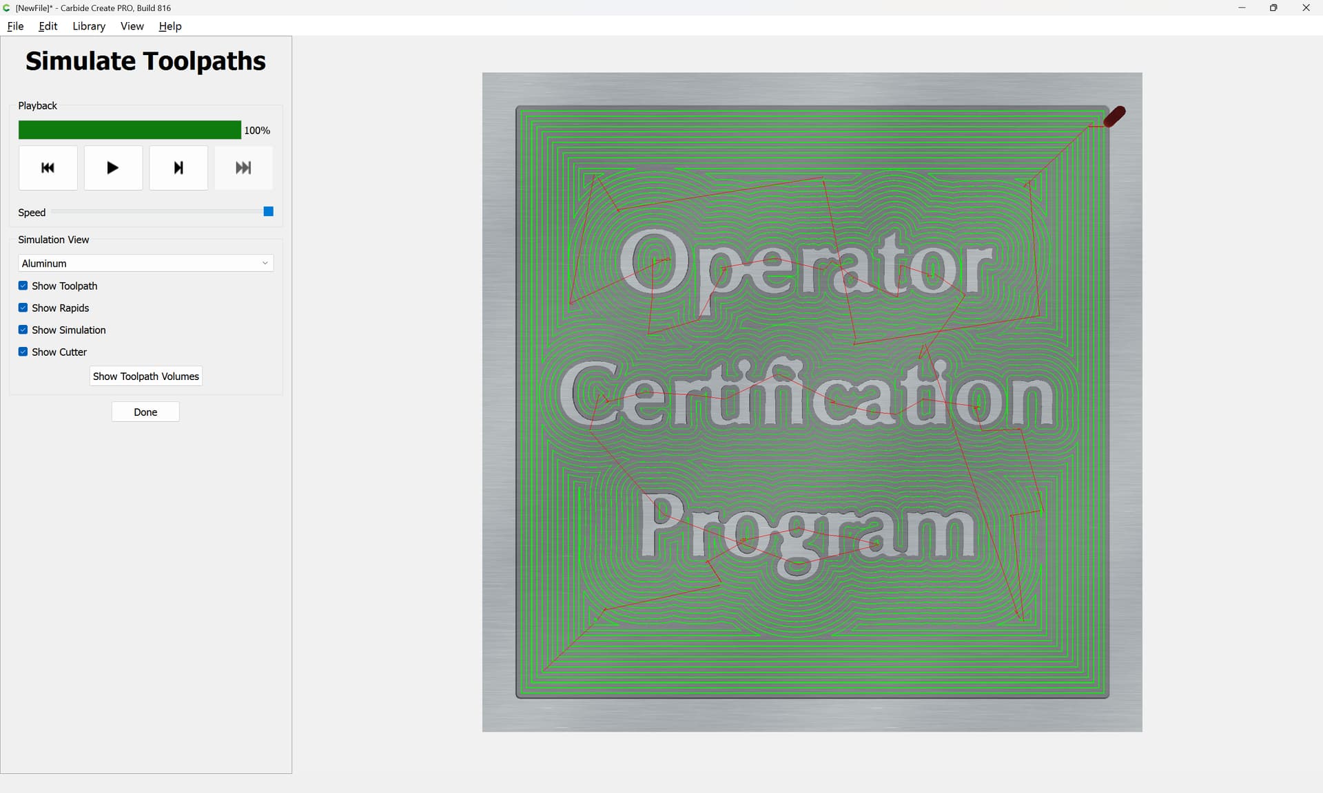
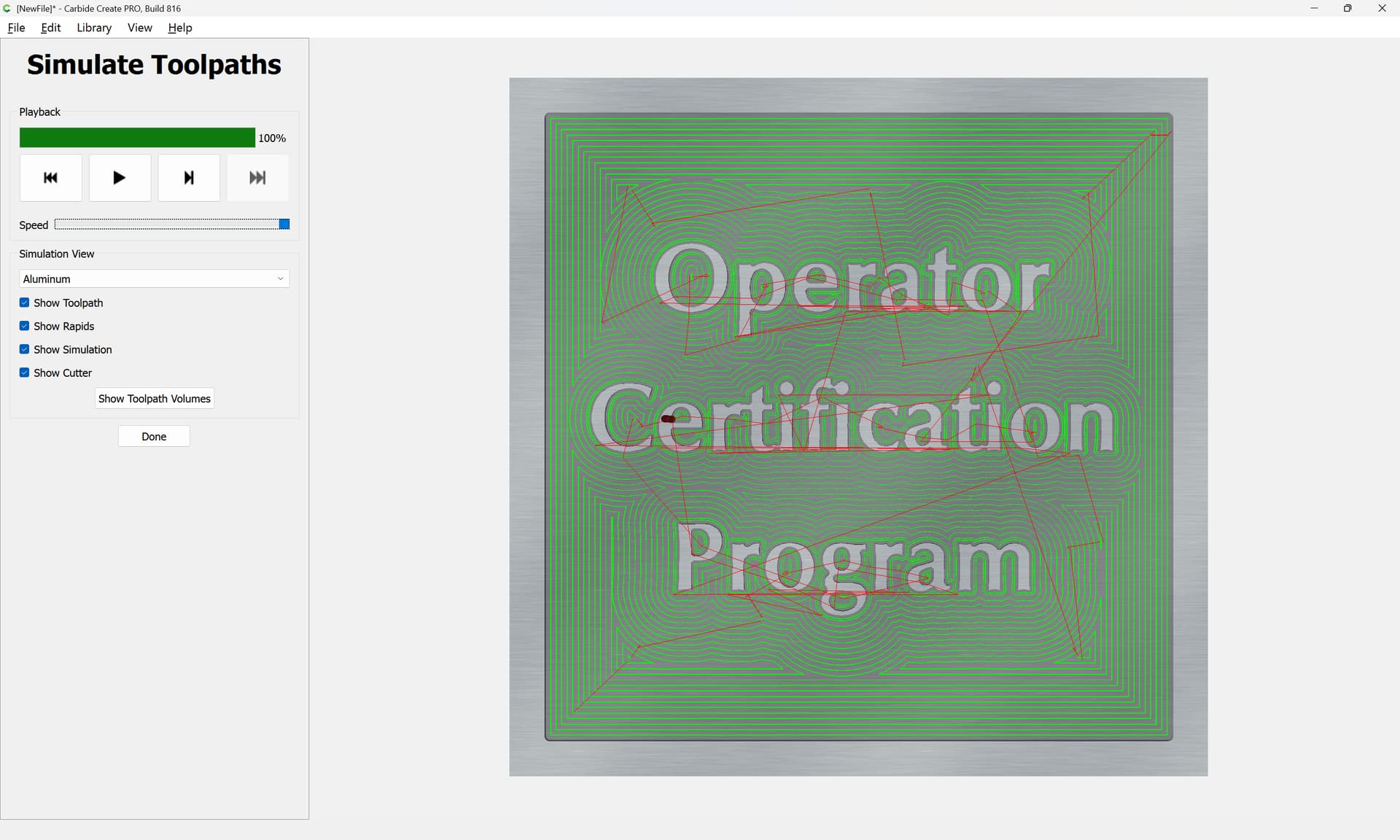
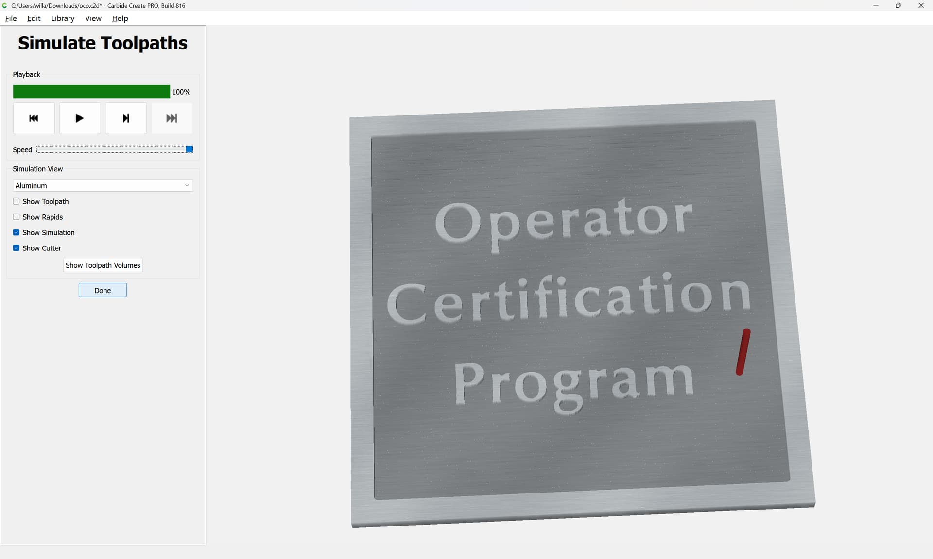
Check the simulation:
by clicking on “Show Simulation” as discussed at:
https://carbide3d.com/hub/courses/create/simulation/
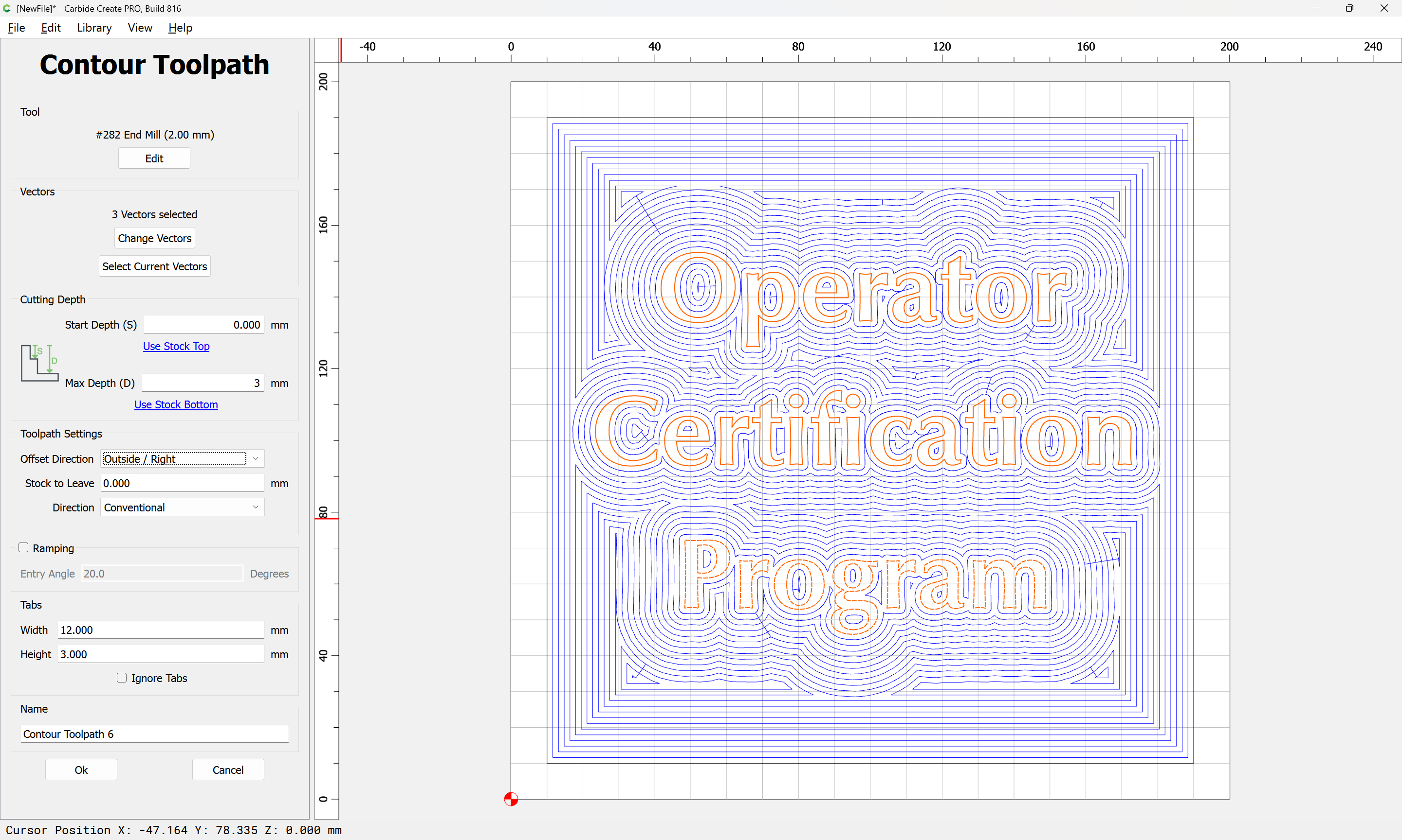
If it is not as desired, adjust the settings, or add additional toolpath(s) so as to arrive at the desired result:
Save the file to some location which you can access from Carbide Motion — if need be, place on a network or removable drive and connect to that from the computer running Carbide Motion.
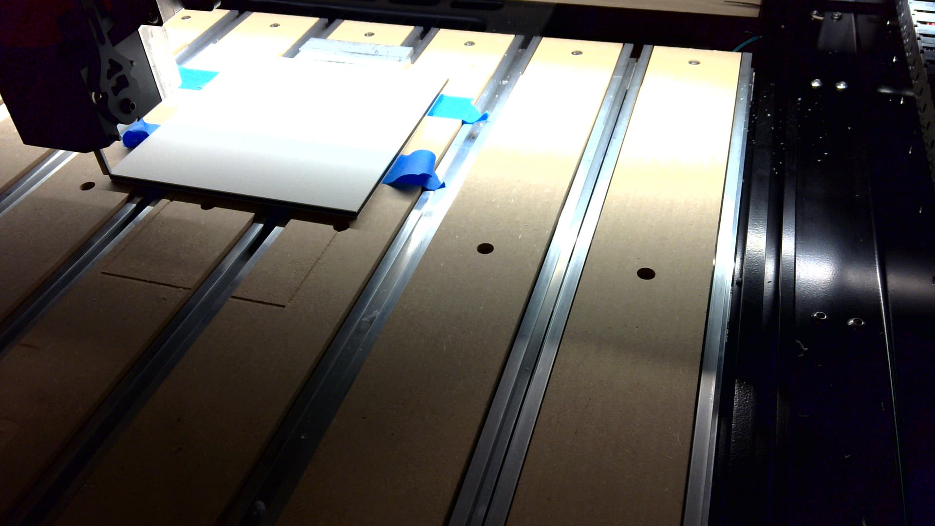
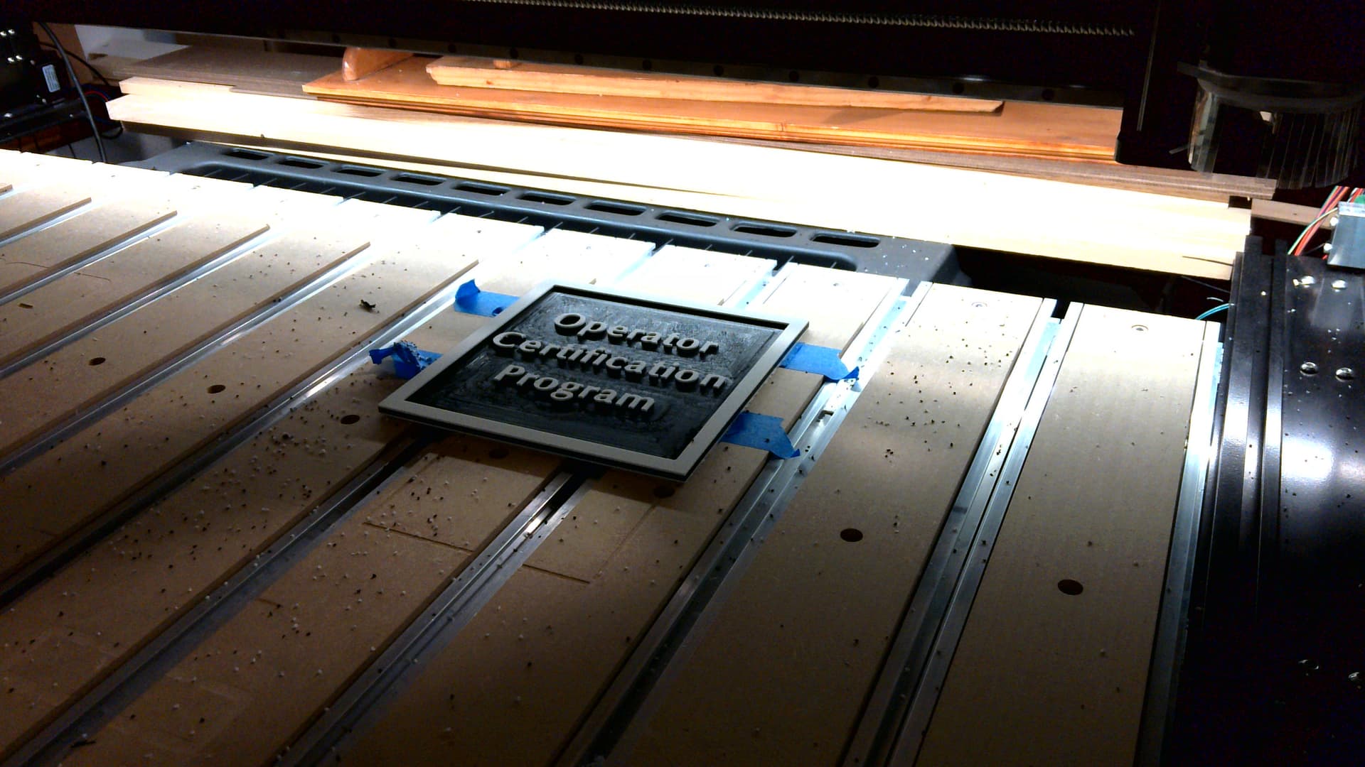
Secure your stock in place, ensuring that it is square to the motion of the machine and will not shift — since the material being cut is a sheet good which has concerns re flexing/bending, blue painter’s tape and cyanoacrylate glue will be used:
(note the metal bars being used as parallels against a lip machined into the MDF when surfacing)
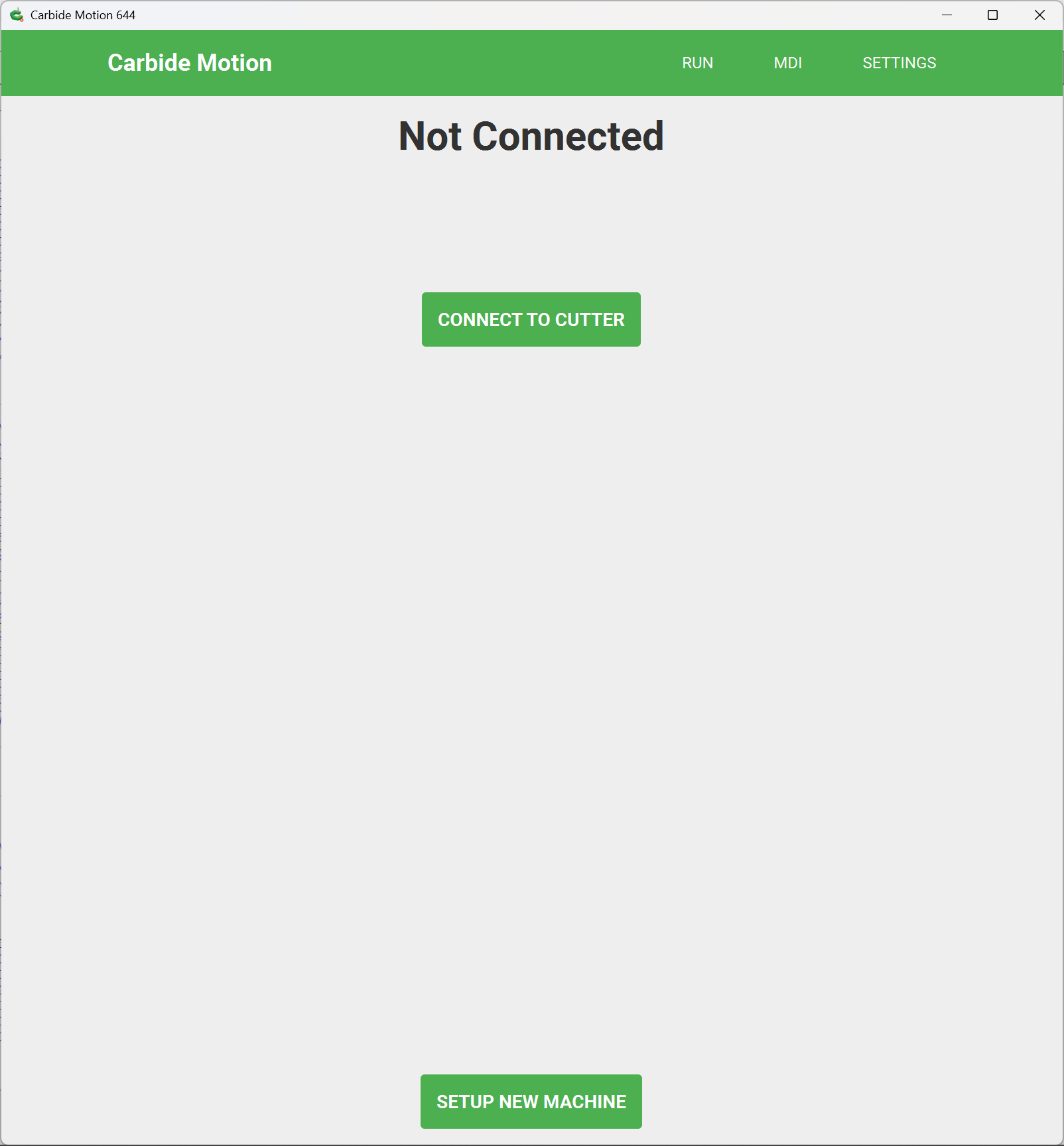
Connect the USB cable, power up your machine and launch Carbide Motion:
click “Connect to Cutter” to connect to the machine:
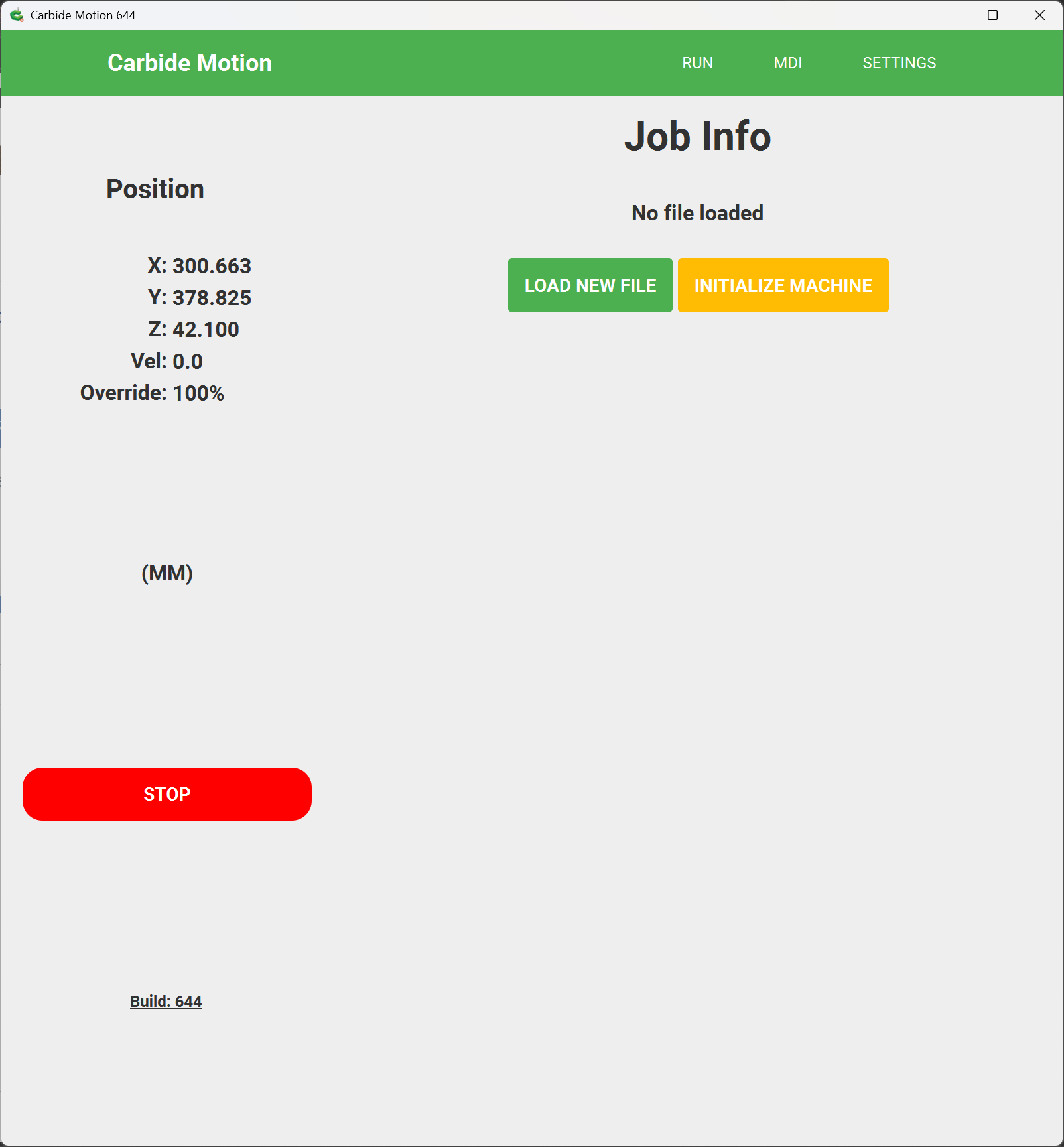
click “Initialize Machine” to initialize the machine — the machine will move to the back right corner, set the machine origin there, and then move to the tool change position:
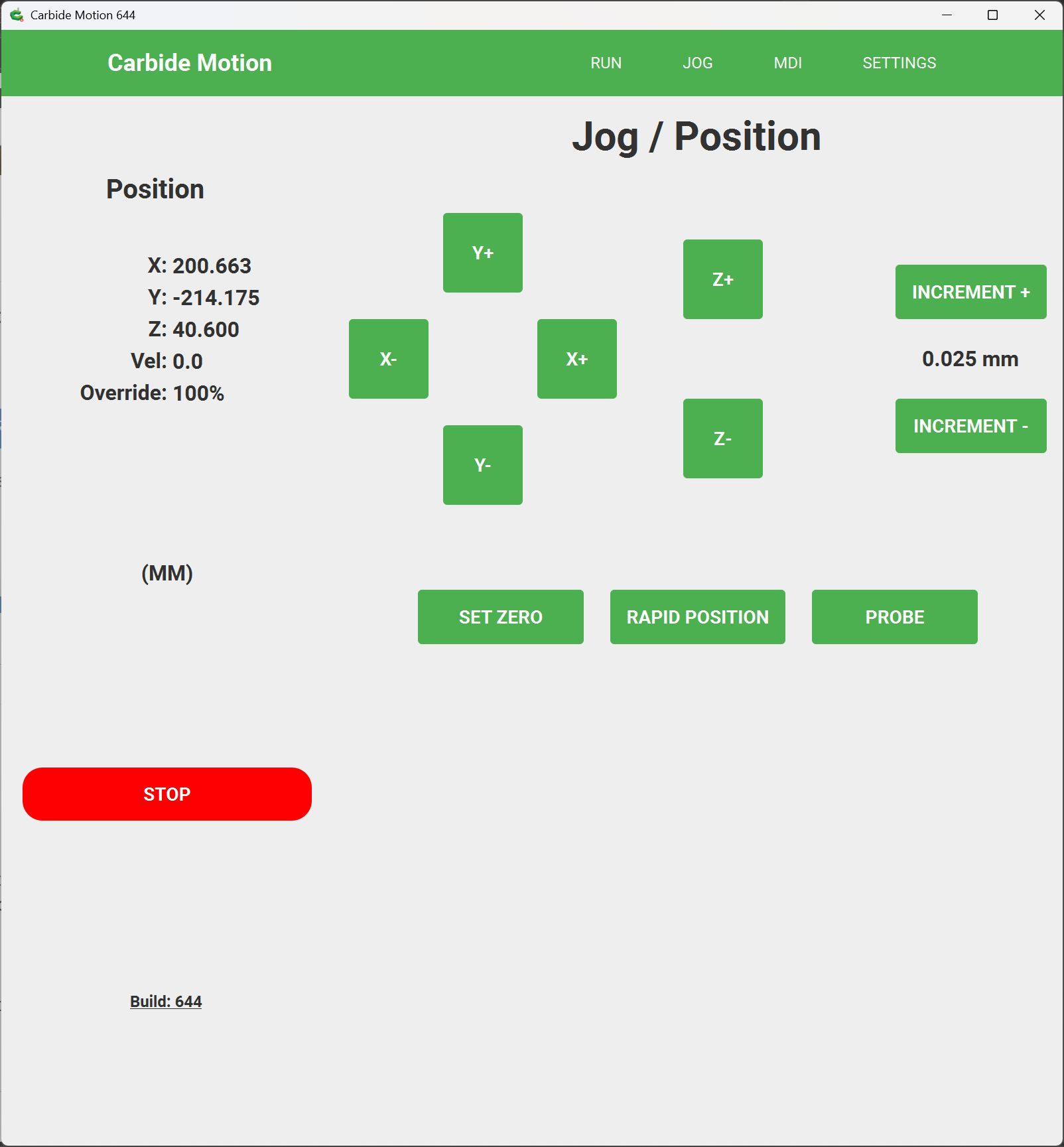
Load a tool or a probing pin and jog to the stock so as to set zero there to match how the origin is defined in Job Setup in the file:
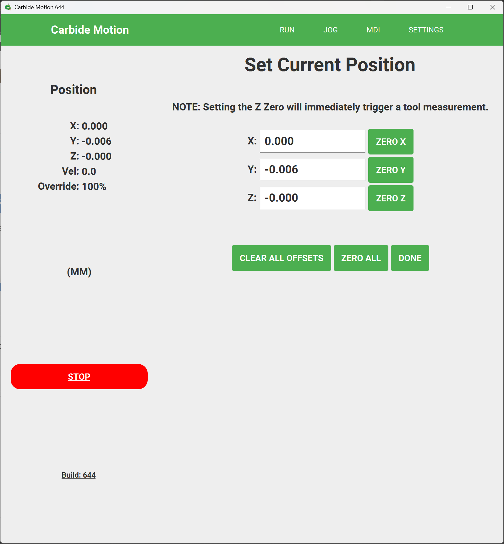
click on “Set Zero”
and set the Zero relative to the stock using the buttons for this purpose — or use a BitZero to probe for the corner as shown at:
For more on jogging and movements and setting zero see:
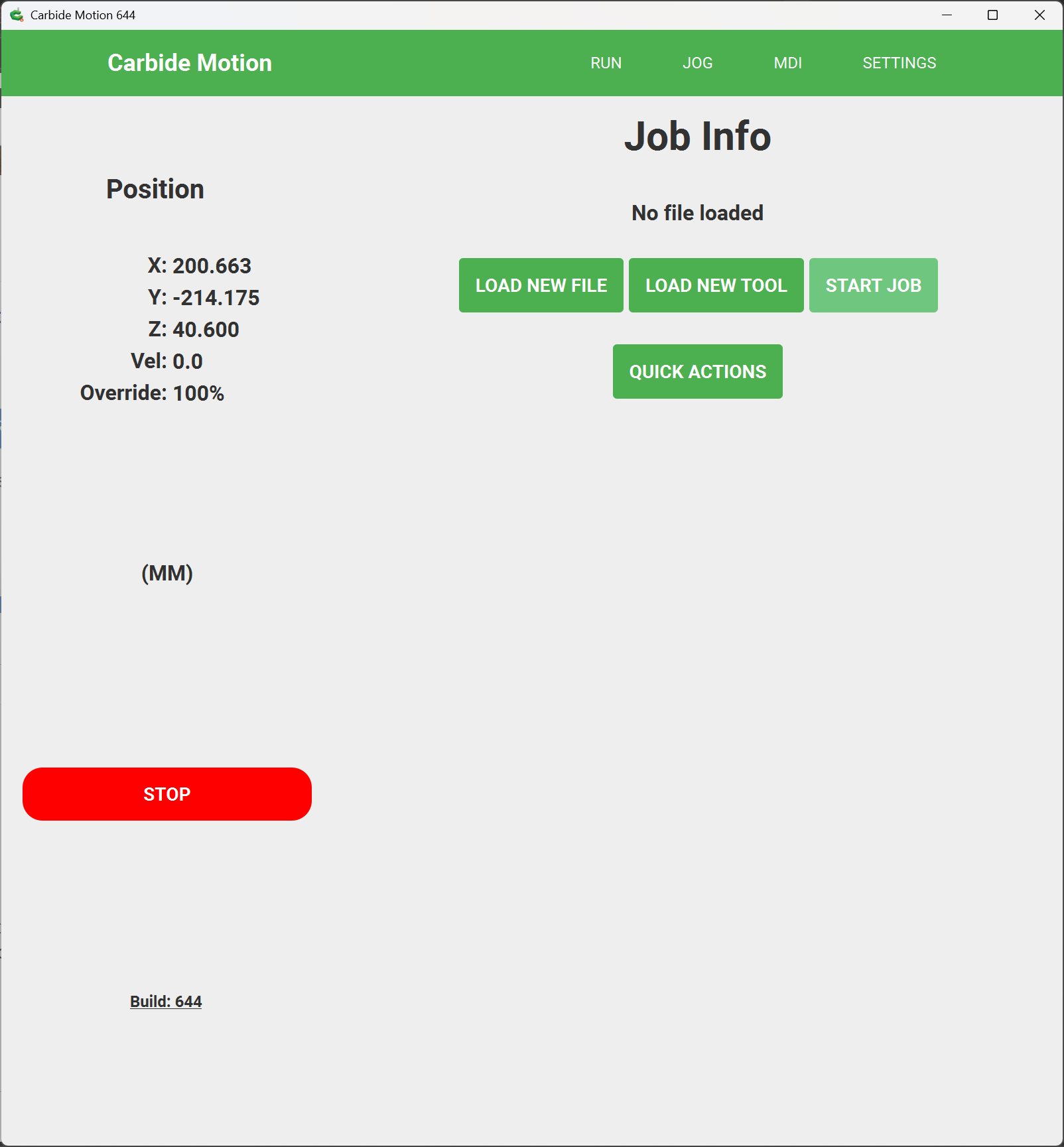
Click on “Done” and then return to the “Run” tab:
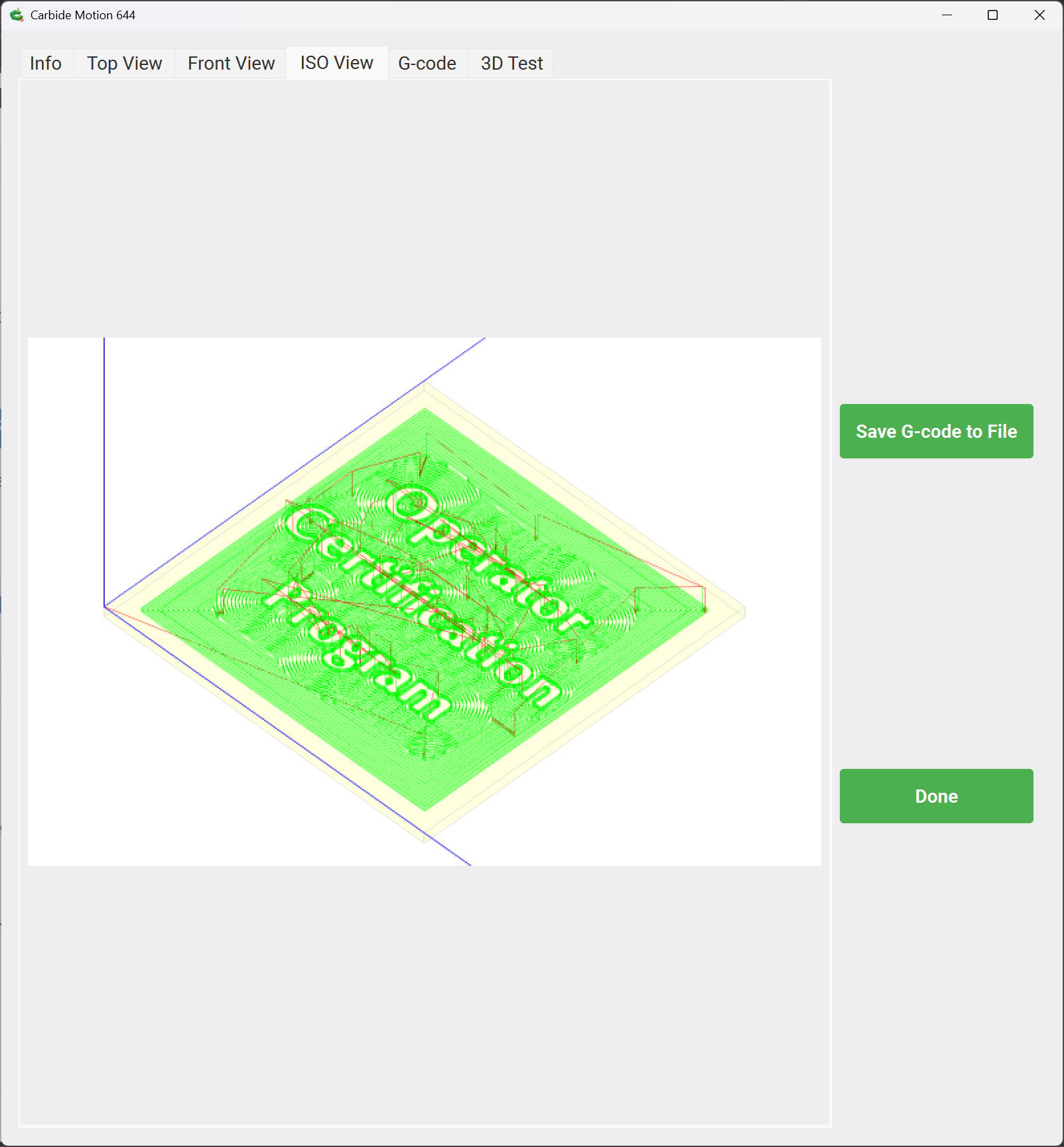
then click on “Load New File” to load a new file, selecting it using the file dialog:
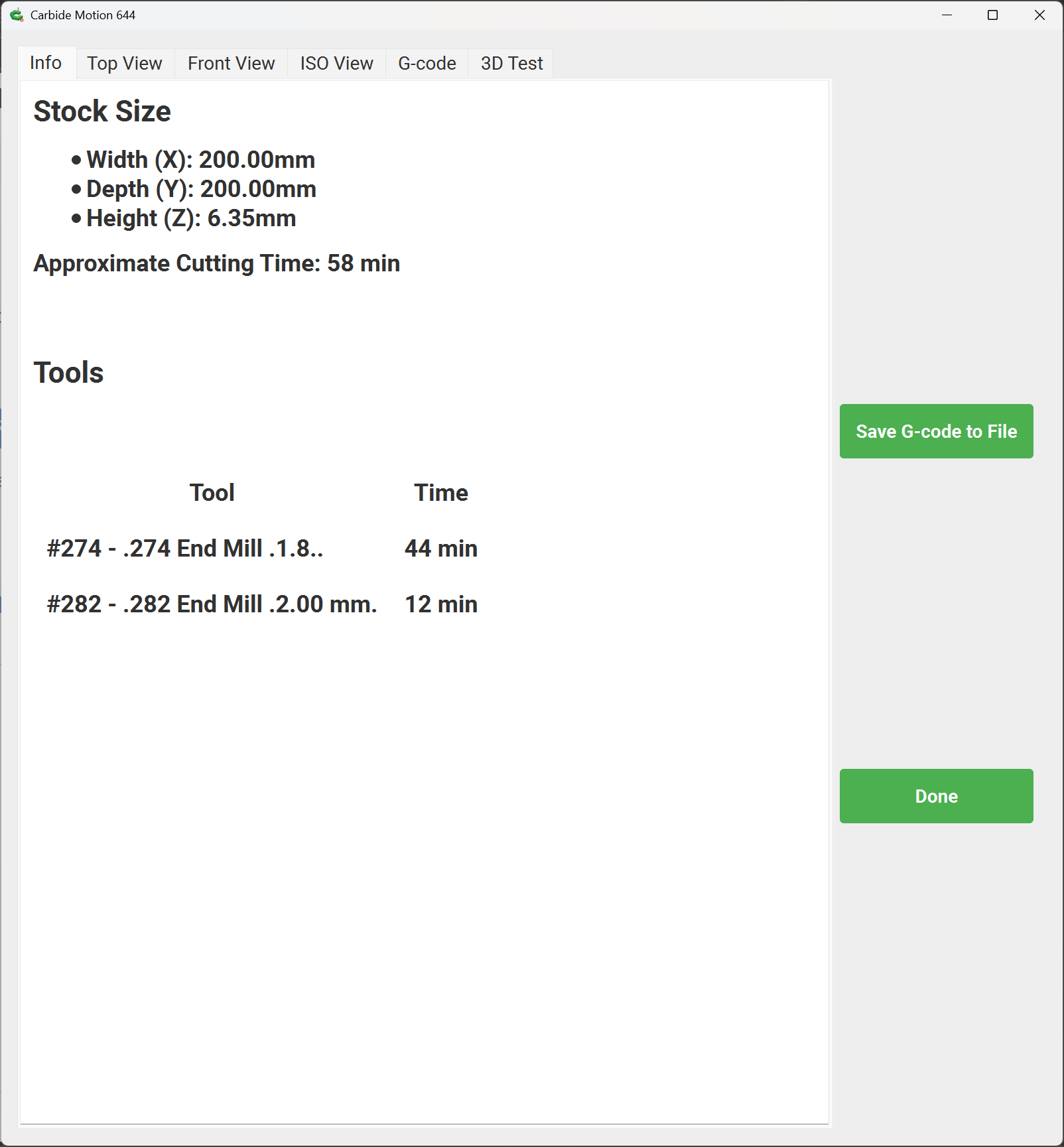
Review the previews and verify that the file is correct and that the origin in it matches the zero as set relative to the stock:
Done
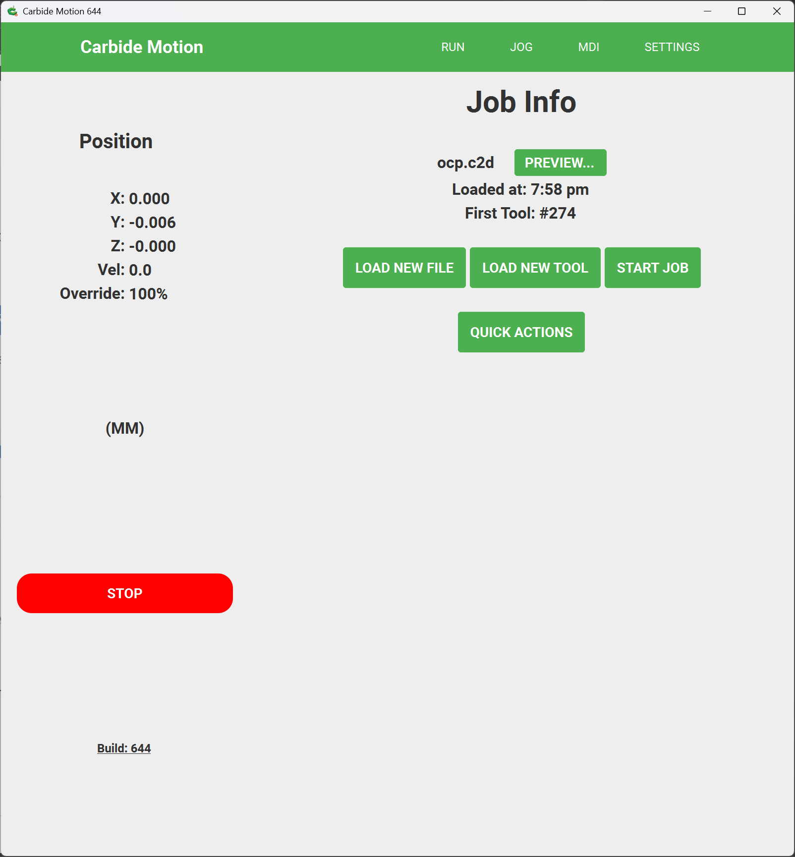
Click on “Start Job” to start the job:
then click on “Start” to start the process of cutting
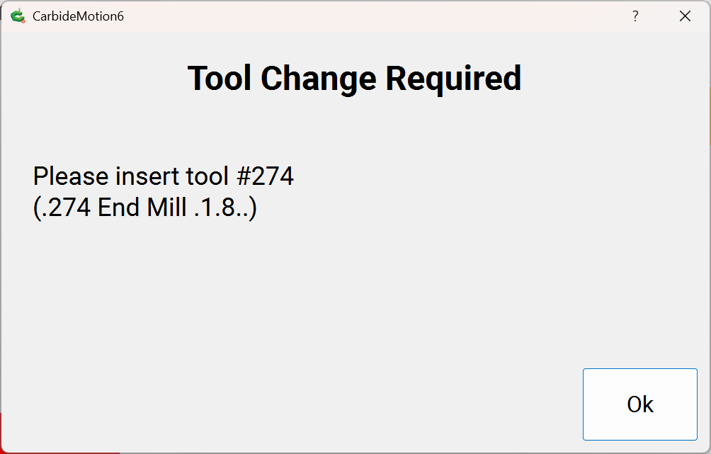
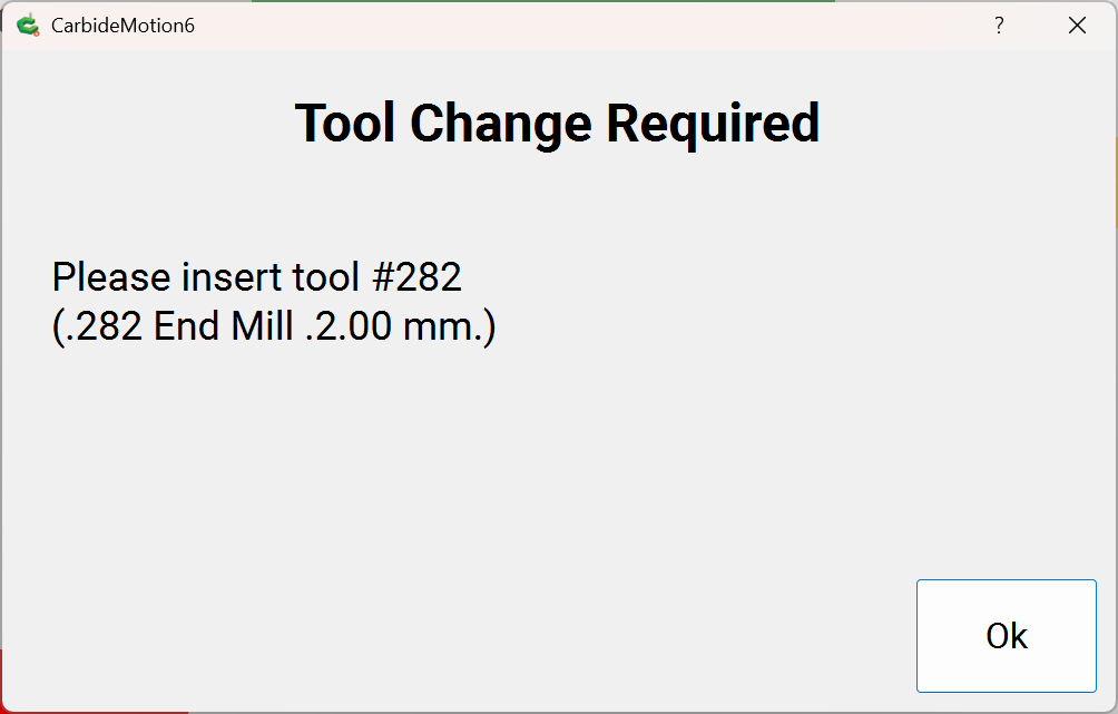
the machine will lift, and if a BitSetter is enabled, will move to the Toolchange position and prompt for the first tool:
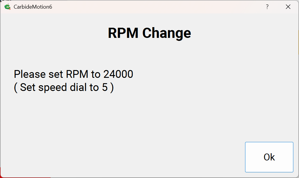
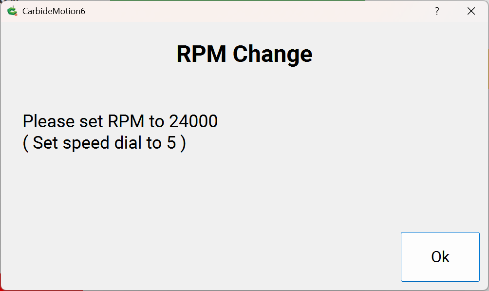
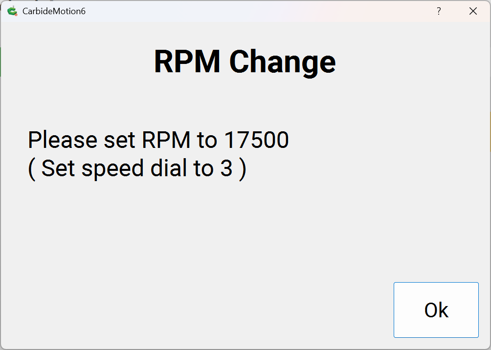
If necessary, load that tool and click “Ok” — the machine will measure the tool — if you have a BitRunner it will power on the spindle and prompt for setting the speed:
if you have a spindle, it will power on, set the speed, and so forth.
Don suitable PPE (eye and hearing protection at a minimum)
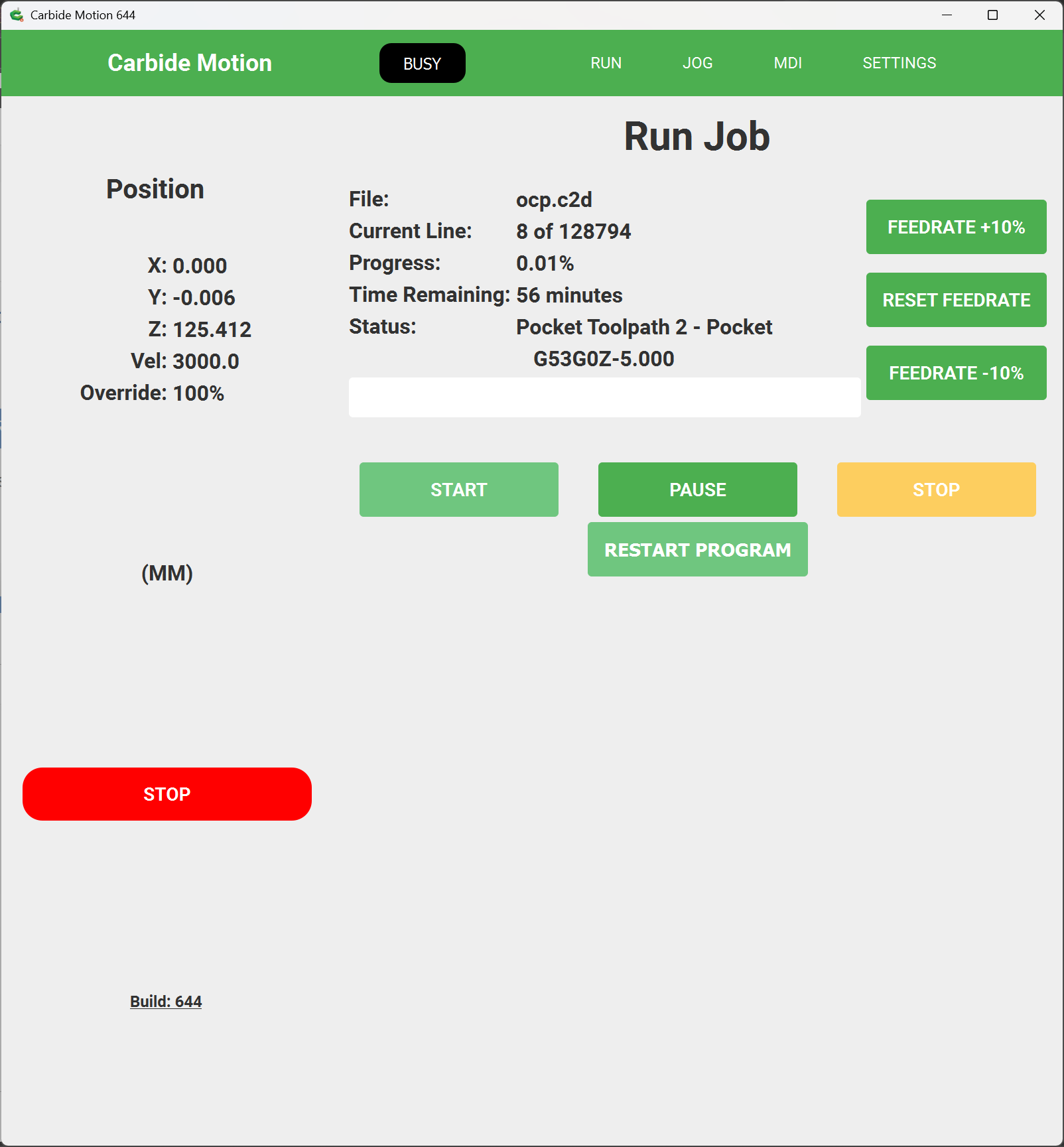
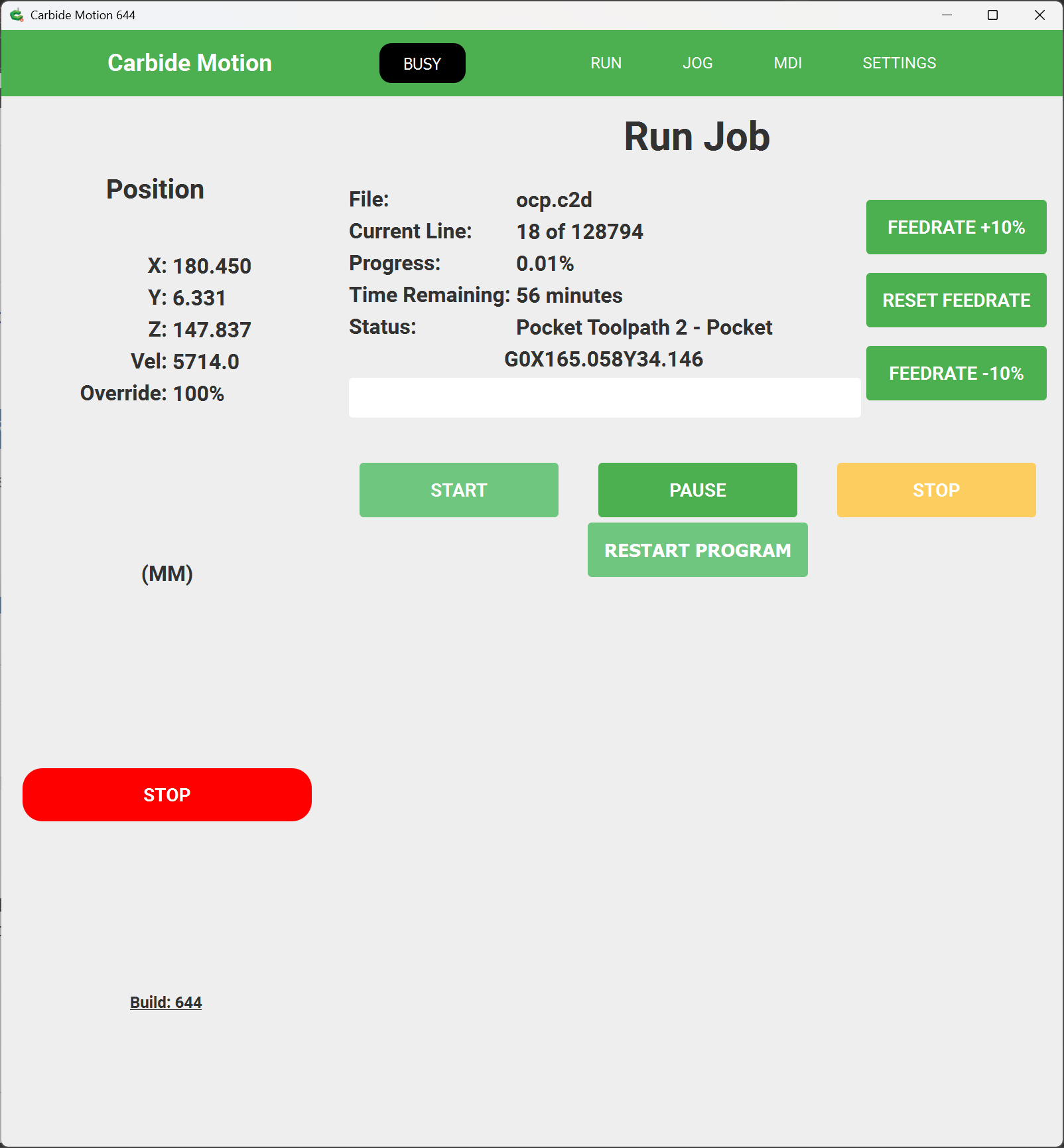
If need be, click “Ok” and the machine will begin cutting:
Monitor the machine as it cuts…
Once a tool is done cutting:
if there is a second tool, the machine will move to the Tool change position and prompt for the second tool (and repeat this process for successive tools):
Change the tool and click “Ok” to have the machine measure the tool using the BItSetter and repeat the process of power up, setting speed, and resuming the cut:
Ok
When the cut is compleat, the machine will lift, move straight back, and then to the right to return to machine origin:
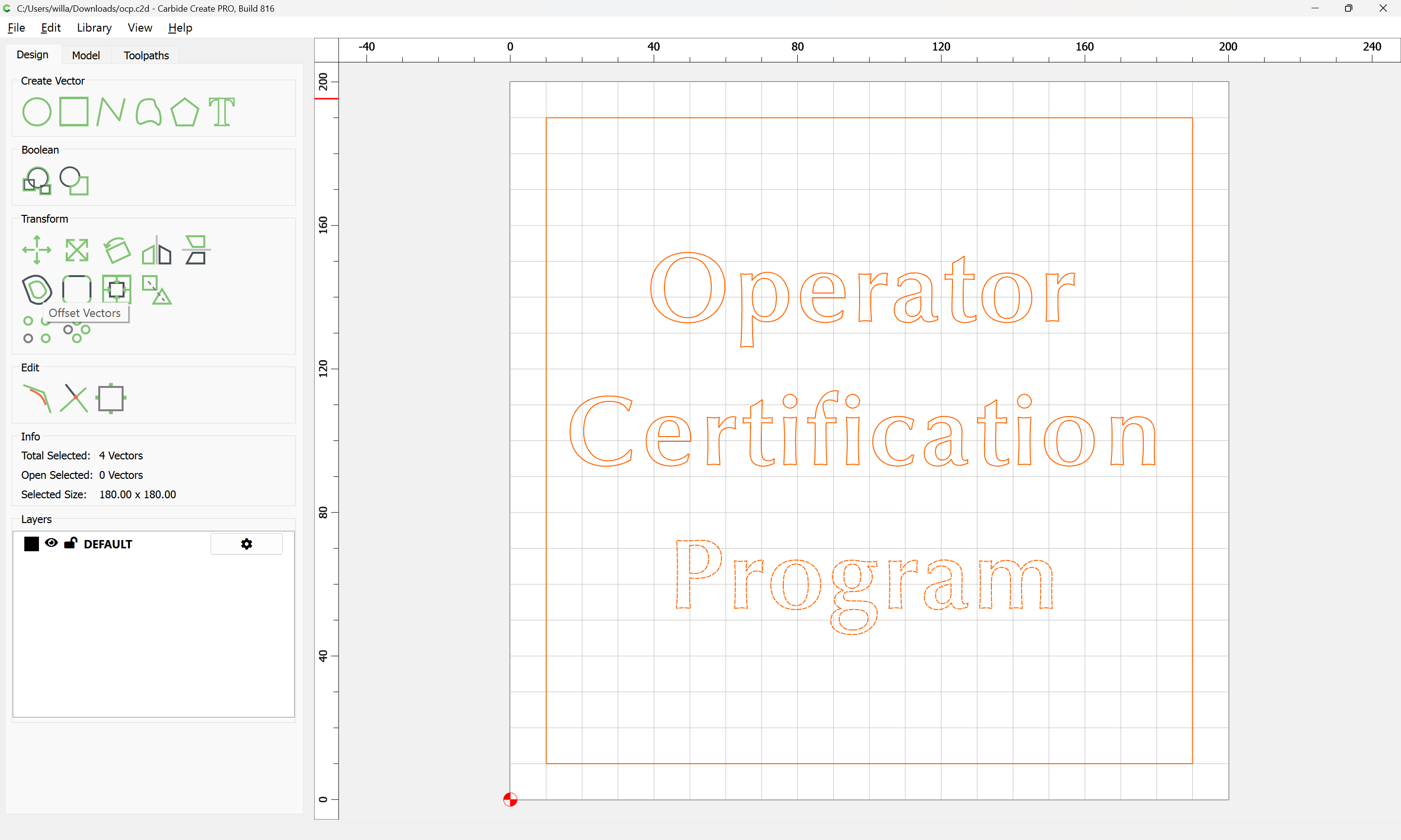
If there is anything further which needs to be done to the part using the machine, it should be done before removing it or losing the zero position — in this case we will return to Carbide Create, select everything:
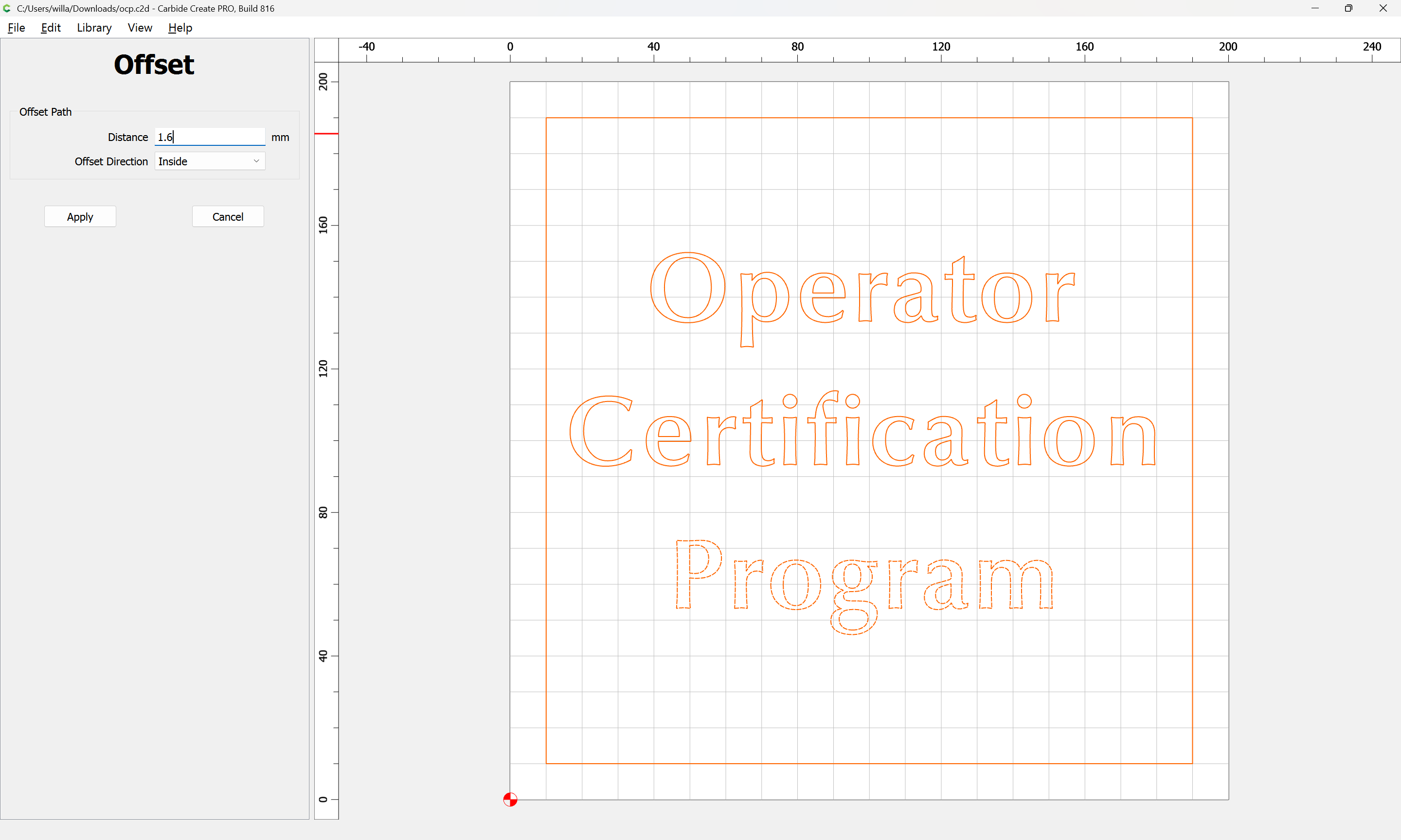
Offset Vectors:
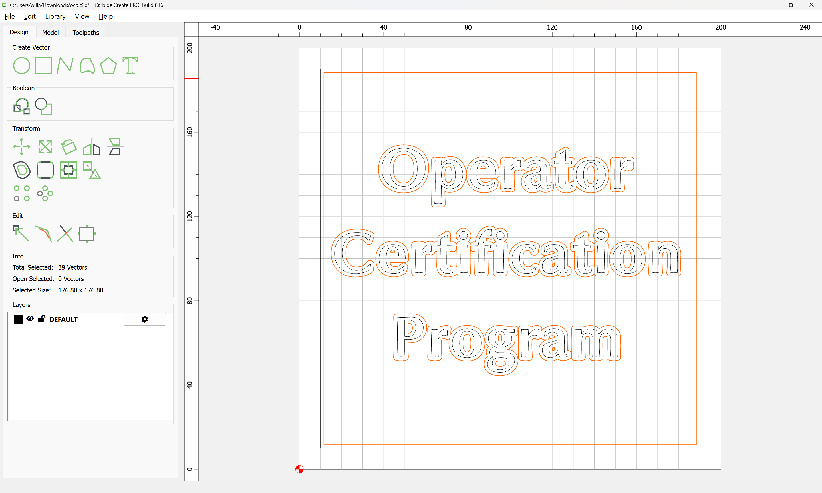
Apply
and apply a texture toolpath in an effort to remove the patterning of the Pocket operation:
checking the preview:
and adjusting as necessary until a reasonable result is arrived at:
then the second file is run with the appropriate tooling with the same zero as before (after disabling the original toolpaths)
Or, perhaps a 1.1 offset w/ a Facing toolpath:
This topic was automatically closed 30 days after the last reply. New replies are no longer allowed.