Project Swappable Controler Card-I knew that stuff was too cool to toss!

In perusing the forum at Carbide3D, I learned of another software package that added more utility to the Shapeoko package. It is called EstlCAM and the two parts of it that really grabbed my attention are, the Surface Scanning and Trochoidial milling. Engineers, you might want to head down to the next paragraph…warning, layman not just stepping in it, but playing Barney Fife…in a red shirt, on Star Trek…)Surface scanning allows the machine to scan a three dimensional surface and use the scan data from that scan to convert planar milling to actually fit the surface. Trochoidial Milling allows a machine to cut harder material than it can using conventional milling, by removing more material with a smaller cutting surface area-much like overlapping mower cuts when the grass is too tall from all of the rain…Go straight in to 100% tall grass and the mower boggs and stalls, overlap the previous cut and the mower keeps going! It takes more time and more fuel but gets the job done by lowering the amount of cutter contact(friction) To quote a web service I have seen, “Dude, I want That!”

One challenge to using EstlCAM with The Carbide 3D Shapeoko is that the accompanying software uses GRBL firmware and EstlCAm uses its own. The good news is that the Carbide Motion Controller has an Erasable Programmable Read Only Memory (EPROM) chip that can be relatively easily reprogrammed through connection the a computer and following simple instructions to erase and reprogram(also called Flashing) it for use with either Carbide Motion or EstlCam. If the use of one to the other is occasional, Flashing is the most economical way to make the change-because the time to change is a few minutes, by simply flashing the controller board. If the swapping between is constant, a quicker way to go is to setup a second controller board set up for the other one, swapping one board for another. One issue that would ultimately arise is wear on the connection points, the type of connectors used in the Shapeoko are designed more for occasional cycling(unplug/replug) than any sort of consistent cycling, add to that 10 connectors that have to be moved (3 for switches, 4 for stepper motors, one usb cable and a power cable) with each controller board swap.
A better answer is to use switches, allowing the contacts of the switch to deal with the wear of cycling on the connectors-something switches are designed to do!

One of the more skilled, patient and experienced Shapeoko owners, Jim Amos (jimidi) made up what I believe is the ultimate way of doing this here: What's better than ONE CM controller? Two of course He has it set up to simply insert a three prong key that pushes three switches! I admired and even lusted after his setup, but knew what had taken him a good bit of time to plan, collect supplies, execute and polish, would be more of a time challenge to me than the more immediate answer I needed.

So, I considered how I would set up an efficient act of board swapping, and what would I need? I looked around my raw materials area(my Pile of stuff too good/cool/expensive to just throw away) for inspiration, and found something interesting!


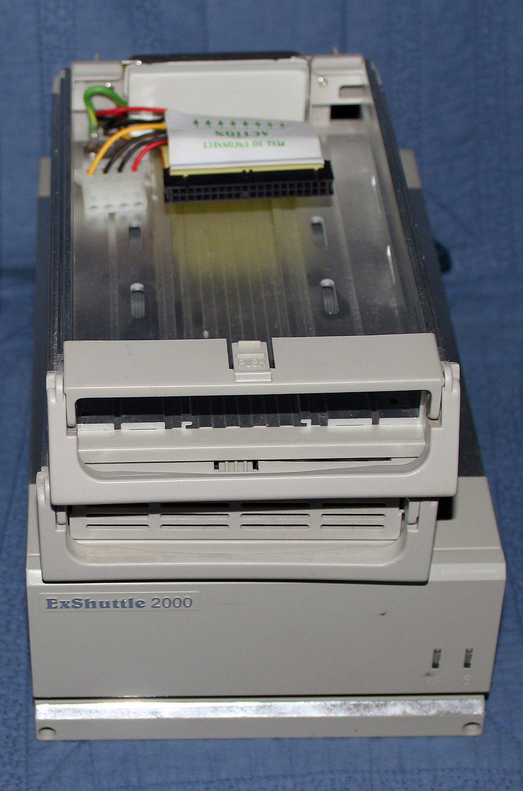
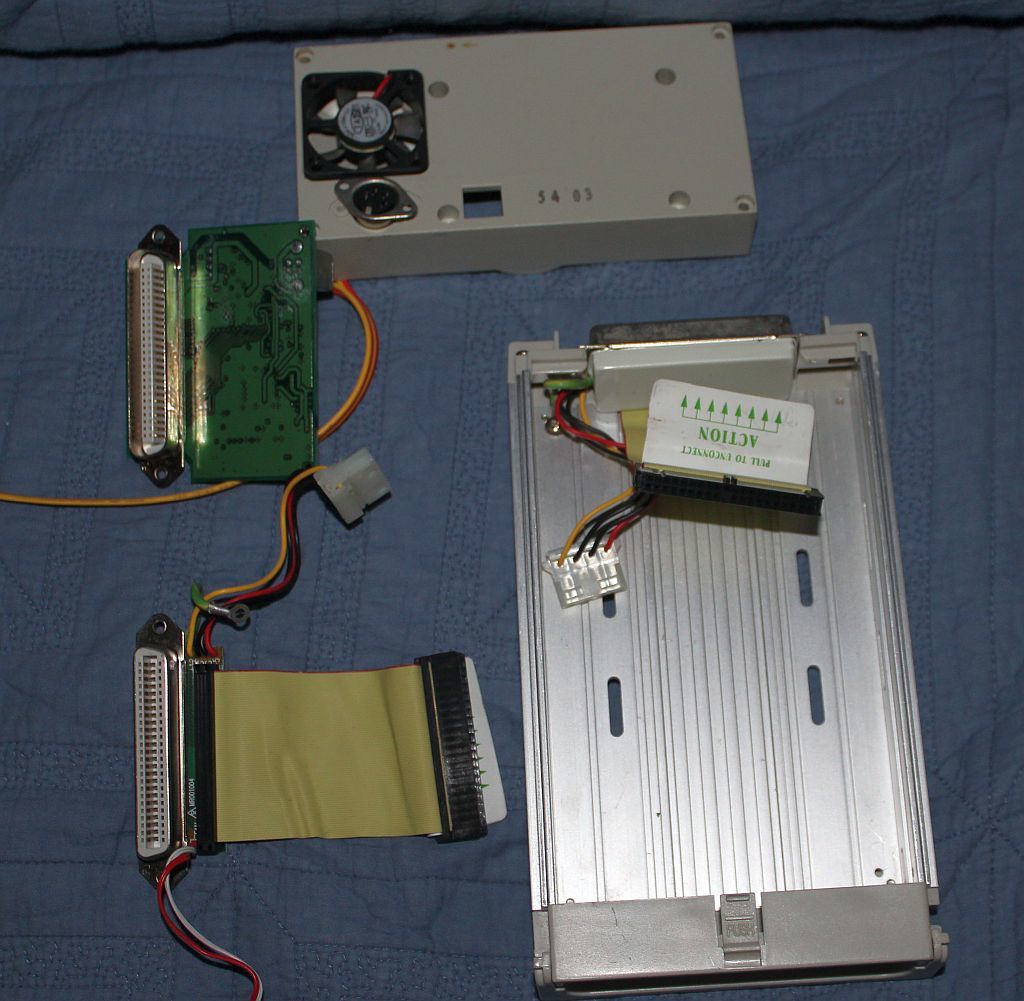
An EXShuttle external removable hard drive system with several trays, eyeballing it, the tray looked just big enough to accommodate the Carbide Motion Controller Board! So I took it over to the Shapeoko took took off the board cover, opened up the shuttle drive tray, and looked at what I had to fit in what space-they looked companionable…OK, Next I counted connections… The Shapeoko Motion Controller had 47 pins either labeled or not(not including those labeled expressly for the Nomad), and provision for more, and then there were 10 more connections for the power connector and USB connection. Bringing the total number of possible connections to 69-ahem. As it sits on my table the Shapeoko uses 22 pins for the motors and sensors, and two 5 connection plugs for power and USB-meaning I need 32 connections to make it work as it is…but…I want to leave room for add ons! When Carbide 3D offers Carbide Connect/Touch Probe/Laser head, yet to be announced accessories that I simply wont be able to refuse, I want to be ready! So I want an abundance of connections, I want to design the board swapping paraphernalia to be as upgrade-able as my Shapeoko XXL!

SO I looked closer at the particulars of the External Swappable drive bay. What did it have that I needed?

  1. Was the drive bay actually big enough?
    So I broke out the Vernier Calipers and took a few Measurements
    Carbide Motion Board: 70.4mm(side to side) x 163mm(End to end including over hang of power connection) x 29.6mm (top of tallest component to lowest solder protrusion on the bottom of the board)-might also have to consider the length of the power and usb connectors that plug into the board
    Stand off between board and mounting plate 3mm
    Heat sink contact patch. 76Mm x 11mm x3mm
    Carbide Motion Board bolt Pattern rectangular 63mm x 152mm

Tray inside measurements: 102mm x 166*mm x 30mm
*an additional 14mm could be added to the 166 my end cap modification.

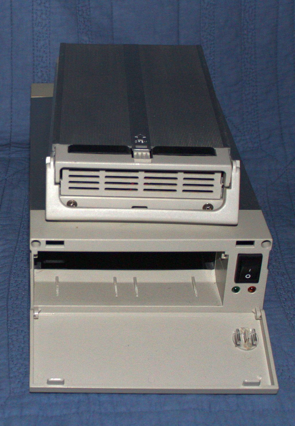
Would it be able to provide the needed heat sinking? both tray, and bay made from Aluminum extrusions with a fans for cooling! I will have to fab up and attach a heatsink contact between the board ad the aluminum tray-it also does not have the immediate thermal mass the Shapeoko heatsink does…

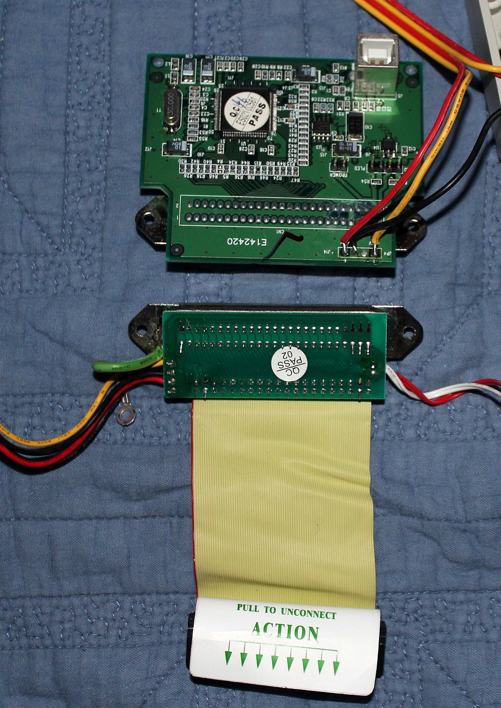
Electrical connections…DB50 connector already operational and high contact cycle rated…good for what I need now(42 connections) but possibly several pins short of what I could need to address future upgrades. Also I need to check the current rating of the contacts(in case I need to double some up). Looking good, but…still looking for a better answer.

Plastic end pieces are easily modifiable for necessary changes-and provide a positive lock in place pull handle!

Seems like I have a tool somewhere that could make good lookin’ holes in the plastic and aluminum as needed…

Looks like recycling this External Drive bay/tray combination t in several hours of work it would be a lasting solution and a great addition to my Shapeoko XXL!

To make this work I need to:

  1. De-solder the existing circuit boards from the DB50 connectors
  2. Connect the Motors and switches from the Shapeoko to the DB50 connector Drive Bay
  3. Connect the pins and connectors from each of the Carbide Motion Control boards to the DB50Connector in each of the two Removable Drive Trays.
  4. Flash the Second Carbide Motion Controller board Install the boards one at a time and test.

I want the wiring to be clean, orderly and easily follow-able. So I am considering alternatives to an extended writhing mass of 50 noodles in each small confined area…
Ideas:

  1. make a Printed Circuit Board to replace those already on the connectors to handle routing for each piece-meaning I need three Printed Circuit Boards, because they are each for the same circuits, they can be copies of each other, and add right angle usb plug-to minimize use of space, and a pair of Power connectors
  2. Order new DB50 connectors, made to crimp on Ribbon cable, order a 50circuit foot long SCSI cable, lose the installed ends, crimp the DB50 on, and apply appropriate connectors to fit to the headers on the Carbide Motion Controller board. Add a right angle usb plug, and a 4pin Power connector

To prepare for all of this I needed to Get some supplies on order.

  1. A second Carbide Motion Controller, so I contacted Carbide 3D sales via email, and Jorge(he is a really good egg!) emailed me back with the treasure map to ordering a second controller and after a few minutes. I had a second controller board on the way!
  2. Connectors (still hunting Stepper Connectors) But others are on the way!
  3. SCSI Ribbon Cable 60 trace on the way(seriously cheaper than a 50 trace version) on the way!
  4. Two Right angle usb plugs on the way!
  5. Several Power connectors on the way!

If you see something I missed, sharpen a stick and poke me with it!

Also in keeping with the Mayberry theme, I believe I can see several of you in this clip,see if you can?

6 Likes

Wow, William, that is an enormous project… I read it and can’t see it for all the trees (my cateracts don’t help niether. Anyways, I wish you luck and you got Jim as an excellent provoker… I’m not allowed any sharp sticks but that’s why I use that software exclusively. Good Luck buddy, I hope you the best success with it.

2 Likes

Jude,
I appreciate the support-and the trail Jim blazed!!! In lieu of a sharp stick, a swift kick in the backside has been known to get my attention as well.

The new board should be here mid week, when it comes in, I’ll replace my current board and verify it, then flash it and verify the flash, and then get on with the setting up the mounting and heatsink in the tray. Once the rest of the parts get here I will wire it up-and while I am waiting I will hunt down my solder vac, and de-solder the DB50s and test their current ability, My hope is that It will go quickly-that said, it has been quite a while since I built my last Heathkit…

2 Likes

Ok, in struggling to flash the new board last night I noticed the new board was getting warm …much warmer than the mounted board-but no where near hot, so I suspended the flashing attempt and slathered the back of the aluminum mounting board with Heat sink Compound and clamped it to the aluminum Drive tray(sorry no Pics-too focused on progress, not documentation-light bulb! for past assembly instructions…), it never got hot, but it did get warmer-and this was not a but a few minutes I worried about the heat from a potentially hours long cut…so I started questioning the Drive Bay/Tray mounting. SO I started considering alternatives… and it hit me, Carbide already designed in an answer to the heating issue…the thermally massive aluminum Rails on the the Shapeoko…I am looking for a compact answer…why not mount the second controller to the same rail…only one controller will have power at the time…so I will not be adding to the heat load, but moving it around a little on the rail. The original controller is mounted with two bolts, no reason I can’t add two threaded holes in line with those that were designed in…and create a cover large enough to cover the boards…and some sort of plug or switch mechanism. I would be adding thermal mass and surface area without changing the effective foot print…In keeping the same profile from the front of the rail I would actually need less available space to do this!
I would much rather have a single switch to throw than a plug, but I so far cannot find a switch with the needed number of poles with a double throw…
If I had a greater understanding of making PCB boards with Carbide 3D Copper I believe the Shapeoko could make a contact board for a linear switch or wafers to add to a rotary switch kit to accommodate exactly what I need, but in the interim I can use the 50 pin Centronics connectors from the Drive bay/trays to get the job done! It would alos help in dealing with the two spacing types between the Centronics connector pins and the connector header pins on the controller board…anyway,
One big plug to move…not as elegant or simple as a single switch, but not four bolts and 9 connectors (that weren’t designed for cycling) either…I will see about drawing up the extended cover-I think it will be cool-I am going to use some fiber optic cable to bring the lights from the leds to the front, and contour the cover to allow the cable and plugs to be external…but within the frontal area…Obviously I had waaaayyyy too much exposure to now cheesy science fiction as a kid!
Might also be a great time to work out getting the boards inside the rail…WOW those While I Am At Its sure sneak up on a guy!

3 Likes

I get the trades here… it took months for me to decide and implement. Hope you get your bootloader operating… it should be a slam dunk, but… Good luck and I’m eagerly watching.

1 Like

Yeah, wow… I get so caught up with those “while I’m at it”;s that I usually forget what it was I was at… Good Luck, Jude

2 Likes

Thanks Guys!
After digging through Digikey/Mouser/Grainger, and every electronics surplus website I could come up with, I could not find a what used to be fairly common-a DIY rotary switch kit-or a suitable existing switch, so I trolled ebay and will be recycling parts from a set from a Vintage HP signal generator…I will use the hardware and frame and learn how to cut PCBS to replace the wafers…and if necessary cut new rotors…the newer switches are riveted/molded together, these vintage ones were bolted together making them readily and easily reconfigure-able.


With 9 wafers already set up and available space for more, I should be able to make up a non-shorting switch capable of switching everything-by keeping the machine useable through to process.
Part of what I bought a Shapoko for was to make what I could not find! In the mean time we have a Thunderstorm bearing down and when it has finished, I will get the rail drilled and taped, the board installed on it, and then get to work on flashing the board! I will be adding pictures of progress from this point on…back to the hurry up and wait…

4 Likes

Bootloader Failure…I think I am going to make those my new Curse words of choice! I am seriously finding out what does not work! I have been trying to flash directly to Estlcam, and getting only headache and a dent in my fingertip from holding either the “prog” button or the Z limit switch… Taking a break, before this happens… might have to call on Chris Knight to help me take a step back…and then a step forward…

Funny how the frustration from an un-met expectation of simplicity is so much more powerful than the frustration of issues with something expected to be intensely complex!

1 Like

Indeed, there’s always a rabbit hole encounter when you least expect it. Having been thru the same trauma I recommend just flashing a new bootloader so you can move on to the rabbit holes that are worthy of your consideration. Let me know if I can assist as I have an ATMEL ICE module.

1 Like

Jim, any help would be great, I am going to go back through my settings and then the threads with flashing instructions…my last pass through I found many of the links were bad, but I did see that there were a number of Site updates in progress, hopefully they are sewn up and I can get some good links… Worst case I would copy what is in my original board and paste it to the new one(both version 2.4D), then supersede it with EstlCAM firmware.

I took today off to get the AC back on line, but rain will be stopping that, so, I have a large portion of the day to make some SO3XXL Progress! Hopefully Flashing first, then some wiring prep for the switch(chose not to drill and tap for the new controller until I see how much depth the switch will require.), but still have harness work to do!
I remember when resetting an eprom was pull a sticker and shine UV through the window… The last Chip I burned was with a “Pocket Romulator”…both were simple…

Ok, just downloaded and unzipped the Carbide updater found here http://carbide3d.com/dl/v4/CarbideGrblUpdaterWin.zip installed it on the RCA Windows10 2gb tablet, and I get “This AP won’t run on your PC” I had downloaded it before so just in case I tried both downloads to the same result… Breaking for lunch…

2 Likes

Tried the updater a few more times, windows tried to update itself while I was in the throws of the first attempts and I made it hold off, so this time I let her rip, rebooted and tried the http://carbide3d.com/dl/v4/CarbideGrblUpdaterWin.zip again…still no joy! Emailed Support as I have followed all the instructions I can find…several times with resets and cold boots between.
As a side note, my AC blower motor just came in…with the rain…I’ll round up some supplies and start on the harnesses for the Control Board Switch!

2 Likes

Just found a great resource for rotary switches and parts…https://www.surplussales.com/index/Rotary-Switches.html Lots of other thought provoking stuff there too.

3 Likes

The mother lode for rotary’s! Great find…
Did you order from here, and if so what?
I considered a rotary solution but didn’t search very hard.

1 Like

I haven’t ordered anything yet as I had already found and bought the used set of three pictured above to get hardware. I figure I can cut new wafers on the Shapeoko if I can’t reuse what is there-they will be here tomorrow, and I will disassemble/clean and see what I have as a starting point. Since the switching needs only up to 5 amps. and each wafer is simply a odd shaped pcboard with plated grommets set in it, I don’t see any real difficulty in making them-once I sort out making the pattern… Copper Grommets are available here. I figure cutting thin copper plate wont hold any issue for the Shapeoko-if it does electroforming copper on and through a circuit board certainly is not outside my comfort zone-neither is plating it with something to keep corrosion at bay.
I would rather find a fast solution, but trying to find something already made for this dense of a switch is probably going to be futile, making this another project…
I also was shopping ebay and found these and ordered a set as well-a different variation(much higher density) on the rotary mechanism… http://www.ebay.com/itm/2-pcs-x-Vintage-NOS-Rotary-Switch-8P4T-8-Blades-Pole-4-Throw-S29-Pat-Pend-No/201430354402?ssPageName=STRK%3AMEBIDX%3AIT&_trksid=p2057872.m2749.l2649

Between both sets of switches I have not quite $30(with shipping) in the switch parts so far. Probably end up with a hybrid of the two kinds…though I have seen another variation that used Copper balls between the leaves to make the contacts…

2 Likes

Don;t forget to include some Blinkenlights for crowd appeal when these switches start rotating and whirling…

1 Like

ZO RELAXEN UND WATSCHEN DER BLINKENLICHTEN!

:stuck_out_tongue_winking_eye:

Dan

2 Likes

The Go Big or Go Home parts of me thought about blinging up the whole thing, faceting, polishing, and chrome plating the Colet nut then sending several colors of laser leds bouncing off of it, but at 15k-30k speeds what kind of a disco ball would that make? Then, If I did that, I would have to make a clear acrylic and under-lit vacuum infused Spoilboard,and add a a few strobes and serious sound system…then there is just no way to leave out a Fog machine at that point…and I would have to leave CHiPs, The Mod Squad, and Starsky and Hutch rotating through the screen saver…
I think the worlds first Disco Shapeoko is better left to the next hip cycle of hip-the BeeGees Sound track might be nice to hear ONCE!
That said, I have been thinking about optical conduits to carry light from the leds on the controller boards to the front of the machine-though putting a window into the controller cover and setting up a carbon dioxide fog fall to run across the leds does give me the same charge as both synthesizing excited bromide in an argon matrix, and seeing a 5 megawatt laser fire at lease once…

I thought about making a remote control too, and having the switch powered so when I use the remote to switch, the switch physically turns too-Hey! it was cool on a stereo I had years ago!

1 Like

Got to love it! That sounds like the perfect solution to watching a spindle glide back and forth and side to side, but where does the cnc machine fit into all this? Don’t forget the material handling equipment and auto loading, auto hold downing with gas operated actuators and weight sensitive material guidance system for that tedious task of switching material for each cut…OH NO there is that “switching” word again ! Oh well, I’ll leave you to your current switching endeavor. PS don’t forget the “A-Team” and “McGuiver”. …Jude

1 Like

Everywhere! everything I mentioned would be a Shapeoko Project! Could you see an episode where MacGyver or the ATeam actually had a Shapeoko! How many Busted Myths would have been made not just plausible, but easy?

1 Like