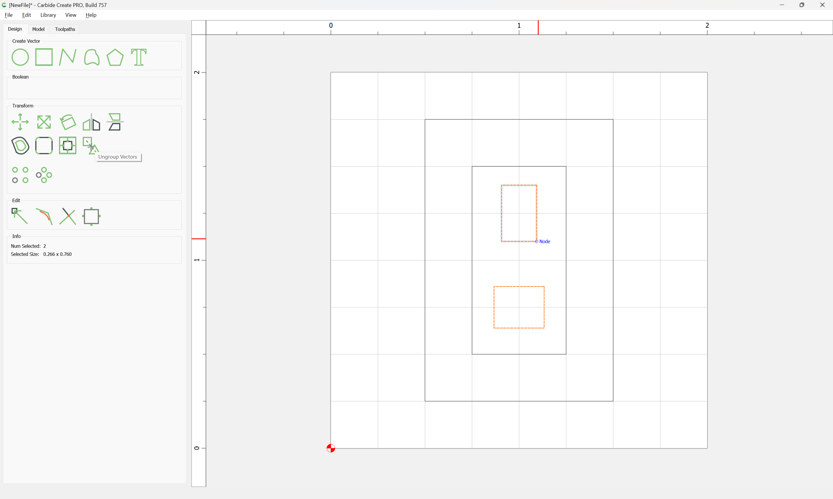
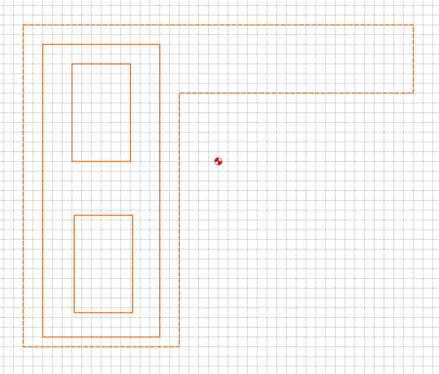
This seems like an odd bug. I have a few cuts where I’m cutting out the center of an item. In order to use up that space, I’m placing a smaller shape within it to cut it out to maximize my material.
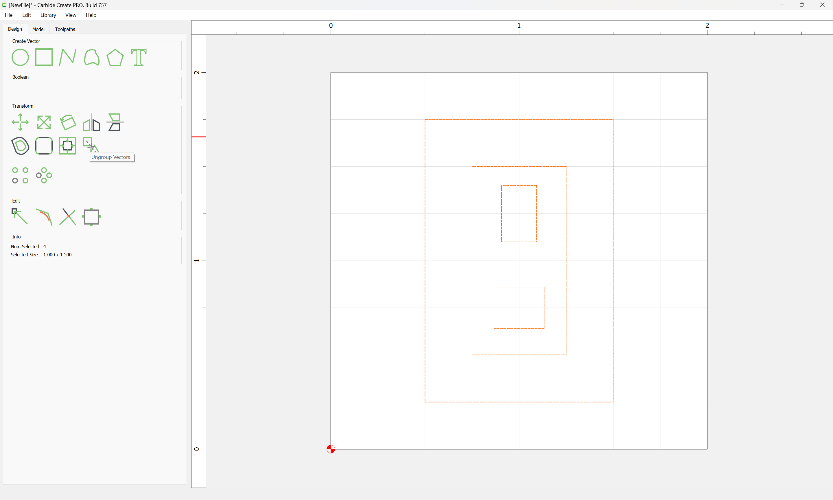
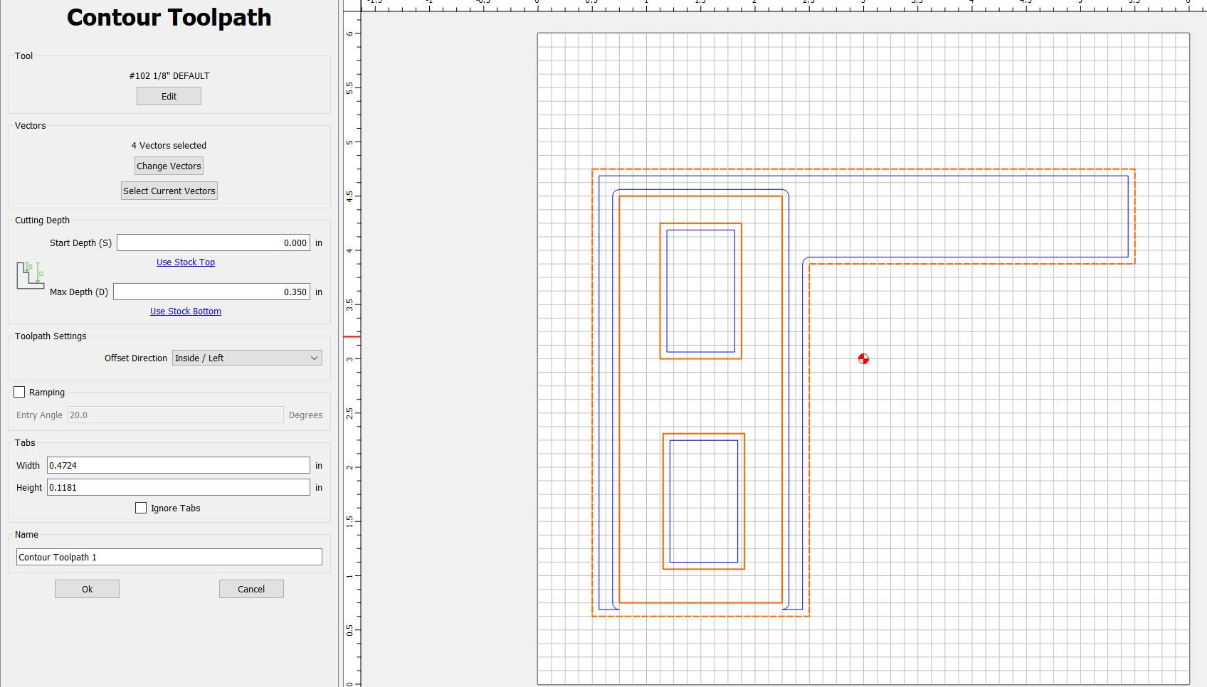
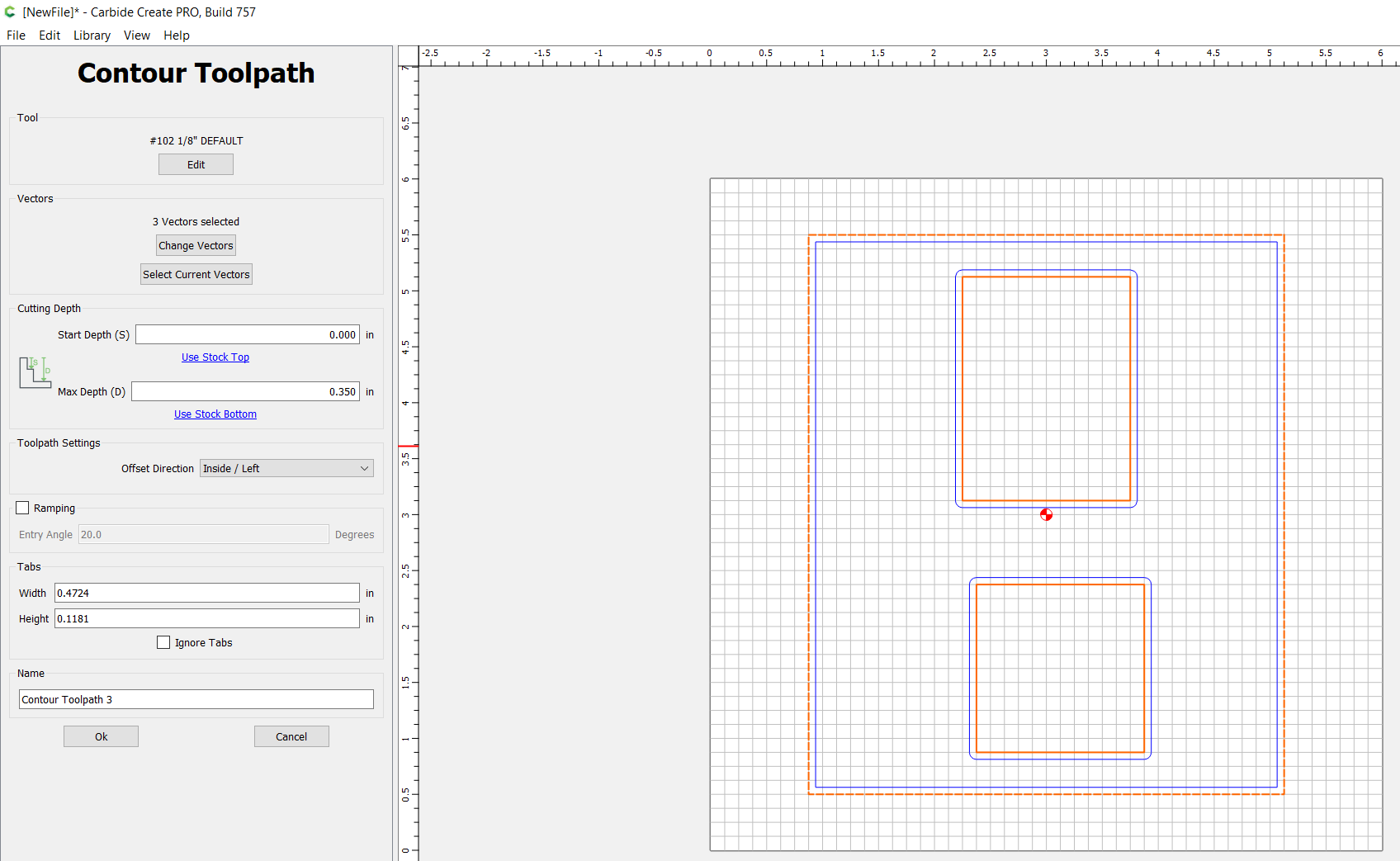
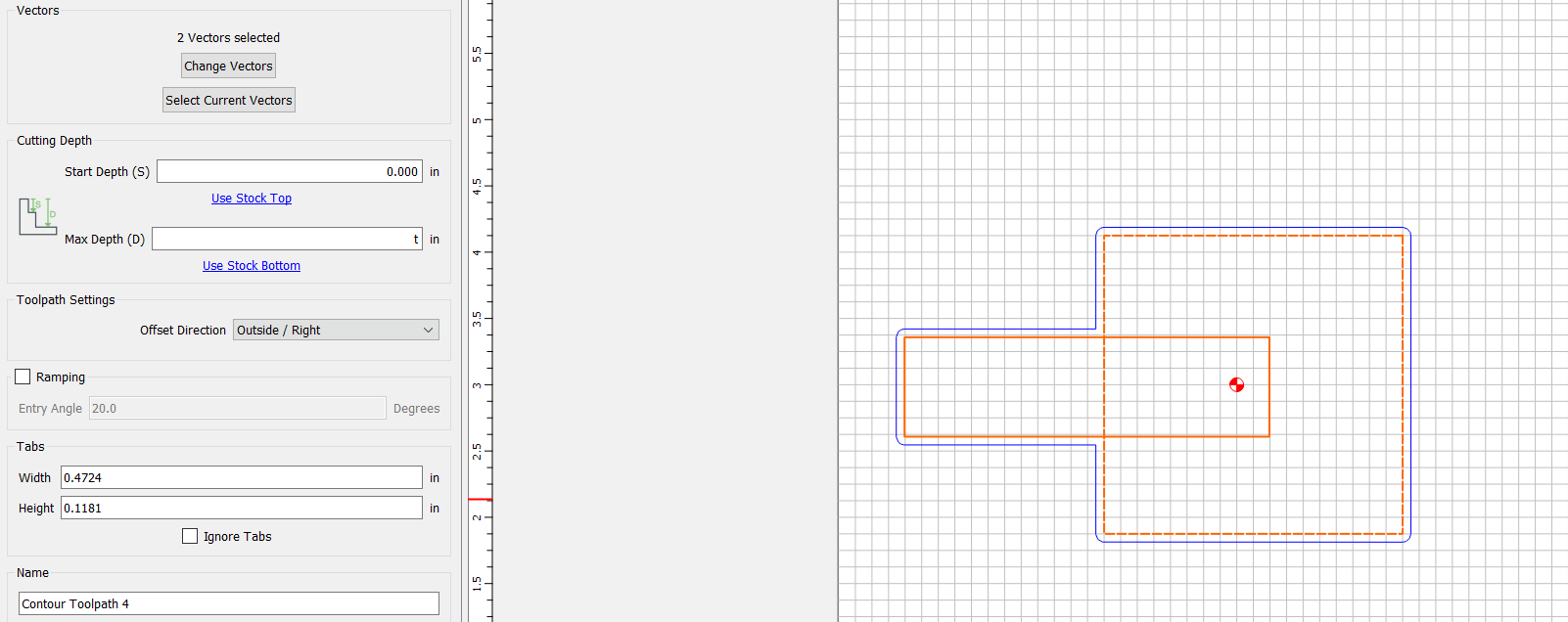
Whenever I create a cut with both Outside and Inside contour cuts, the shapes that are placed within the Inside cut, defaults to Inside contours, even though they are part of the Outside contour group. See screen shot. The Inside rectangles should have an Outside contour – shown with the group selected, but the blue cut line appears on the inside of the shape. This is not a glitch, and will actually cut inside the shape…much to my initial disappointment.
De-selecting the rectangles and then re-selecting them within the Outside group doesn’t fix it. The only way I cant get it to work is having a separate cut group that is ONLY those rectangles.
My best guess is that anything attached to a group, that falls within another groups “Inside” boarders, will default to Inside.
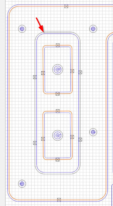
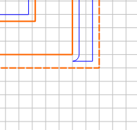
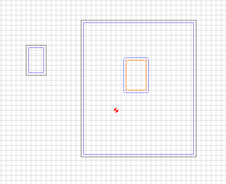
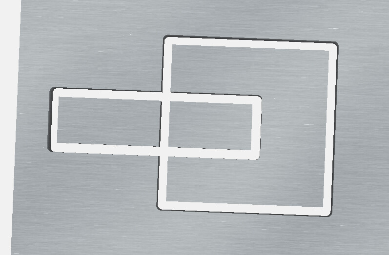
So it looks like it’s on the outside of the middle rectangle, but it’s actually doing the inside of the outer shape cut off by the middle rectangle…make sense?
In particular look at this:
Definitely not what was expected.
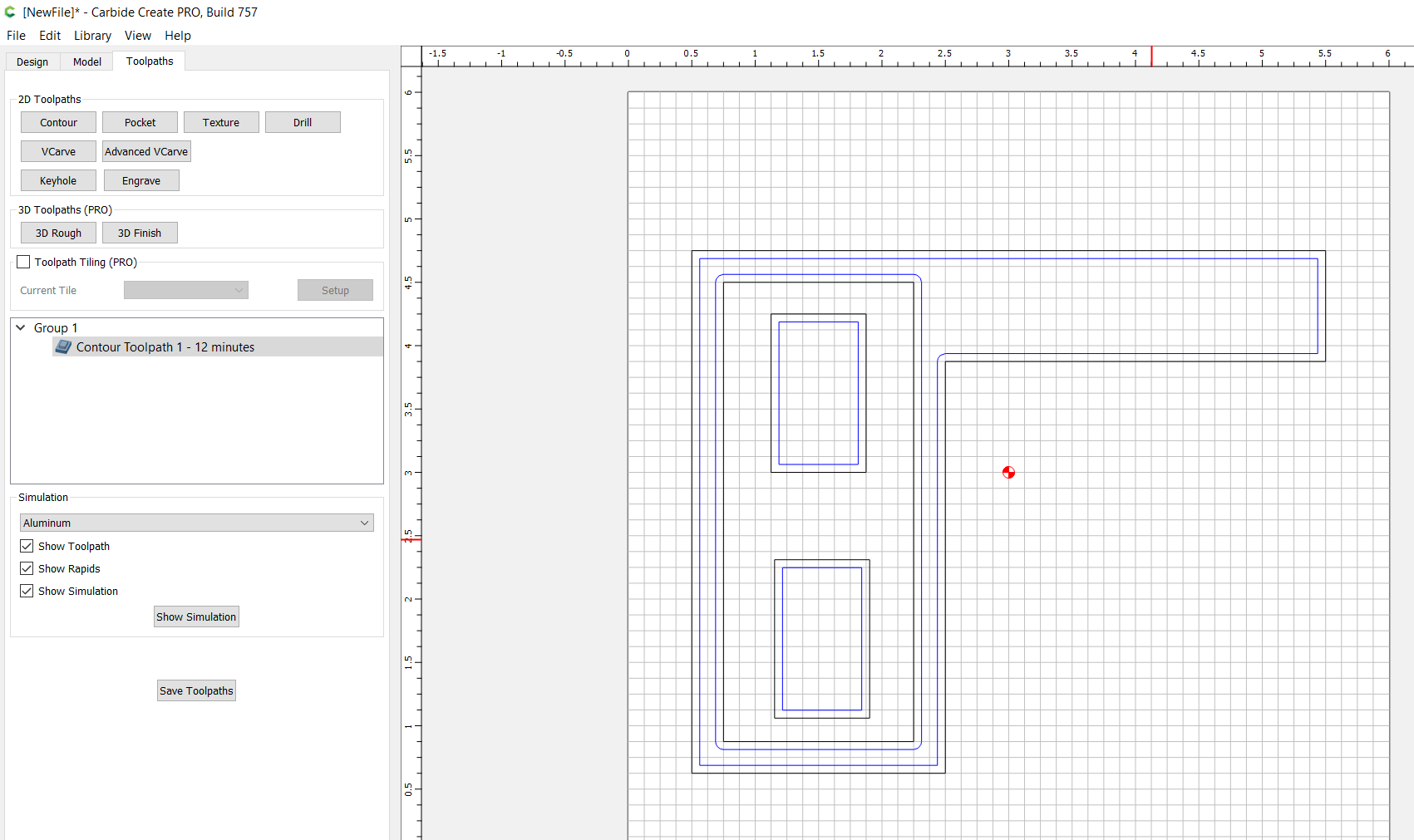
EDIT:
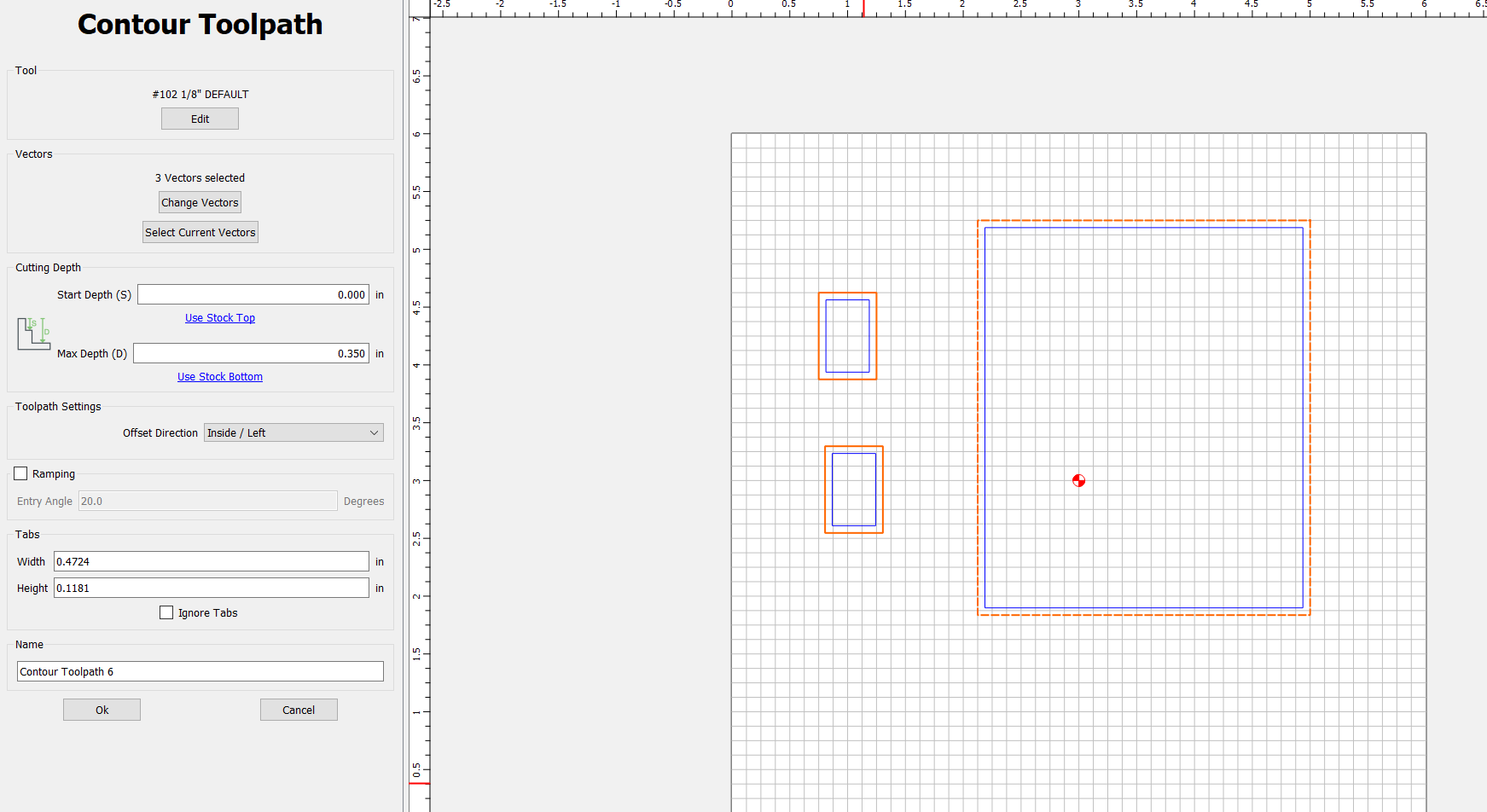
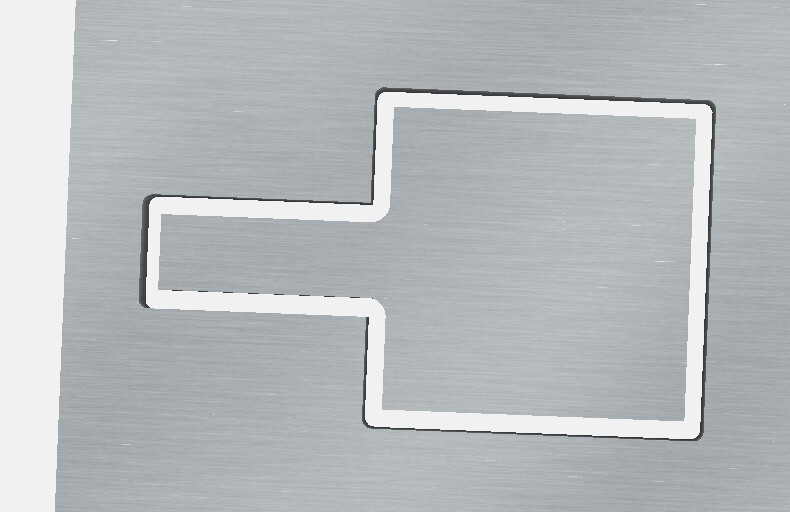
Then I shortened the middle rectangle so it wouldn’t interfere with the cutout of the outer shape and got this:
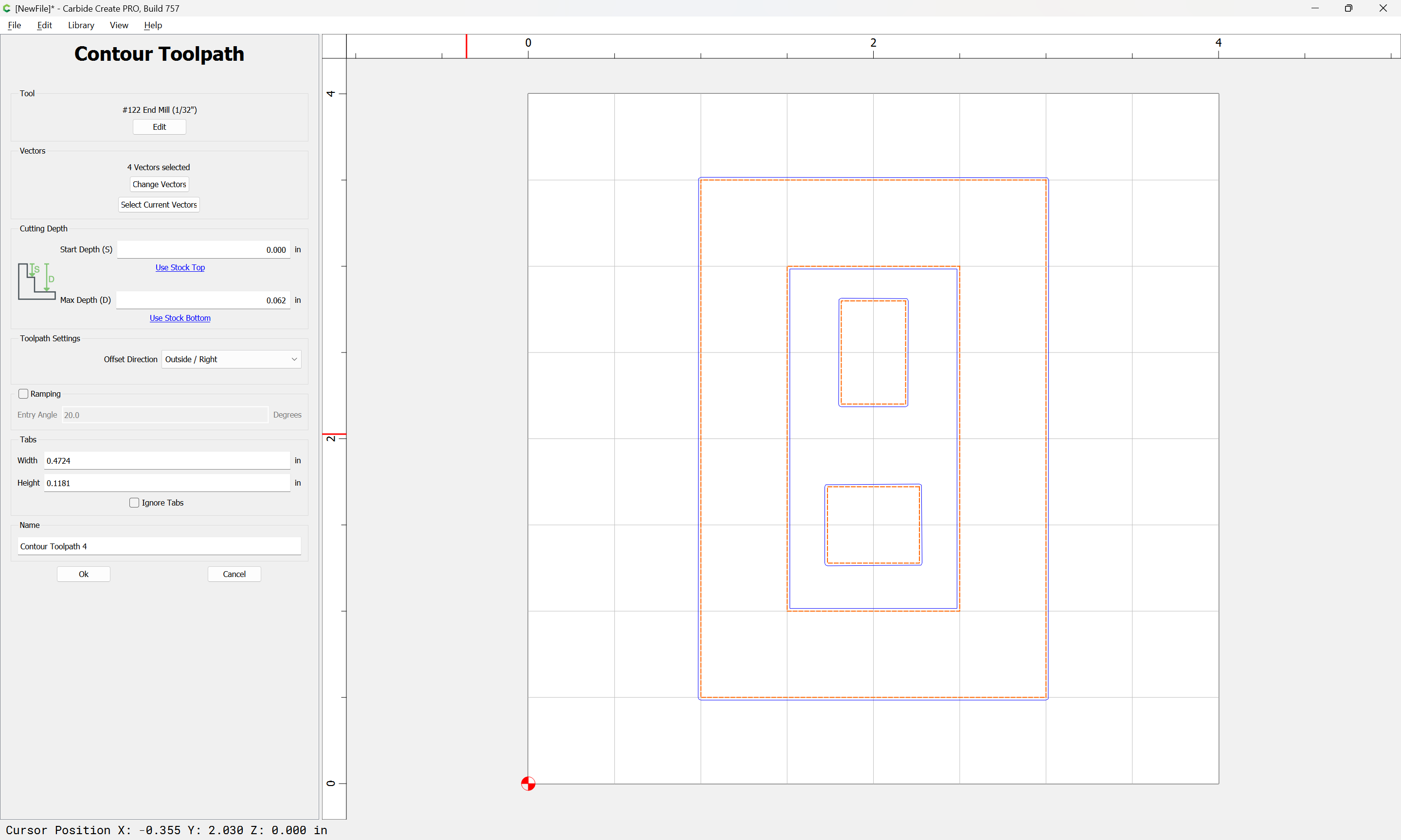
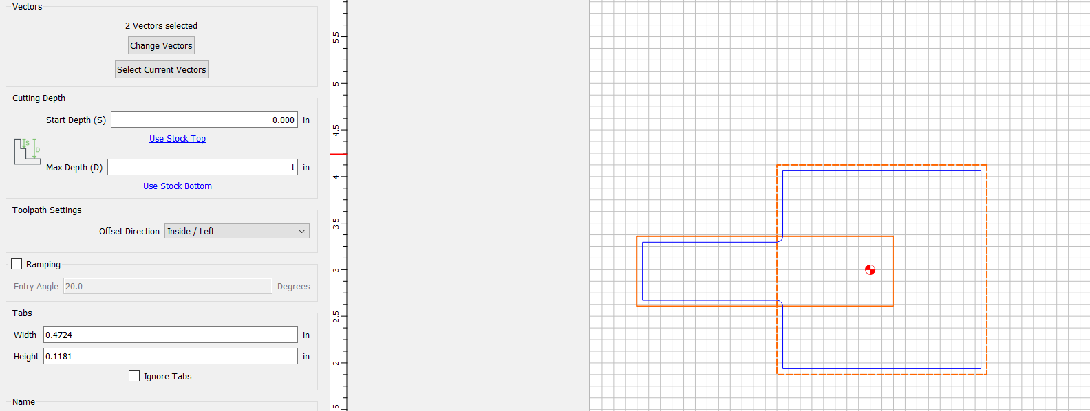
That vector is part of another group of multiple shapes. You can see the blue line indicating that it had an associated contour already. The inside rectangles are part of a group that have Outside contours, but they show that there’s an Inside cut
OK…so this might shed some light on what’s going on…
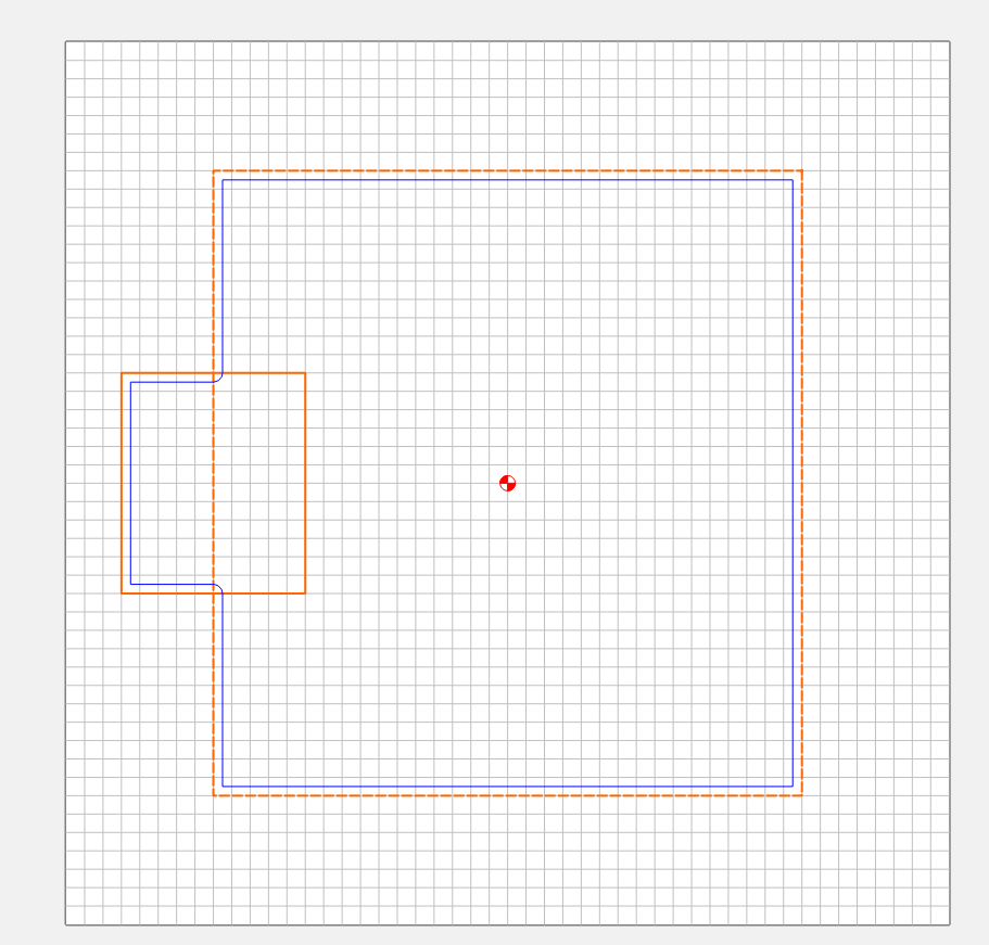
It seems that the selected vectors are not treated as a group of individual vectors, but rather as a union of the vectors that are selected…because overlapping the vectors, selecting them and applying a contour gets this:
which shows them being treated as though they were welded first…
Is that what’s supposed to happen?
[EDIT] If that’s what’s supposed to happen, then my “findings” are moot. The only way I can see of getting the internal elements to be treated independently, is to apply separate toolpaths to them, so that they don’t interact with any other vectors.
Nested parts are supposed to take said nesting into consideration.
Overlapping shouldn’t be used with toolpaths — it’s potentially confusing to the algorithms, but if a given geometry in a given file assigned a particular toolpath works, then it should work for that file when opened in that version as indicated by the 3D preview so long as nothing is moved/changed.
That said, this has implications to the strategy of using layers to organize your toolpath cuts. If you add a vector to a layer expecting it to be cut a certain way (e.g., this layer cuts “contour inside”) - you can’t rely on it unless you see where your vector lands in relationship to the other vectors on that layer. That could be quite unpredictable.
Kind of another reason to not use layer-based toolpaths, IMO.
The big thing is, what one sees in the 3D preview is what will be cut, so if you get a result you like, it should work so long as nothing (geometry, Carbide Create/Motion version) are changed.
I find layer-based toolpaths great for template-based work — if we could just get colour-co-ordinated layer assignment on import (which was preserved on export) I’d be that much closer to having a nice automation workflow.
Those images look to be how I’d expect such toolpaths to work, and they would cause the least confusion to typical users judging by how folks interact with the program on tech support.
Best of course would be to not use/have overlapping paths.
Just curious…because, clearly, I’m not one of those folks - but why would you expect a different behavior from no offset? I mean, the shape is the shape, I’m just telling CC to run the bit on one side of the line or the other (or on it)…so why would I expect a different line to be used based on that offset setting?
My use case was to create a “hole” in my piece of a particular size. The hole size desired was half the diameter of the bit smaller than the vector…so I wanted the bit to split the line - all the way around the perimeter…only, it didn’t. “Inside” would leave a hole too small…“Outside”, too large. “No Offset” would be ‘just right’…Goldilocks was quite disappointed.
Mind you, it was not so hard to recover from (I actually just welded the shapes together and did a no-offset)…but what was logical to me was that I had a pair of vectors that I wanted to cut…it’s one set of vectored lines that’s being cut - the parameter is only changing where, relative to the lines of the vector it gets cut — it seems strange that the left of the line/right of the line /on the line setting is referencing different parts of the vector.
Your statement about “Perimeter” makes me think…if the perimeter is what is cut, shouldn’t the setting imply: “Outside the perimeter”, “Inside the perimeter”, “On the Perimeter” Why would the setting change what’s being cut.
Then why does it default to perimeters when it’s going outside or inside? Why not cut to the outside of every vector regardless of the overlap?
The point is, it’s different based on a setting that shouldn’t be impacting which vectors are being cut. The behavior of “welding” the vectors to create a perimeter is inconsistent - or faulty…one or the other.