I guess I don’t understand why this fails. I have a puzzle piece that I want to cut several copies. I’m trying to cut the pieces for the puzzle box in the attached. I used an 1/8 inch bit.
I read something about cutting outside on one part and inside on the other part. But if I understand this then my part needs to be cut outside for the male sections and inside for the female sections I think. Is it possible to cut these pieces.

HeartPuzzle.c2d (21.2 KB)
First thing I would check is that your machine is properly calibrated and that there is no play in the axes.
After that I would say you probably need to take a spring pass or two on these parts if you are using an 1/8th in endmill. They are not the most rigid so they will deflect. Taking a second pass with the same settings will more of the material that would have been missed otherwise.
Also remember that different species of wood expand and contract at different rates based of humidity. So if you machine these parts over the course of several weeks it is very possible they will not fix.
All pieces need to be cut w/ an outside profile.
Inside profile would only be used for making a pocket to put the pieces into.
The exception would be when cutting out a puzzle w/ a tool w/ a thin enough kerf that along the contour can be cut out.
For calibration see:
For more information on cutting out puzzle pieces see:
I did cut the two test pieces from two different types of wood within an hour. The sizes of the pieces seem to be correct. But the male and female parts don’t fit.
PS I have had no problems cutting other projects.
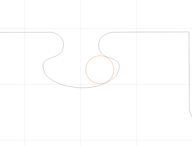
If the file you uploaded is to scale, you might need a smaller endmill.
Here’s a 1/8" diameter circle next to the concave part of the puzzle piece from that file:
It doesn’t look like it fits very well.
Another thing to consider, in addition to tool deflection & material surface finish, is the fact that you don’t want to have to wrestle the pieces together. i.e. you don’t want a “press fit”.
One way to get a “slip fit” is to LIE to the CAD system (Carbide Create, etc…). If you’re using a 1/8" cutter, set your cutter diameter in the tool library to 0.123". Now your toolpath is 0.002" closer to the profile, and will remove a little extra material. 0.002" doesn’t sound like much, but it gets doubled because the mating side also has 0.002" extra removed.
Thanks I used a 1/16 bit and I get a tight fit.m Also I found that the horizontal size was slightly smaller that the horizontal size. So I fixed the issue.
How does one change the size of the tool? When I select the tool the edit is not allowed.
PS wish I could find the plans for this project. Only place I found it was a site that wanted 67.00 to join and get 16,000 plans.
Tools can only be edited if they are in a User Library — you’ll need to make one or duplicate an existing one.
I spent a fair amount of time searching for where the tool data base is located. Most results said in c:/users/xxx/appdata/local/carbide 3d/tools. But nothing is in that directory. I finally found what I think is the tools database. It is a file called ccpro.db. It is not an sq database.
But if you use the duplicate library you can get that information stored in the tools folder in csv format.
Forgive me, yes the tool libraries are buried in the code somewhere. You have to create your own.
I created a tool called “MILL_0.375” and another called “MILL_0.385” to leave 0.005" finish stock.
I use the actual 3/8" mill to cut on the machine. And when CM asks me to change tools, I just hit “Resume”.
I found puzzle piece svgs online for free. (I think here: Puzzle template | Free SVG)
You could import one of those, then overlay the heart shape & trim. You would then have to separate each shape to cut them individually. I used it to just contour a vee-bit to make it look like a puzzle without separate pieces.
Thanks. I have a puzzle.svg file. I can’t use the vee bit since the puzzle pieces are from different woods.
This topic was automatically closed 30 days after the last reply. New replies are no longer allowed.
