Hello all. I’m back. Getting close to start cutting.
My question is once material is in place on the waste board and i’m ready to go, where do I set my starting position for this? WCS
Do i do it in front left corner?
It doesn’t really matter as long as the WCS origin you set in Fusion 360 is the same as the location you set your XYZ zero on your actual stock on the machine’s wasteboard.
1 Like
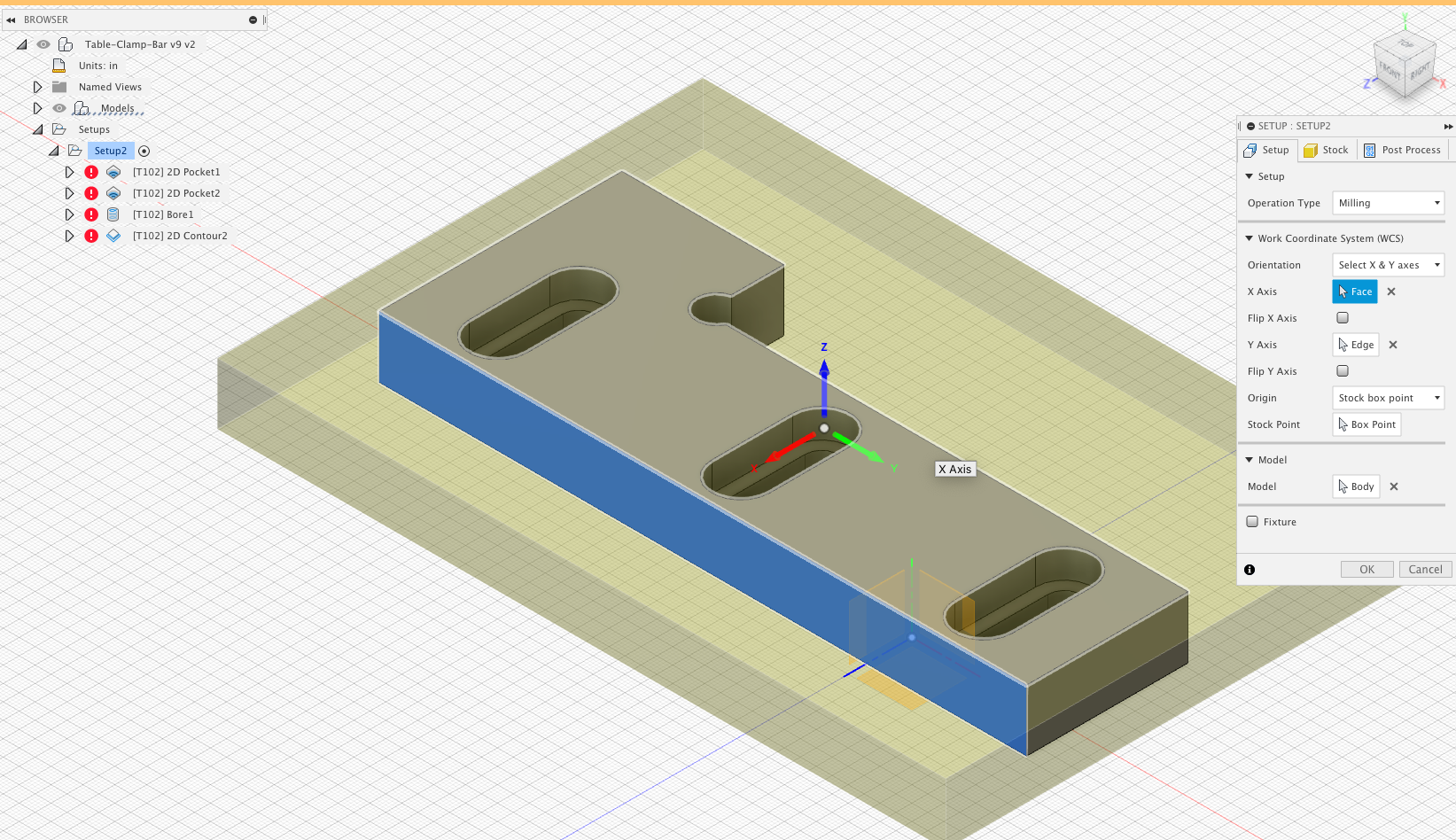
You have the origin on the lower left, but your axis are pointing the opposite of what you want.
Nomad axis looks like this (shooting from the hip) so you want the arrows pointing on the WCS like they are on the machine. Until I had it straight in my head I usually run the program on the Nomad with Z-axis zero set up high, cutting air until I was sure I had it right.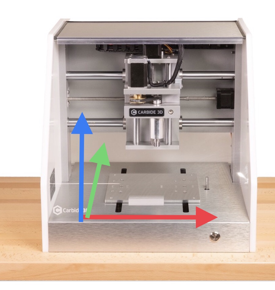
2 Likes
I was about to make that same comment, and if someone figures out a reliable way to tell Fusion360 to orient the axes in the desired way without going through a few maddening iterations in the user interface, I would like to know 
Click the little arrows.
5 Likes
![]()
so THAT’s what I was missing, thanks !
1 Like
Thank you Phil. Good catch. I actually watched a video about this few minutes ago
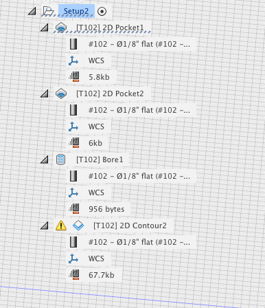
Ok got everything oriented, did generate and got this warning:
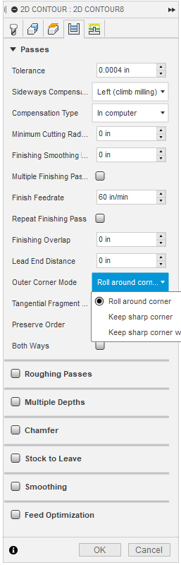
Warning: Smoothing is not applied for keep sharp corners mode.
Warning: Smoothing is not applied for keep sharp corners mode.
Generation completed with 2 warning(s) in 457.2ms.
Anything that jumps out as wrong? warning safe to ignore?
Here is what it looks like now. Also cut stock closer as well.
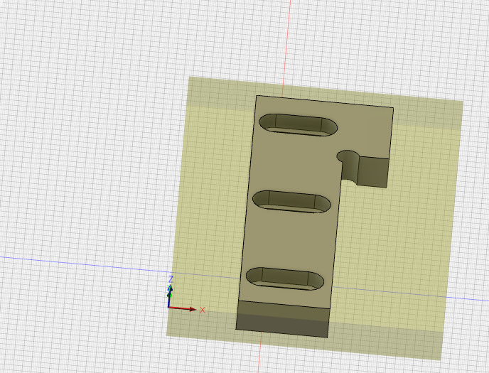
WCS orientation looks good. What toolpath(s) are you using? 3D contour?
Here is what I got so far
Do you have keep sharp corners enabled and smoothing enabled? If so fusion may only want one or the other. Or the smoothing tolerance may be too big. Try either disabling smoothing or tightening the tolerance on it or disabling sharp corner mode. Is the dog bone relief you have in that corner exactly 1/8? If so that could also cause it as your endmill is 1/8". You could try making the relief hole in the corner something like .130".
2 Likes
I’m back. Just tried cutting and it was cutting in air
i would guess about 10mm above where it was suppose to
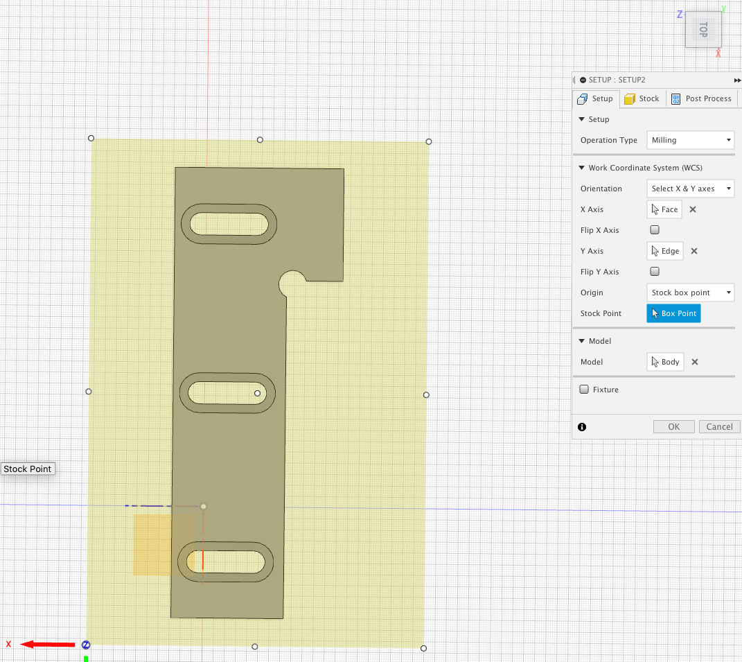
I set the zero points on front left corner. circled in red and used paper to set z
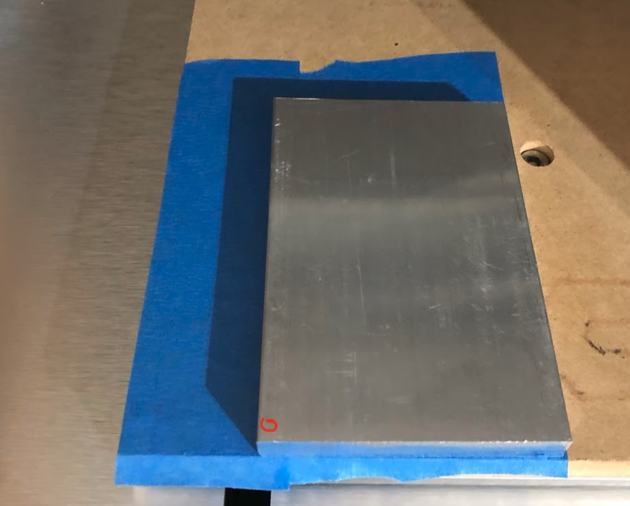
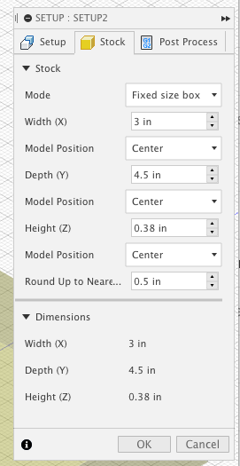
Here is how its setup in fusion
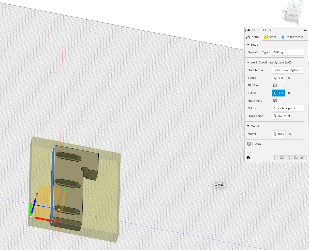
Any ideas what I missed?
Thank you
how do the toolpath and toolpath simulation/preview look like in Fusion ?
You should check your generated g-code with a g-code viewer: if the toolpath is “in the air” is the g-code preview, you’ll know it’s a design issue in the CAM in Fusion, and if if looks correct, you’ll know it is most likely a problem in your zeroing procedure on the machine somehow
Simulation in fusion looks good. Doesn’t look like its doing it in the air. ncviewer simulation looks good as well.
Hmm.
I did the following:
Did the homing sequence then moved the head to the front left corner, lowered the z until it grabbed the paper. then clicked zero X, zero Y zero Z and started the program.
Here is the file I’m using.
table-clamp.nc (60.8 KB)
Getting close!!! I assure you 10mm high is a vastly better outcome than 10mm low! WCS looks good to me from the screenshot. I know a couple times in the moment I have actually forgotten to click the zero Z button and just exited back out of that screen. Did you go and jog back to 0,0,0 (as indicated in Carbide Motion) after the failure to confirm they were set where you thought they were?
1 Like
yes 10mm above is definitely better
I did set them and when i go to Rapid position and click current x and y it takes me to the correct coordinates. Clicking z takes me above starting point exactly 6mm. I jogged down 6mm on the z and it grabs the paper.
Hrmmm. Thats interesting - would almost think Fusion is putting 0,0,0 at the bottom of the stock instead of the top - but it doesn’t look look like it. When you run the simulation in fusion with the stock visible, what does it look like?
looks good. here is a screencast
here is a video of the coordinates in carbide motion.
Ah ok. It will start high because you are helixing (spiralling) in. That being said it looks like your first 2D pocket 1 toolpath doesn’t actually penetrate the material. You should see the end mill going down into the stock and being cut away on the simulation. Some odd bumps on 2D pocket 2 at the back there but cant see the reason.