Can I reference tools off something other than bitsetter? Something like this?
Use case:
Load mini Haimer
Measure manually
Set WCS
Load cutting tool
Measure manually
Run job multiple times.
Can I reference tools off something other than bitsetter? Something like this?
Use case:
Load mini Haimer
Measure manually
Set WCS
Load cutting tool
Measure manually
Run job multiple times.
Yes, but as noted, one has to set the zero manually using the tool, and it’s the responsibility of the operator not to plunge it so fast as to damage the tool.
I just got my 30 degree but from IDC replaced exactly because I fee like the plunge and pressure from the bitsetter damaged the tip. I recently replaced the innards on my bitsetter and the spring seems pretty stiff.
Is there a material I can add to the top of the bitsetter that would be more gentle and not impact accuracy (too much). Wood, HDPE, whatever?
I currently have the bitsetter disabled and set the tool to the top of my work. I don’t see a place where a tool measurement can be manually jogged and set in this setup.
If I enable the bitsetter I would assume it would move to a location and move in z until a signal and set a tool length. I’m asking to do similar but manually.
After my post I looked at Gsender and it appears there is a M6 scenario that can be selected that seems like what I want. I’ve cut 2 parts with my machine and not really ready to jump to a different sender yet.
It would have to be a totally manual process.
Output toolpaths separately by tool, with no tool changes.
Setup job
1st tool - Set zero on job
Measure tool 1. Note the Z position when your indicator is at it’s index point.
Load first file & Cut first path
Change tool
Measure tool 2.
Type in the noted Z value from the 1st tool.
Load file 2 & cut
Anything which yields will add the inconsistency of that yielding to the accumulated error in measurement of the homing system and so forth.
Right, but that initial plunge seems pretty aggressive to me though. What info slip something between for the initial plunge and then pull it out for the slower plunge?
The initial fast plunge is to find the BitSetter, the second slow probe is to set the length offset more accurately (the error of the probe is related to how quickly it is moving/how large the steps are at that given moment when the circuit is closed).
Here is what i was referencing in gSender. #4 seemed promising, but could be different than what i was thinking.
You’ll understand your machine more when you use different senders. You’ll make mistakes, but they’ll be yours.
Neil,
Do you understand what I’m trying to do? And a way to do it?
Basically I want to set a tool offset, use that to set a work offset, then when I change tools, just change the tool offset.
Maybe… essentially the same thing the Bitsetter does, but using the manual probe?
If that’s it, I’d
Isn’t there a tool offset when using the bit setter?
With Motion, yes (I think).
You can set a dynamic tool length offset with G43.1, but if you’re doing this manually that seems like some extra and unnecessary work. The main reason I went away from dynamic TLO is mainly because they are not persistent across power cycles. I found things simpler by saying "If this thing is located at Z10.245mm with this endmill, then I just make the Z 10.245mm with the next endmill at the same spot. It’s the same as setting Z-zero in the same spot rather than calculating the difference in length of the endmills. If you have an ATC and the difference is known ahead of time, then I think the TLO makes sense but then there is no need to probe.
GRBL has a single “TLO” register. It’s stored on EEprom, so I assumed it was persistent (until erased)??
However, I have no idea if using the bitsetter uses the $TLO memory in the controller.
It would be nice to see the toolchange macro in CM to understand what it’s doing. And if it’s not using the $TLO register, understand how to use it. I haven’t found anything online yet that explains it.
It is not stored. It behaves like G92 and clears when the controller is reset (soft resets as well).
I think the rationale was that resets are generally because it’s a new session or something bad happened.
Neil,
My thoughts on workflow.
Load Spindle Probe
Jog to Reference Plane of manual table probe. Spindle Probe reads zero.
Set Z
Jog to Part
Zero Spindle Probe on Top of Part
(Not Sure how to Set this point) Record and G10?
Remove Spindle Probe
Install First Cutting Tool
Touch off on Manual Table Probe
Set Z Zero
Run Program
M6
Remove First Cutting Tool
Install Second Cutting Tool
Touch off on manual table probe
set z zero
Resume Program
M6
Etc.
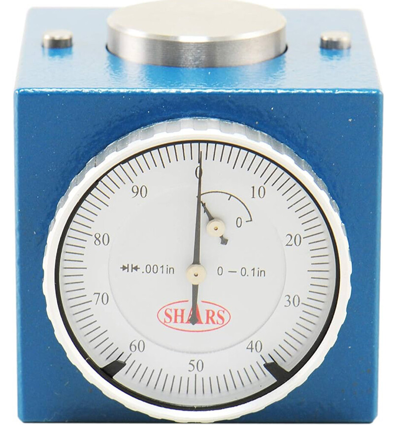
Set Z to what? You have no reference at this point. Also, be careful using zero on the tool length setter… There’s a fine line between just making contact and not making contact at all.
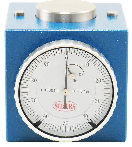
The small pads to the left and right of the larger pad are Zero. The center one is attached to dial.
I was saying since the spindle probe is also a indicator, it needs to reference to a fixed point.
Right, but what are you going to set Z to when you touch on the manual tool offset thing?
I may be unclear on what you’re trying to do here.