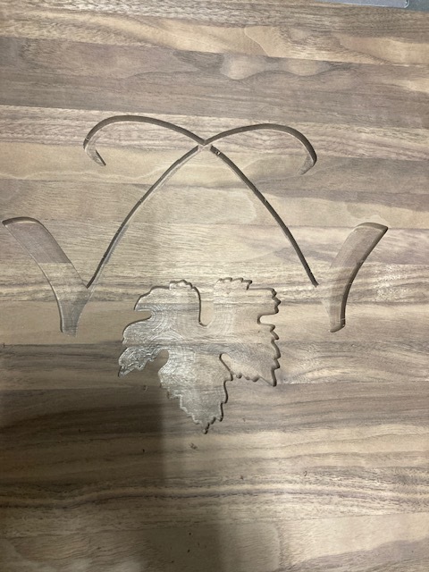
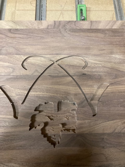
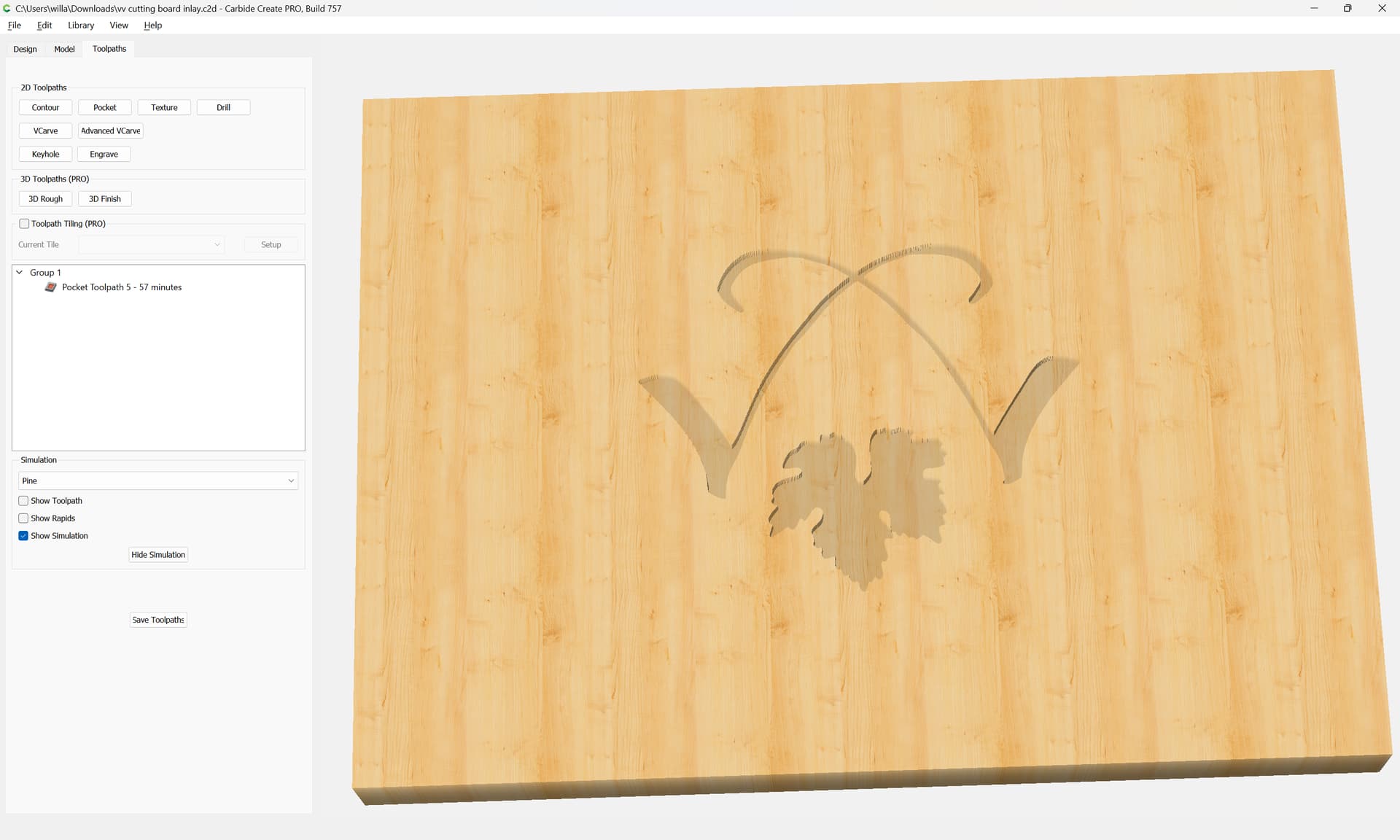
I have had my last two projects fail when it came time for repeatability. I don’t have pictures of the first project as I ripped from the confines of its hold-downs and proceeded to wing it down the street. Attached are pictures of some perfectly good walnut which I ruined by cutting it into strips just to glue it back together. I also attached the Carbide file.
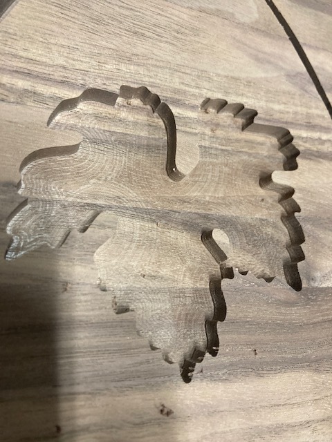
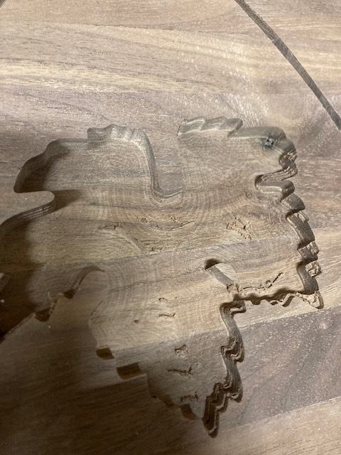
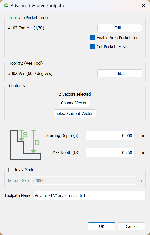
The first photos show a nice pocket ready for inlay. The second pictures show that somehow during the milling process the machine forgot where the starting point was. It sort of wandered for lack of a better term.
after the first failed project I went through the machine, cleaned everything and made sure the belts were properly tensioned. I’m sort of at a loss as to what to try next. Thanks in advance everyone vv cutting board inlay.c2d (828 KB)
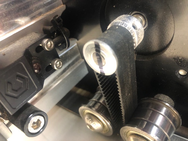
I always recommend to check the v wheels to make sure they’re tight and then the pulleys that attach to the stepper motor. I’ve seen many set screws back out of the pulleys which allows the flat to turn and loose steps. I replaced mine with shcs for a little more bite on that shaft.
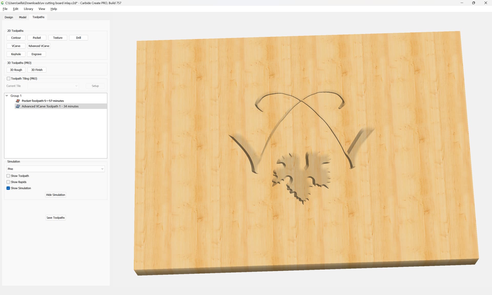
but you’re using a tiny, 1/16" tool and cutting to exactly the depth of the flute length, 0.25" — and your stepover is the default of half the tool diameter — if you have a BitSetter use an Advanced V carving instead:
Or, use REST machining starting w/ a larger tool if you have Carbide Create Pro.
Or, use a cleanup path with a different stepover.
For checking the machine mechanically, Per the machine operating checklist: Machine operating checklist , the basic points of adjustment for a machine are:
(for belt drive machines) Pulley set screws — verify that these are in-place and secure — be sure to check all axes/pulleys (including Z on machines w/ belt-drive Z-axis, for an HDZ, check both coupler screws).
(for the SO3/4, X- and Y-axes, and the belt-drive Z-axis on Launch and summer 2016 SO3s) V wheels / eccentric nuts (per assembly instructions)
(for HDZs, and HDMs, and SO5 Pros) check that couplers between the motor and ball screw are secure, for the SO5 check that the DAC which transfers the rotary motion of the ball screw to linear machine motion is secure on the carriage/gantry
(for belt drive machines) Belt tension (see the relevant step in your instruction manual, Note that the X-axis motor is held in place on standoffs and if those bolts are loose this can cause belt tension issues. Also, belt tension for the Y-axis stepper motors needs to be even/equivalent on each side — a significant difference can cause skipping on one side eventually resulting in lost steps on both. Measuring belt tension, squaring and calibration
Naturally, this assumes that all the wiring is in good condition and all connectors secure per the Machine Operating Checklist. Verify that all wiring is in good condition and all connectors are secure, and that all wiring leading into connectors are properly in place and are secured so that the wiring leading into and away from connectors will not shift.
A good video overview on setup:
Tramming the Z-Plus:
Ensure that all screws are in place and secure, esp. on the linear rails on a Pro.
Thanks for the reply Will. I have the Pro XXL and I think I have narrowed my issue down to the set screws for the right side motor sprocket. Currently there aren’t any and it doesn’t look like the left side. Can I purchase these set screws? Also, how do I access the Z axis motor to check the set screws there?
The set screws are standard metric M3 grub screws, ~4.75mm o.a.l. — that said, some folks will replace them w/ M3 SHCSs of a suitable length (8–10mm) since that allows using a longer hex key for more leverage when tightening.
If you can’t find suitable hardware let us know at support@carbide3d.com and we’ll work out getting some to you.