So far, my only issue with the HDM has been squaring the gantry before the machine is turned on and it’s much more difficult to do than a belt drive because of the ballscrew resistance.
Do you mean having two homing switches for the Y-axis and driving the two Y-axis motors independently to arrive at a consistent positioning (which one would adjust the switches to be square)?
Wouldn’t it be a similar system to touching off tools such that you may enter the first contacts quicker and then touch both inductive sensors a second time to make sure the homing is square on both sides with the two sensors.
In your time with the machine how far out of square does it get if not pushed against the frame?
I don’t think with my disability I would be able to push the HDM gantry so this is a concern to me.
I don’t believe Grbl supports auto-squaring (aka independent homing sensors for paired axes).
It has been a nice feature when I moved to a different controller/hardware (Mach4, UCCNC, etc.) ![]()
with UCCNC, you can tie it with homing back off settings per motor axis, so you don’t have to fiddle with sensor alignment to get the X gantry square/perpendicular with Y.
@WillAdams yes dual Y axis homing switches. I’m not sure if you would need to adjust them if they are both placed like they are now.
@Able its not much but more for peace of mind for repeatability after a crash/rehome.
@DanStory ive seen that grbl 1.1H has the ability but haven’t heard of many people (in any machine) using it. That adjust-ability in UCCNC sound nice
Did not realize it did, but looks like it is a build flag to support it and removes, moves and shares inputs/outputs across the limited GPIO.
Edit: not sure if Carbide3D’s compiled version has that flag enabled or just shares a single axis step/dir output
1 Like
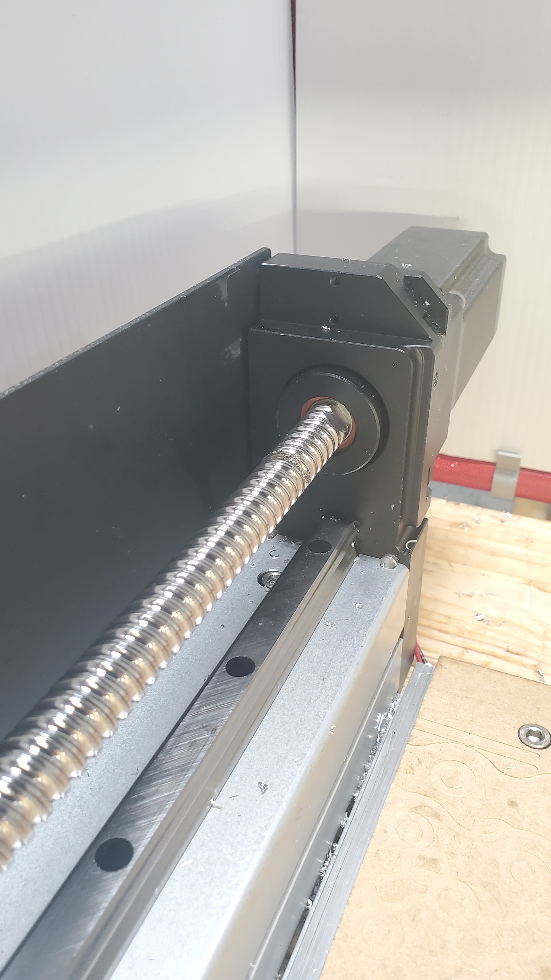
I think your ballscrew needs some fish to go with those chips ![]()
Got any more pics of the HDM undressed without the covers and panels on?
1 Like
@Luke responded this when the machine was announced:
- It’s single limit switch - we did play with 2 but it was actually really problematic. Whilst each limit switch is highly repeatable each limit switch could have a slightly different trigger point. Thus actually trying to square an axis basis on a limit switch is really tricky - I have squared mine mechanically and that has done the job.
2 Likes
Optical switches would fix this. Capacitive and mechanical switched do have a larger tolerance.
The controller would need to support independent Ys. Does the warthog support that?
1 Like
I was told the same thing but…its not something I’ve only had to do once.
I understand that switches can have a different activation point. Let’s say we have to shim them. Everything would be consistent from that point on.
Consistent is the key word
Setting by hand is not consistent and the best I’ve been able to get is the Y rails within 0.003" of each other (up to 0.020"). I’ve had crashes and chip build up cause independent Y stepper skipping. I should be able to fix the problem and rehome the machine but with only one stepper being homed, I have to manually reset both Y steppers.
My request of dual homing still stands.
It’s not a “deal breaker” and the machine still performs very very well. Most people probably won’t notice or have the same issues I’ve had. The last big aluminum project cut over 10 pounds, hitting well over 3 cubic inches mrr in roughing. The only issue (except for wanting the 2 2kw option) I ran into was tram error due to the y steppers.
8 Likes
It looks like it’s possible here. I’m not sure what’s the difference is between grblHAL and the fork C3D uses.
Quite a bit.
grblHAL is the evolution of Grbl that requires a more powerful MCU on the CNC controller.
Regardless, auto squaring is available on regular Grbl, but only when the second Y-axis motor is receiving separate Step and Direction signals. I don’t know anything about the Warthog controller, but previous Carbide boards would not be capable of doing this.
Maybe @Jorge, @wmoy, or @Luke could chime in on the details of the new electronics.
Interestingly, it appears that on the more industrial CNC platforms you don’t fine adjust the sensor position, you simply tell the controller how many steps to back off the sensor activation point. So if your sensors are repeatable enough to be useful, you can measure up and back off by different numbers of steps L&R to be square.
The current controller does not support de-coupled Y-axis movement so dual switches would be pointless without some hacky multiplexer-esque system to selectively enable Y+/Y- drivers based on sensor feedback… blah blah blah.
For the level of precision that’s reasonable to expect in a $4-figure machine, I’d say maybe just turn the Y-motor couplers by hand to “soft-crash” the gantry against the back of the machine (assuming the frame is square). Then power on the machine, let it back-off the sensor (might take two “initialize” cycles), and then use the machine as normal.
If you hard-crash the machine and lost steps, maybe do this again. Otherwise just “re-square” the gantry once or twice a year.
If the frame isn’t square (within the level of precision of your liking), just use a shim on the endplate to reference the gantry against. Unbolting the frame/y-rails is just more trouble than it’s worth and could lead to more problems down the line. But you’d need a really big granite square or something to make this level of calibration worthwhile.
TLDR, no this is not possible, but for the vast majority of people it’s also not going to result in any meaningful improvements in QOL. Just go forth and cut things. It’ll come out fine!
5 Likes
I “soft crash” mine to the front. I noticed that if I did the back, one side moved slightly after I banked. Using the front was more consistent on mine.
2 Likes
Solution, even if its the one we didn’t want to hear lol.
Ok, so lets talk about the best way to manually reset the gantry. The Y stepper couplers are completely covered and not accessible so you have to turn the ballcrews by hand or using quite a bit of force to pull the gantry forwards.
What do you think bout modifying the Y travel limits and making a Macro to “crash” or push the machine up against the front at a low feed speed, then rehome after?
1 Like
In all likelihood that would probably be okay but not something I’d want to recommend. If you take off the inside covers you should be able to rotate the ball screw by hand.
1 Like