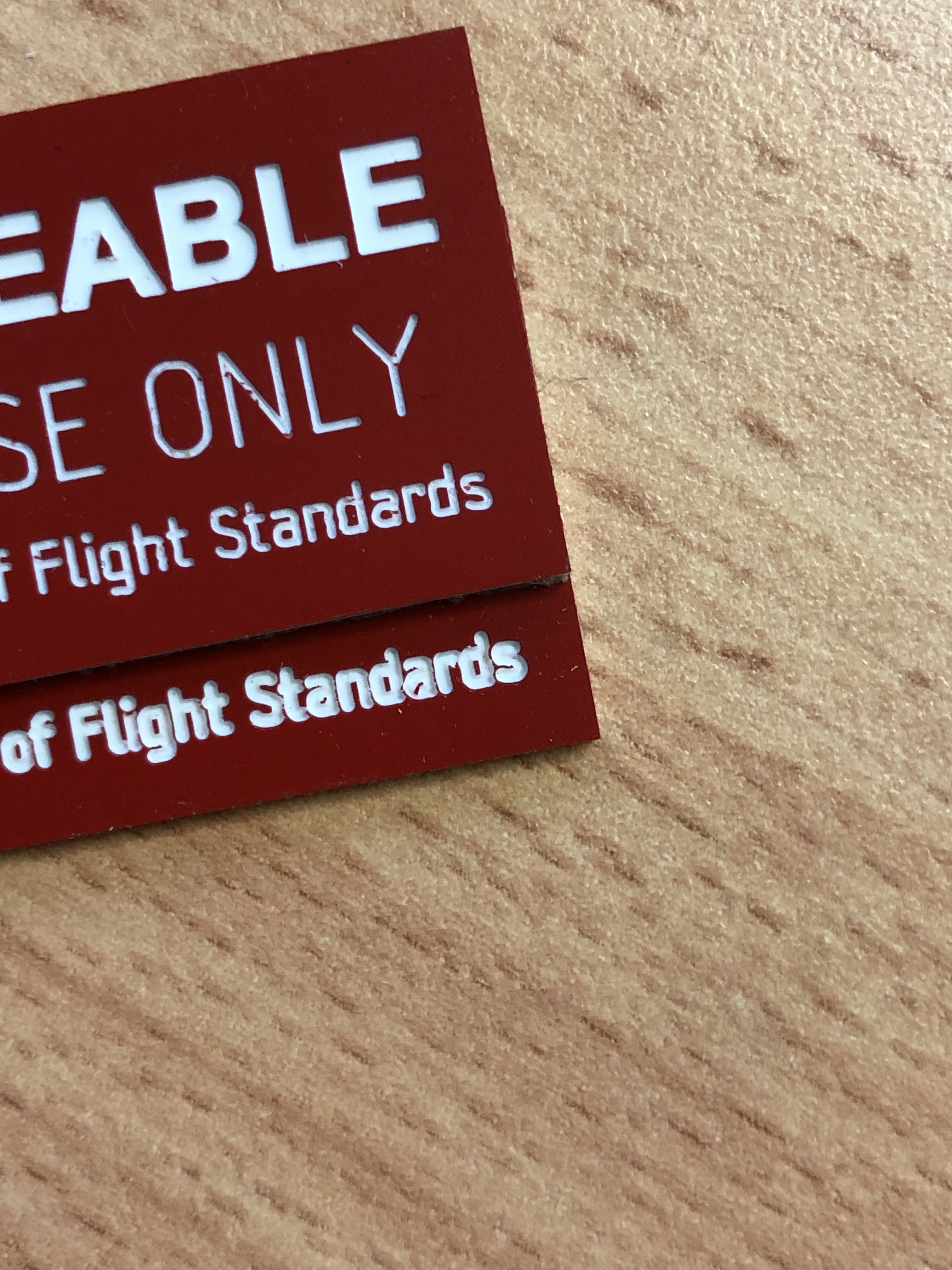
So I’ve been having trouble for some time getting an even cut making acrylic placards. I’ve squared the machine (XXL) using different methods, trammed the spindle probably 5 times and resurfaced just before running a job and the problem persists. Some labels are perfect, some come out with the text looking bold and letters touching each other and others the bit doesn’t even touch the stock.
I thought it might be a material problem because it has adhesive applied to the underside but I got the same results using material with no adhesive backing.
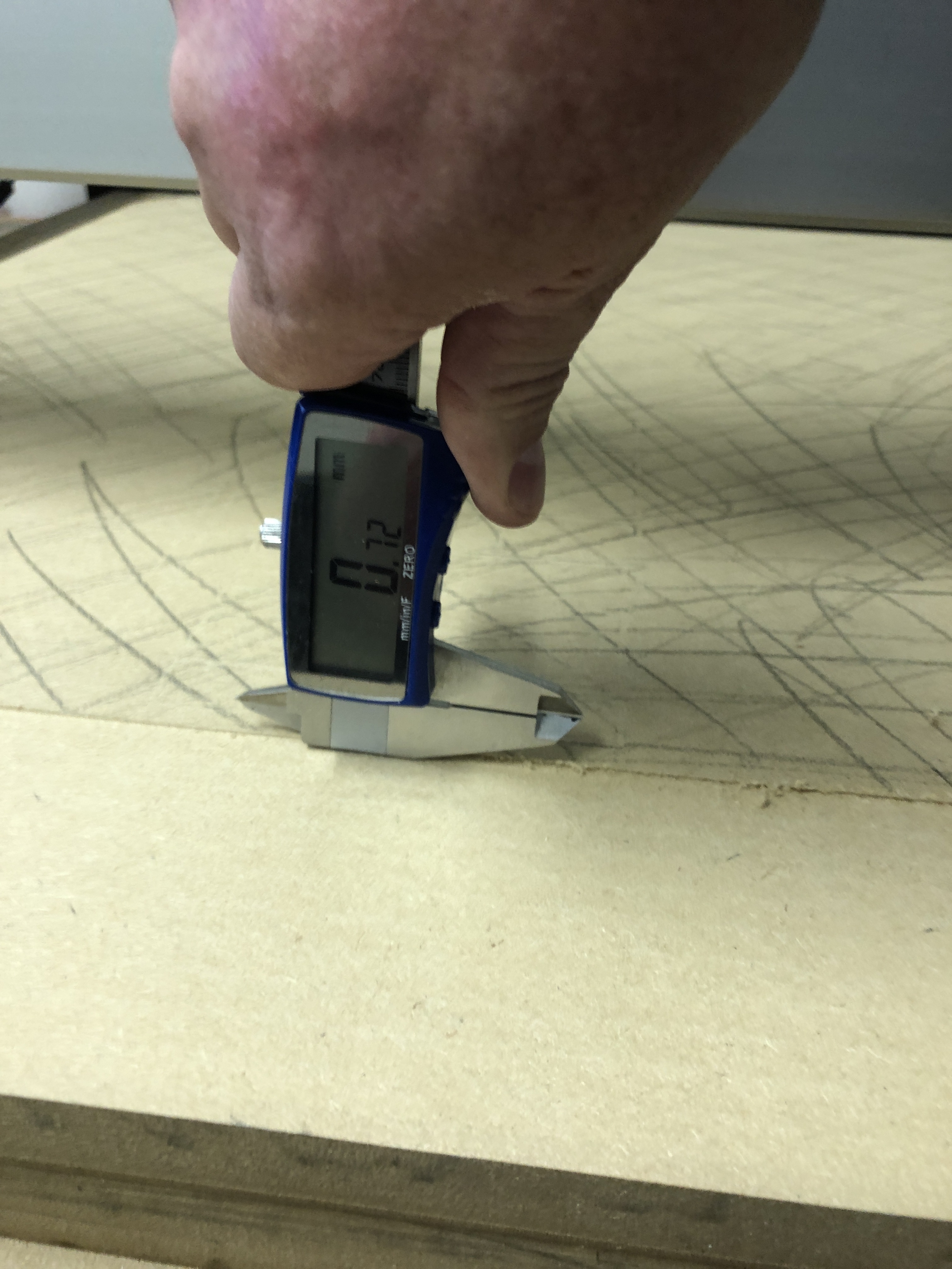
Today I mounted a dial indicator to the Z axis backplate and ran it across the freshly resurfaced vacuum wasteboard without turning of the vacuum and saw a random change in height of up to 0.2 mm (0.008")
Some of my text is only 2.5mm high and I usually have a 0.2mm DOC which gives me a nice, clean single line text.
Oh and I have thoroughly cleaned the tracks and v wheels on the X and Ys
At this point the machine is useless for cutting these labels/placards but there must be a way. I mean this is how signs were made before laser, right?
Has anyone experienced this and what was the fix?
I’m using a 1.5kW Chinese spindle
MDF vacuum wasteboard
Shapeoko 3 XXL
Do you have a picture of how the cut looks in various parts of the work area? (I understood your statement about different labels coming out differently as meaning that depending on where they are located on the work area, they are cut deeper, or shallower than expected)
Do you have any sag in the middle of the wasteboard? Cutting fractions of a mm deep over the large work area of an XXL is a worst case scenario and may require some tuning/support of the bed to minimize any residual bending (that would otherwise hardly be noticeable for most jobs). Resurfacing may not suffice if the bed sags (even just a little…0.2mm is not much), since the sag will depend on the weight on the wasteboard so the bed will flex slightly differently with and without stock loaded.
I’m sure the XXL owners will chime in with good tips.
The other, complementary approaches for getting perfect uniforms engraving depths over large areas is to leverage:
spring-loaded tools, which compensate subtle variations in depths. Diamond-drag bits are the prime examples, but I remember reading (here) about a spring-loaded holder for tiny vbits, for lettering.
surface-mapping (“bed leveling”) software which utilizes a physical probe to map out the precise variations in the surface before running the cut, and then adjust the G-code accordingly, compensating for any depth variations. This is however only supported on a small number of alternate G-code senders (bCNC does it, CNCjs may be able to support it.
Folks who do PCB milling tend to use that surface mapping technique, because they need to be within that kind of 0.1mm accuracy over a large-ish area.
What tools are you using for cutting these labels ?
I considered the sagging bed but that doesn’t explain the randomness of where the high and low points are and if I resurface with a sagging bed, wouldn’t the resurfacing still make it all as level as the x and y axis?
I haven’t checked how straight those rails are though. I just took it for granted that C3D would provide accurate product.
But again, if the rails were slightly bent, the resurface should still be the same distance from the spindle?
Which tools are you using to cut with, and which Z-unit do you have?
I would think that resurfacing the waste board and tramming would be good enough since it doesn’t take much to cut plastic (ie bed deflection from down force). If I read correctly, you’re seeing .008” of variance on your waste board?
It would also be good to share your work holding strategy…
It looks like there might be something else going on too since some of your text look a little wavy or that might be my eyes playing tricks.
Also, silly question: how sure are you that your stock material is perfectly flat to begin with ?
Sometimes stock looks flat but isn’t quite. For the sake of testing only, you could run a light surfacing pass over the whole stock, say 0.4mm deep, and then re-zero on the freshly surfaced stock, and run your job then. I would not be surprised if everything turns out fine then. Of course this would ruin a sheet of your acrylic, but you would then know that it’s the stock, not the machine.
My XXL was sagging in the middle. I put a 3/4 piece of plywood right in the middle. If you decide to level your spoil board make squiggle pencil marks all over the surface. Then cut the surface down until the pencil lines disappear. This pencil procedure makes sure you have surfaced the whole surface. Just by looking you cannot really tell if the entire surface has been cut.
Currently I am working on making a torsion box for my Shapeoko XXL to sit on. When finished in a few days I will remove the leveling feet on the Shapeoko and use a piece of rigid foam to set the machine on. I want a level place to set my machine and the foam gives even support all over the bottom and may or may not absorb sound. My goal is not about sound but about a level top and a solid base for my machine to set on.
Hi Brian,
I’m using a 1/4” 2 flute straight edge router bit to surface the bed.
Yes I’m seeing 0.008-0.010 of height difference even right after resurfacing.
I made a vacuum table out of mdf so the is my work holding method.
Oh and I have the Z plus with Chinese 1.5kw spindle
Hi Julian, unfortunately it’s the wasteboard that I cannot get flat. I’ll run a light resurface and then check that surface with a dial indicator right after resurfacing. Not even turning the vacuum holding off so the bed should be dead flat. But I’m still seeing these highs and lows in the board.
I’m attaching the dial indicator to the metal backplate of the Z plus and then using jog to move around the board
I have to ask (sorry if this is obvious), are your taking deep enough of a cut that you are positive that the whole surface actually got cut in all areas during that resurfacing pass? A neat trick is to use a pencil and draw squiggles all over the area to be resurfaced. If any of the strokes are still visible after the surfacing, you know for a fact that the cut was not deep enough.
I haven’t used a pencil Julian but I have observed many times the consistant burr while it’s running the toolpath. I am only cutting 0.1mm DOC as well So I might do a 0.5mm cut with pencil and see how that goes
I thought I saw that a few months ago. It was leaving a pattern in the surface of a job but I thought is might have just been the wood. I haven’t seen it with aluminium but I haven’t faced any aluminium larger than 100mm square so it was too small to tell.
I’m still having no luck resurfacing to get the table flat enough to successfully engrave my acrylic labels.
If anyone has any suggestions, please throw your thoughts this way.
I disassembled the Z axis, cleaned and lubricated everything. The spring was loaded as stiff as it could go so I backed it off half a turn this time but still with the same results.
Moving the Z axis up and down with a dial indicator attached, I can’t get it to move 0.025 up then down. For example, if I jog down to a random height, zero the dial indicator and jog up 0.025mm, the spindle only raises around 0.004.
Is there something in the Z axis that could be causing these resurfacing issues?
I’m almost done with this machine. Surely it shouldn’t be this difficult to rotary engrave labels consistently??
How large is your stock initially ? / How many of those labels are you cutting at once and do you still see some of them being cut at the proper depth and other being cut too deep/too shallow ?
Finally, can you tell us more about that “MDF vacuum table” or yours ? Any chance it might have inconsistent suction in places, and the problem is workholding? (Sorry, I’m shooting in the dark here to try and help)
What are you cutting the letters with? In the picture you shared of the label, it looks wavy like there’s something else going on mechanically too.
You might be better off going with a more stable material than MDF since you’re chasing thousandths of an inch. Are the high/low spots repeatable or random? This might help differentiate between something mechanical or varying in the MDF itself.
That’s not good, are you losing steps somehow? I can’t imagine that this is the case but is a 1.5 Kw spindle too heavy for the Z-plus?
What happens when you jog down 1” and try to jog back up the same distance?
That loss of distance (0.025 expected raise up but only seeing 0.004) when reversing direction is due to backlash. About 2 months ago I had a few posts on here trying to find a way to limit or minimize that loss of movement when reversing directions and I was told that was within spec for the z-axis…
You can minimize it if you always set your zero moving in the downward direction, as the zero will always be the zero if beyond the backlash threshold.