The subject of rounded corners has been posted several times and creating over lapping boxes, inserting a circle, and executing the Boolean function works fine for me. I have an existing design which was made with square corner and now the user wishes them rounded. I’ve tried creating a simple square and placing an over lapping square in the corner then adding the required circle, but I either end up with the piece I’m trying to remove, or a square with parts missing. Any step by step process for this operation, or is it even possible? -Henry
If I understand your need correctly, you might do this:
- create a square S with a size equal to the desired rounded angle radius
- create a circle C centered on one corner of this square, to another corner.
- boolean-subtract the circle from the square (S - C)
- use the remaining corner to align this new piece to the angle you want to round
- boolean-subtract this piece from the original piece to be rounded.

Yes. @Julien’s technique works.
Alternately, cut notch, then add a circle.
I believe if you’ll go through this tutorial:
Should get you to an understanding of the concepts involved. See Shapeoko CNC Router, Rigid, Accurate, Reliable, and Affordable for further reference information.
If not, let me know and we’ll work up something more specific.
Julien, I think my problem is understanding the Boolean options themselves. They appear to have both “green” and “black” segments in their icons. In your sketch, do I select the c and s creation? Selecting two objects apparently triggers the Boolean functions. The Boolean-subtract I found by running my mouse pointer over those symbols and reading the respected function, then it’s not intuitive which part of the Boolean function I need to click on to get the desired result. But your sketch is clearer to me on steps needed. So in the first step you create the desired shape that will be “subtracted” Step two is positioning that piece on my corner. Step three is subtracting the shape from the corner. So for a rounded corner in this example, you have to use the Boolean-subtract twice before getting the final product. Thank You! Also that you Will as always.
Success, but I also learned another needed operation. When I positioned the piece over my corner, I was sometimes leaving a portion of the object hanging in space. Even though the “snap to grid” option was selected I found that merely placing the item on the corner wasn’t sufficient. I had to grab the part by the 90 degree corner “Node”, and everything fell into place. Yea !!! This old dog is starting to wake up. Thanks again. -Henry
2 Likes
Good to hear. The part that got me at first was for subtraction, remembering in which order to select the two parts. But after a while, you will be doing boolean operations without even thinking about it, it’s very useful.
The Snap to Grid option is quite useful but can also be a source of errors: I got caught a few times thinking I had snapped a feature onto a node/corner of another one, but in fact I had snapped onto a point of the grid that happened to be very close, and the difference was not quite visible depending on the zoom level.
2 Likes
When I try this, it leaves one line sticking out from the corner. What am I doing wrong?
In other words, it only subtrtacts one side of the triangle.
Post the file you are having difficulty with.
loom.c2d (424.2 KB)
This is a simple loom for weaving squares. I plan to use short pieces of bamboo skewers for the pegs.
1 Like
I thought that it would be a simple project for a newbie like me, but the corners have me stumped.
Select the rectangle first then corner piece you made and select “Boolean Subtraction”
I get that, but it still leaves one of the sides
The two nodes are not lined up
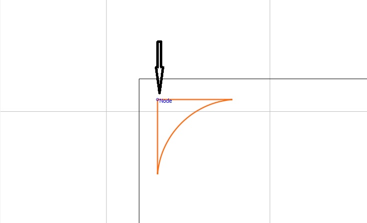
Make sure Snap to grid is on and left click and hold where it says Node and drag it to the corner. It will snap in place
1 Like
I zoomed way in to attempt to align them, so I am doing something wrong. Is there a simple explanation? I couldn’t get it to snap together for some reason. Remember,I am new at this and fumbling through.
I just figured out what I was doing. I was using the move command to place the corner instead of grabbing the node on the corner. Thanks for the help.
Here is your file fixed…but keep trying with your original so you can get the hang of it…
loom_Fixed.c2d (424.4 KB)
1 Like
 Good deal! Glad you figured it out!
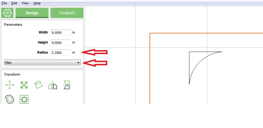
Now the easiest way would be to select the rectangle and in the Parameters box select Fillet then set your Radius required and it will do it for you. I’m using version 451.
NOTE: I did notice CC will let me do it to the outside rectangle but not to the inner ones Maybe a bug in the software???
1 Like
I was trying to get all corners the same. Correct, you can use it on the outer box, but then if you make the inner box with the offset tool, the tool won’t reach all the way into the corner because the box is smaller. usint this method all the corners are equal.
Just the way I understand it.
No, a limitation — Carbide Create can only control corners for rectangles created as rectangles in the program — imported rectangles, rectangles drawn using the curve or polyline tool, or created via Boolean operations aren’t eligible.