Matt what are you going to use for the BT30 spindle body and how do you intend to release the BT30 - looks like servo is where the pneumatics would normally be ?
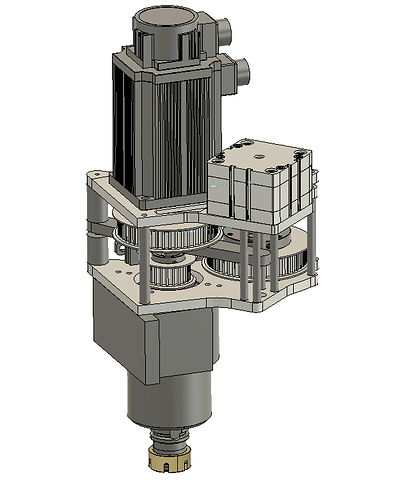
the white box is the pneumatic cylinder and theres a bar that spans across above the spindle drive cog and then pushes down on the center of the spindle releasing the tool holder.
The spindle body is already made and pictured above. Ill show more soon
4 Likes
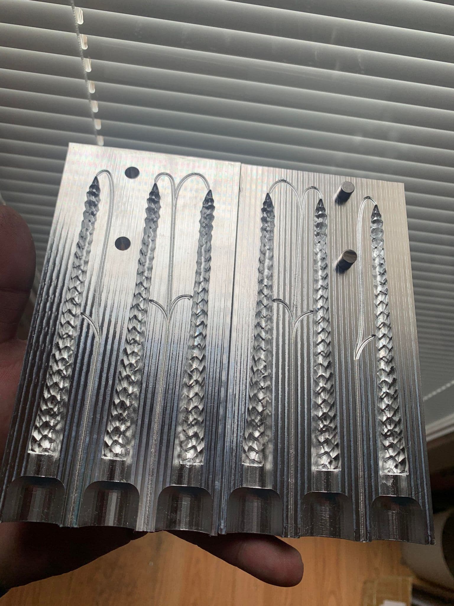
Looks almost like a fishing lure injection mold for soft rubber bait.
How much do you think your ATC setup is going to weigh and what do you think the max weight a Z carriage can be on a HDM before it starts to impact performance?
I’m still leaning towards the FM30c but it’s a heavy passive cooled spindle that’s like 26 lbs. I can add 1 or 2 gas lifting struts to avoid spindle drop when powered off but accelerating and decelerating an extra 15-17lbs makes me wonder if I will have to slow the machine down and if so how much?
Any how I like the progress you are making and can’t wait to see it in action.
Almost forgot to ask how that 3f corner radius Helical mill is holding up?
its for a tail but same exact as what a soft rubber bait would be.
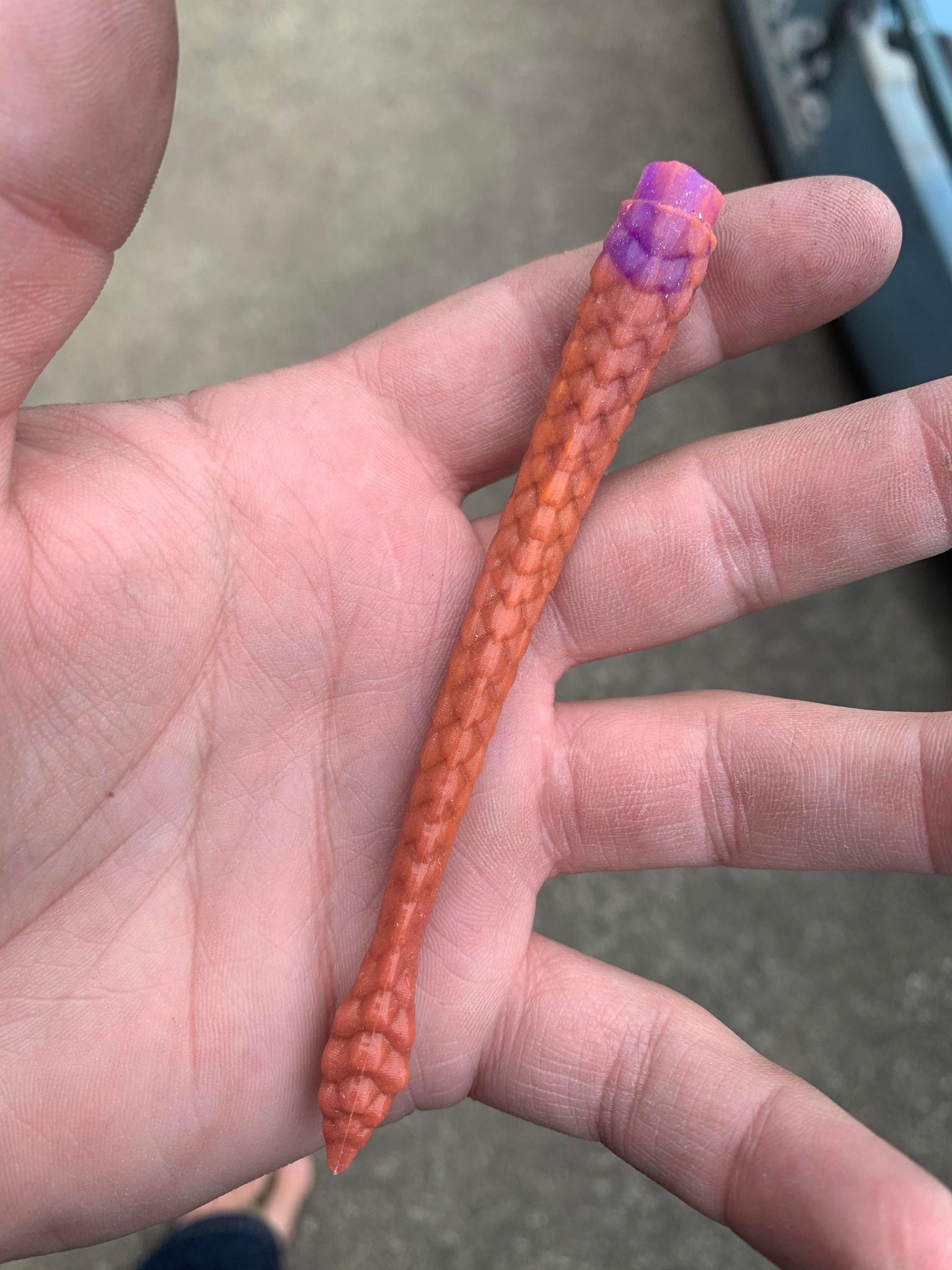
goes into a lizard i make RiverKingCustoms on Instagram - YouTube
my Z assembly weighs around 55lbs probably 60 with everything and i did some unscientific testing.
i put 45lbs on with original z axis and did some deflection testing to see what the x gantry and what the z axis would do.
pics below are from the z axis without 45lbs on the stepper and with. its pretty much on the money.
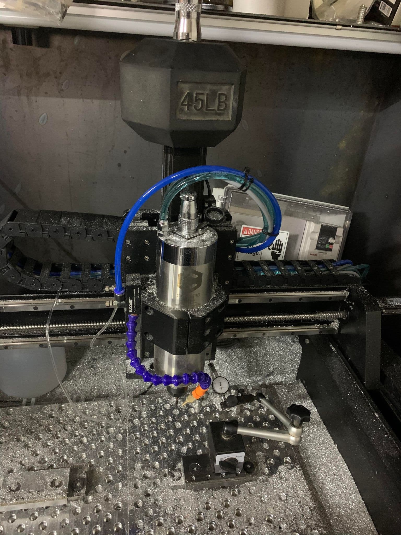
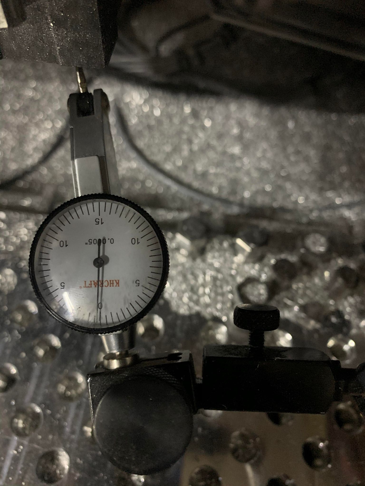
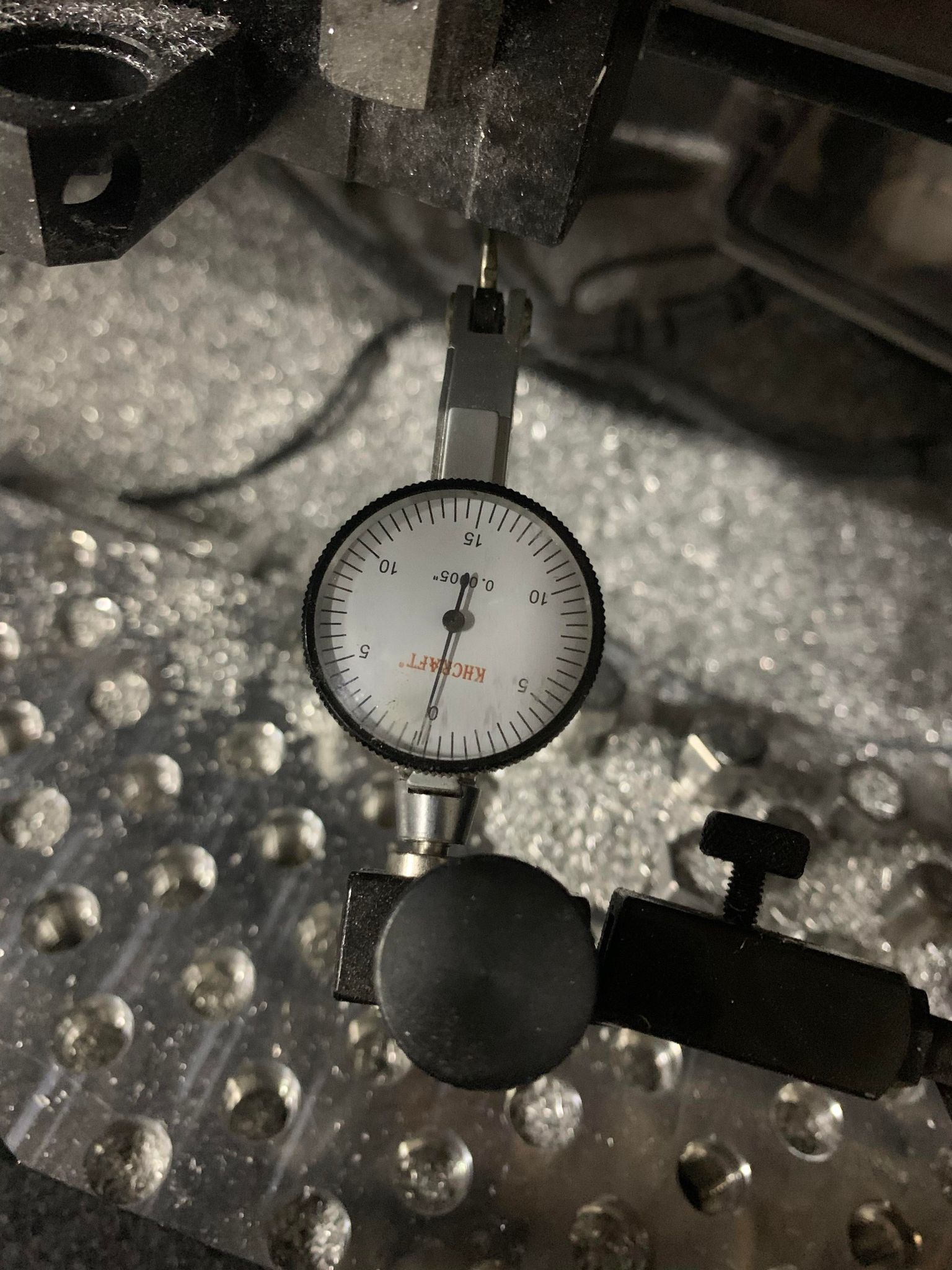
im sure with high accelerations it will have some bounce stoppping that amount. i did a bunch of measurements on the z and i can get .0015 to show up in some spots further out toward the end of the spindle mount. that said my z plate is much more rigid and wont flex like the thinner one does. .375-.5" vs 1" and it wont be moving up and down. so thats 8lbs there, plus the z rail and all that jazz.
long story short, i usually dont plunge over 20ipm on final depth unless unless im doing a 3d parallel path work in which case my machine will be slower for the trade off of my rigidity and power.
i would doubt at 26lbs you have to slow the machine at all… and if you do its only on final paths which i do anyway. (my larger concern would be the stepper handling that amount, ive had it miss steps on even 150ipm with 3d surfacing tool paths and i dont run my machine above 150 because of the acceleration causing missed steps).
3f corner radius helical tool still doing well. i ran one through my steel jaws on my smw vice and still cracking away.
1 Like
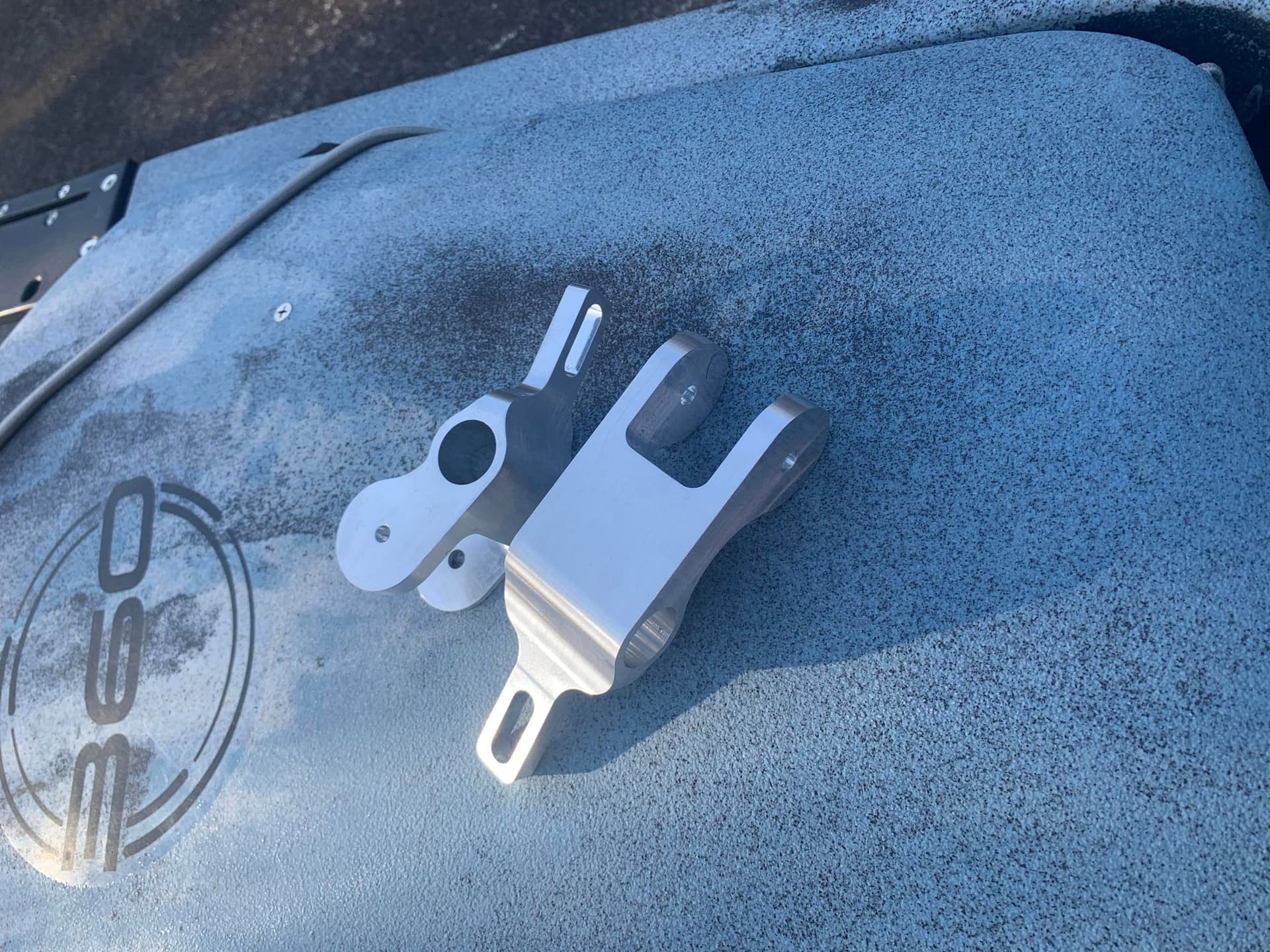
once again using tumbling to cover my mistakes and “hobby grade” appearance of some otherwise cool parts
9 Likes
These are really nice looking parts. Would love to see your setups.
This one was just a contour and bore with tabs from the top and then a plate clamped 90 degrees with a hole for a mite bite expansion clamp and two pins in it. Used the middle hole of the part for expansion clamp and then pins that held the pieces at one angle or another to allow either side to be perpendicular to the endmill.
Pretty basic though and unremarkable chattery machining otherwise there might be cool machining videos.
1 Like
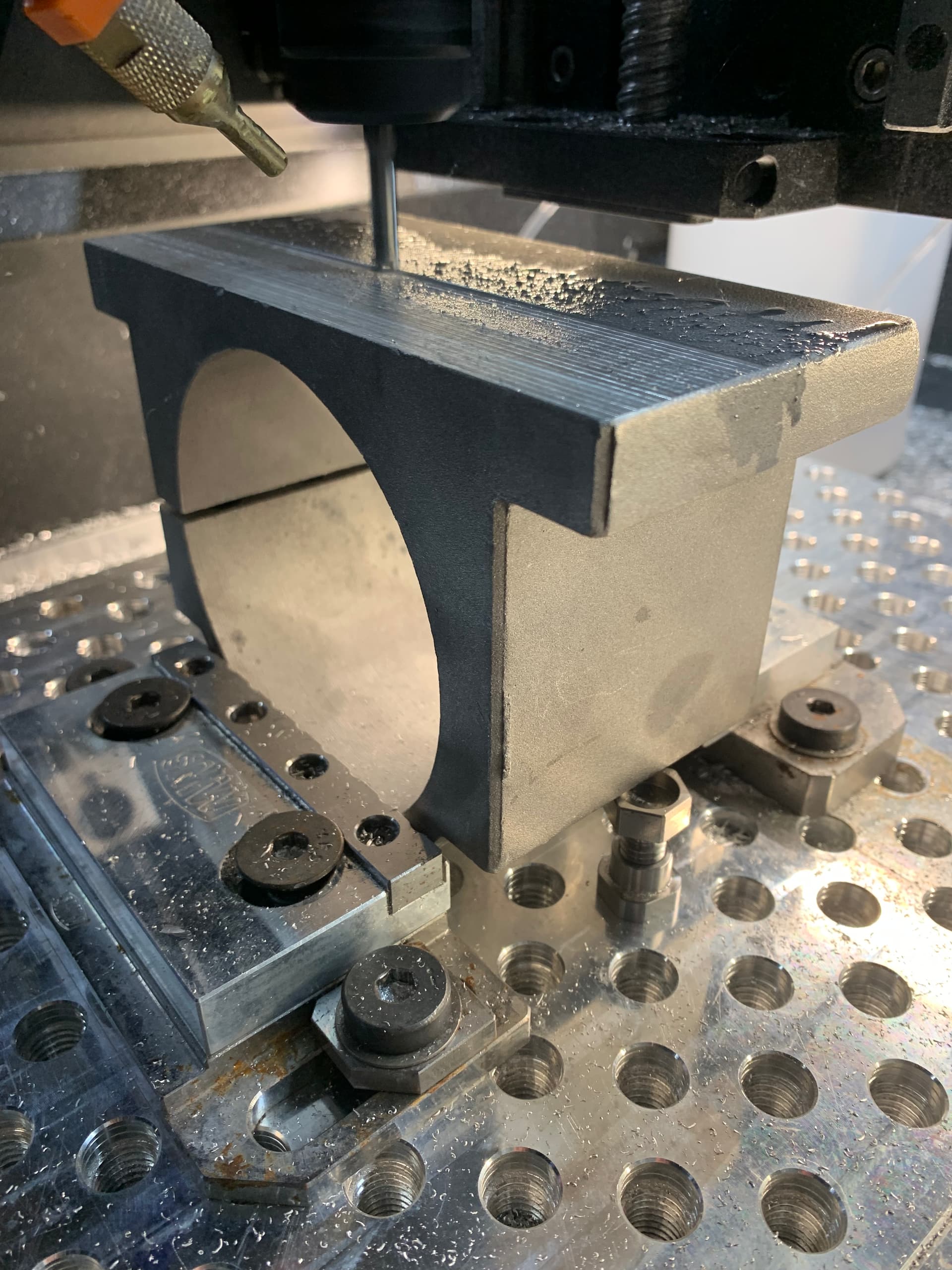
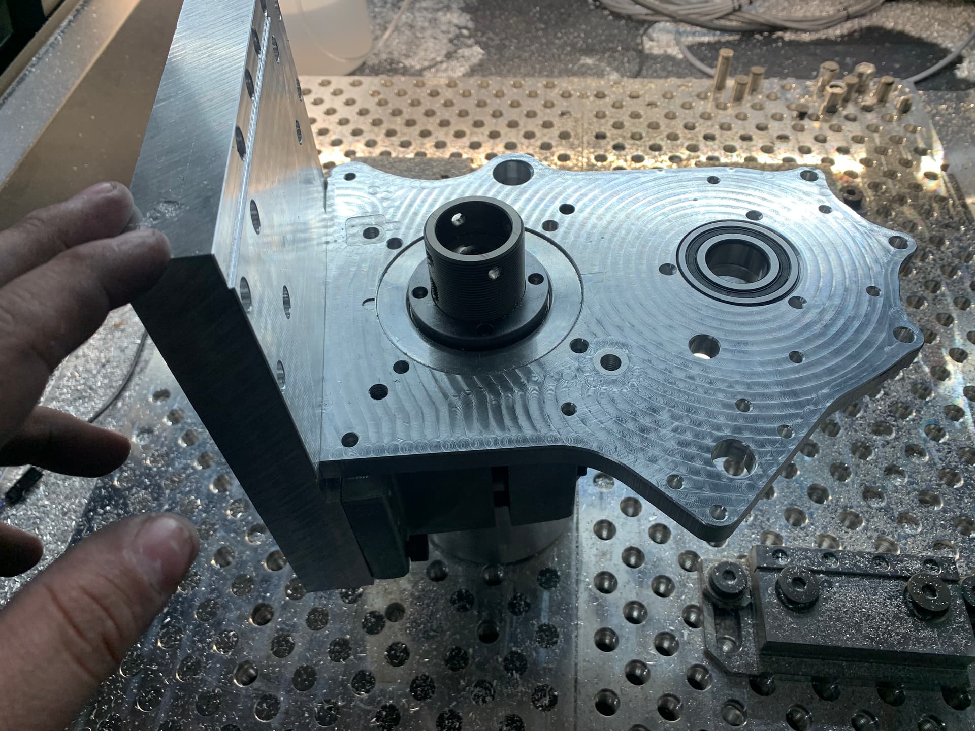
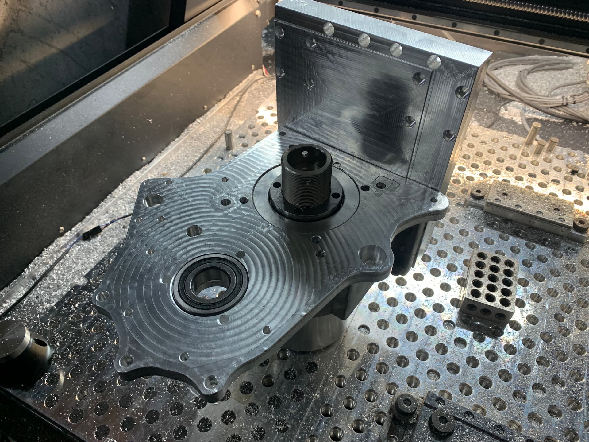
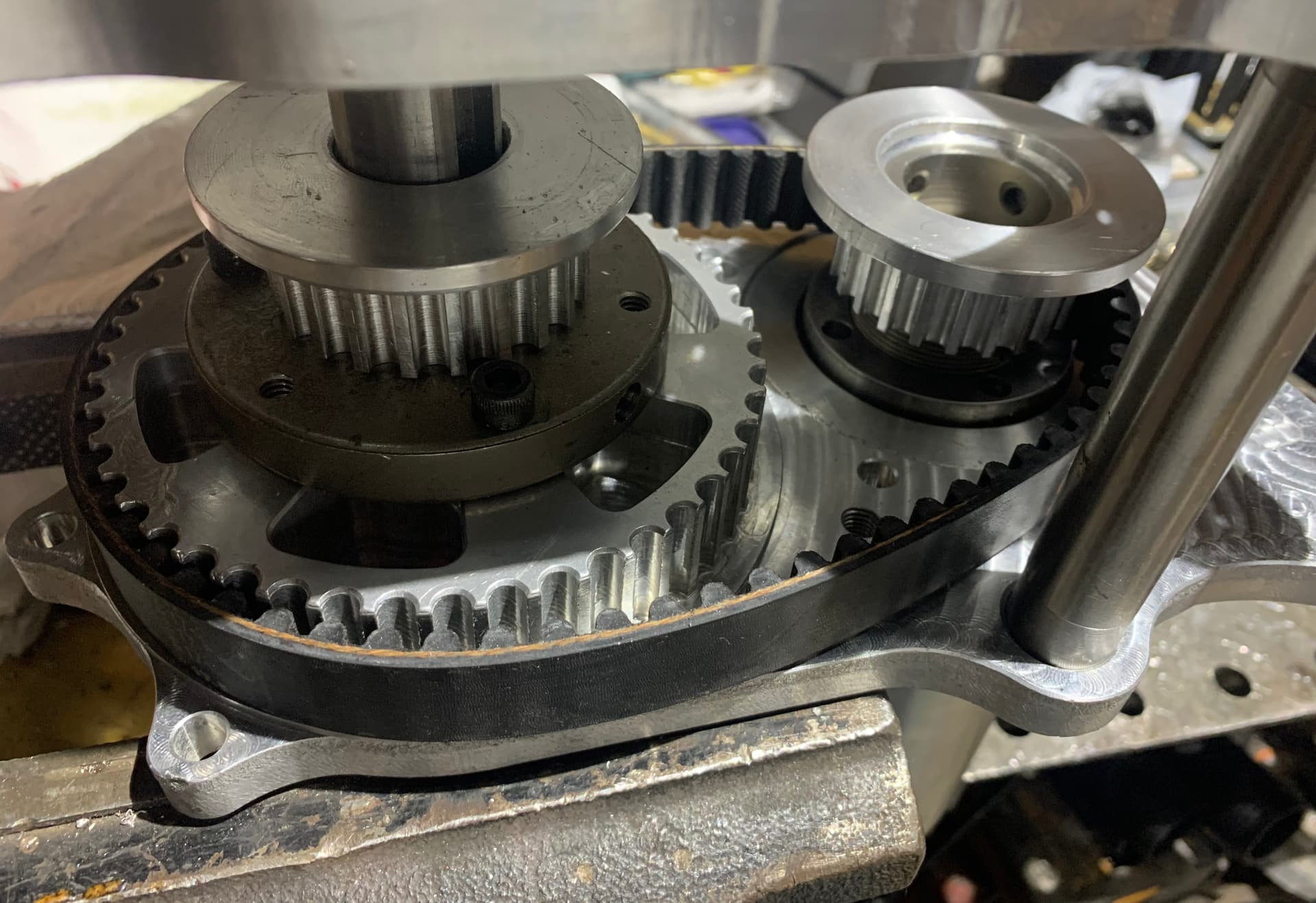
Some more progress pics.
Milling holes on the 100mm clamp.
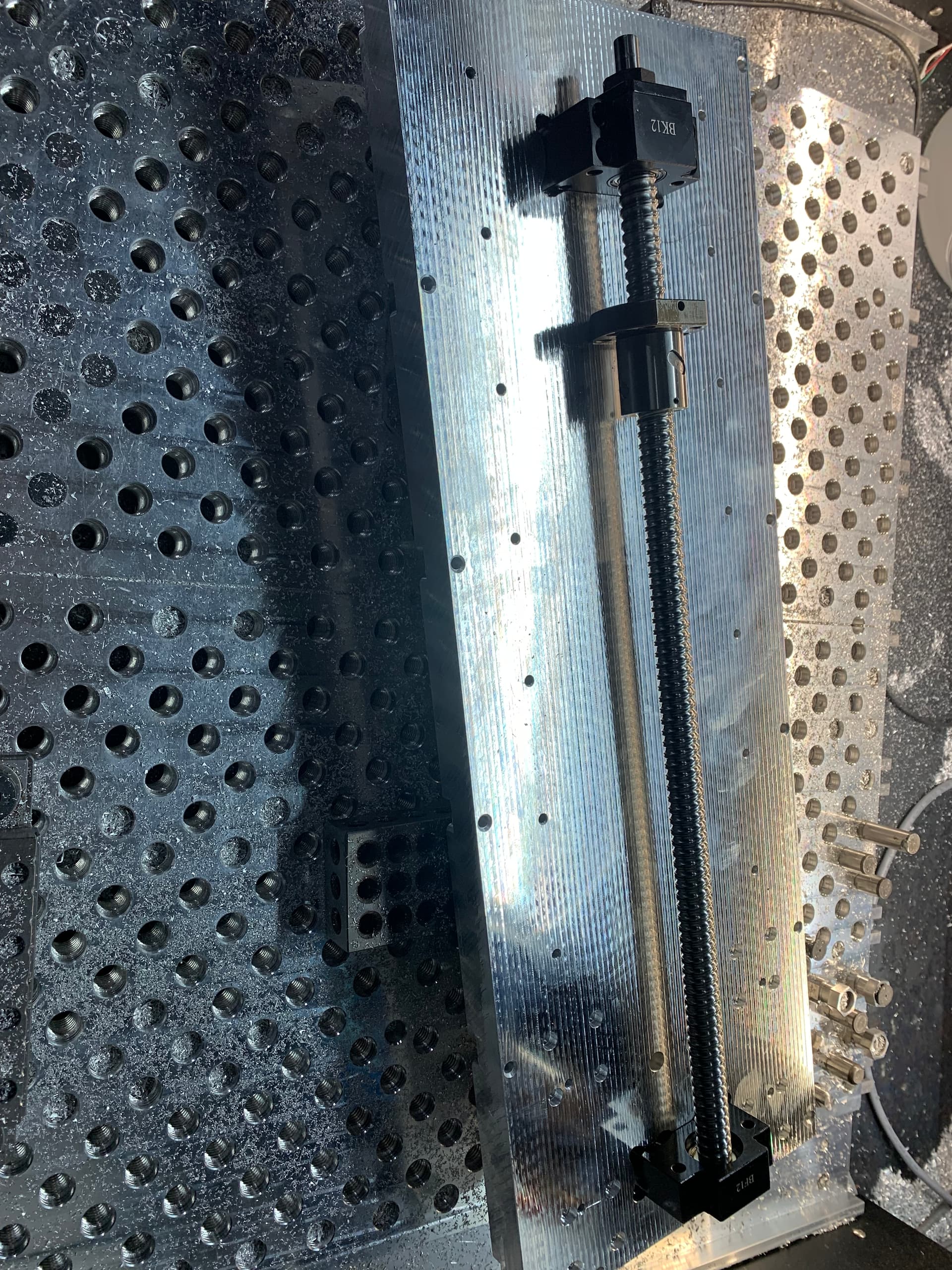
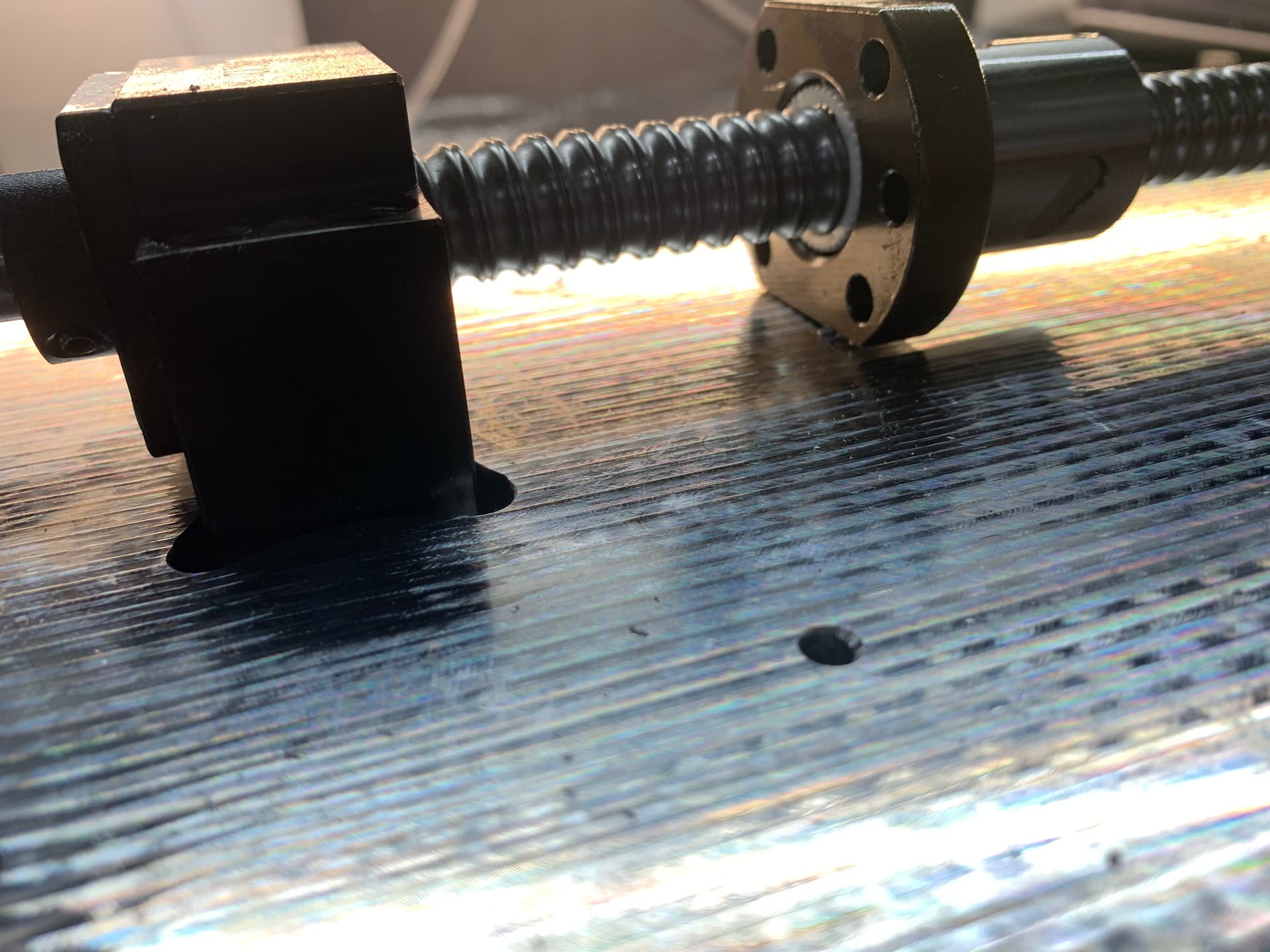
Mounting the ball screw to test my clearance. Which pretty spot on
I’ll be machining all the little stand offs and wheels for the tensioners tomorrow. So should be a couple more days and it will be all together.
8 Likes
3rd set of belts from Jeggs after the first two sets were wrong tooth size and finally got the right size…… turned out I measured wrong.
Hurrying up and waiting for a new belt to come.
7 Likes
Hah,
Been there a few times with my “accurate from the CAD” belts a few times, now I order the size below and above (approx one tensioner adjustment limit).
It’s frustrating sitting looking at a nearly working drive part…
2 Likes
looks great. love seeing the progress. are you going to post build details regarding the 4th axis as well?
Definitely will be, once this spindle is running then I’ll begin that and the tool changer.
1 Like
Really drives me nuts but definitely seems a good call to me.
1 Like
I think my mistakes so far have been due to not understanding where in the belt the ‘pitch diameter’ should be calculated from which means I get the wrong fractional diameters on the pulleys when I set it all up in CAD.
I measured from center line of the belt on this one thinking that would be the correct method but it’s definitely not. Also can’t get exact sizes but in increments of 5 and 10mm.
Just another learning experience, which have been plentiful on this build and I’m happy for them.
2 Likes
Can’t wait to see it finished. The new spindle setup will look mental, but have hard time imagining where are you going to fit the tool changer, and why the carousel style instead of a simple rack.
Do you already have a plan for the 4th axis, or will you get to it once you’re done with the spindle? I’m particularly interested in what harmonic drive are you planning on using (what gear reduction) and whether drive it with a stepper or a servo?
I’m excited to see it finished too, will mean all the works done and it’s time for machining.
Rack takes up space on the table and limits tool size(the distance between the table and the spindle) is the max. I did a rack on my other table with iso20 and wished I had a carousel. It will be much larger too going to bt30
The carousel I can have come in from the side, no tool height restriction(or significantly more space) and double the tools. Plus it doesn’t consume any table space.
The harmonic drive I have and it will be servo driven.
I show the harmonic drive further up the thread, it’s pretty overkill but that’s who I am.
I believe it’s a 20:1 off the top of my head. I’ll link the part number down below.
Also I have a rough idea on how the 4th axis will be set up but it’s not completely modeled up yet.
1 Like
https://www.harmonicdrive.net/products/gear-units/hollow-shaft-gear-units/shg-2uh/shg-40-80-2uh
this is the 4th axis im using
for all axis including the 4th axis.
ill probably do at least a 3 to 1 into the 4th
alot of this i got second hand(except the 1.25" material, belts and centroid stuff) to include the harmonic drive(it was still new in the box but its an older model).
I didn’t take into account how massive bt30 tool holders are by the desktop-cnc standards.
I see now that you attached a picture of the harmonic drive in the first post. Didn’t realize that’s what I was looking at.
Very fun build, any progress? ![]()