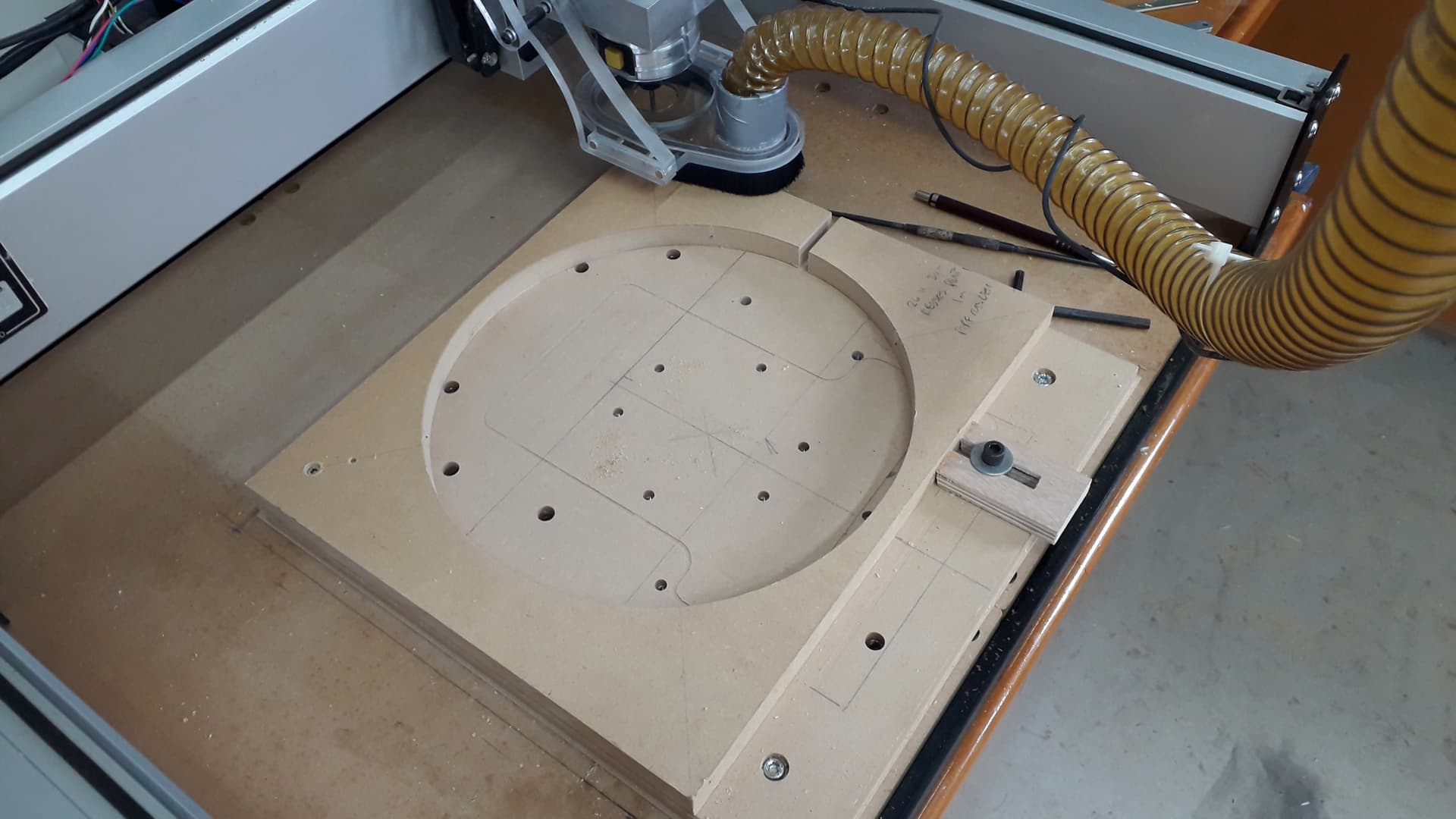
A friend of mine asked me to make him a paint carousel for his hobby desk, I am new to all this and my machine is fairly old so am using it to learn on at this stage. I am happy with the discs which I cut on my spindle molder then transfer to the Shapeoko to pocket and cut in a pipe groove etc. I cut a circle with the Shapeoko to hold the pieces and then fixed it to the bed and clamp the circular ply pieces in to do the cutting. My center alignment must be out as when I put the pieces together it looks a little like a crankshaft! I am setting my start point by eye and used a 6mm straight cutter so no surprise I was out, each time I change a cutter I then rezero z and use the x,y the machine remembers. Would I be any better using a top left start point, rather than the center? Is there a way I can improve the accuracy with what I have at this stage.
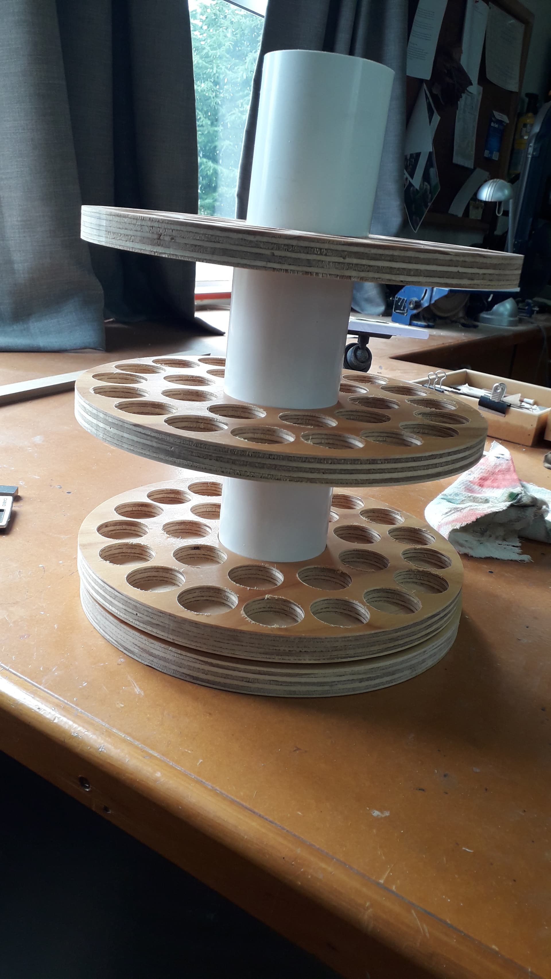
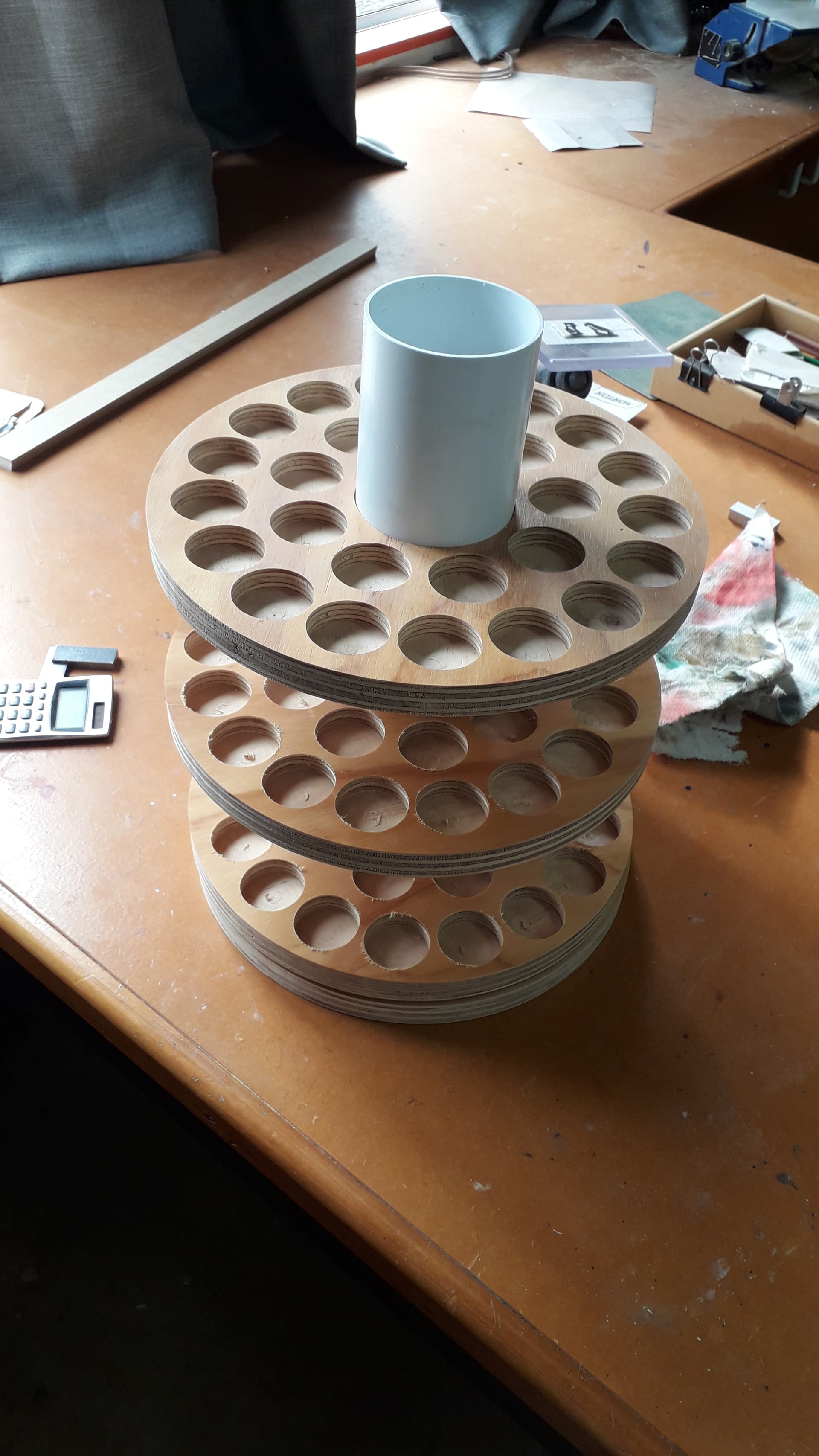
One of the photos of the tower is exaggerated as I didn’t put it together properly but you will see what I mean.
The way I do this sort of thing is set up a fixture so that it can be reliably positioned on the machine and secured, then I machine it using one of the Rapid Position points as an origin.
Thanks Will I will give that a try, am I correct in thinking the rapid positions are a constant?
The Rapid Positions are consistent w/in the limits of machine steps and homing switch sensing.
They will only shift beyond that if:
- homing switch position is changed (they’re slightly adjustable)
- XY Travel dimensions are changed (the Rapid Positions are calculated using the overall Travel Dimensions)
Thanks Will thats really helpful, I learn new things each time I do something.
As @WillAdams suggested use a rapid position. However if you have a round piece that you need to find a center you can make yourself a centering tool.
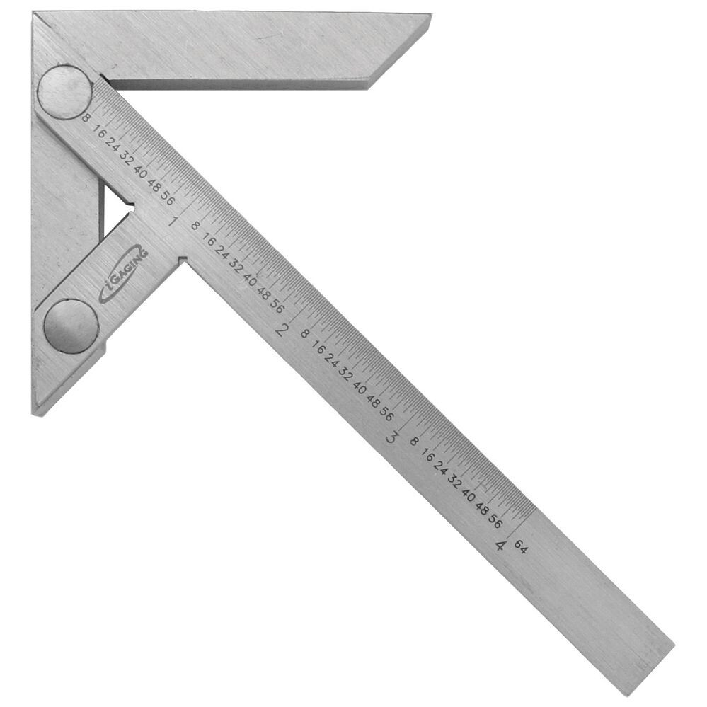
This picture is used in wood turning but is only 4" long. You can likely find a longer one but if you look it is simply some 45 degree angles. You put the two short legs on the edge of a perfect circle and mark a line approximately in the center. Then move the gauge 90 degrees and mark an intersecting line. If the circle is perfectly round this will work. If the piece is not perfectly round keep moving the gauge 90 degrees until you get 4 marks. From the marks you can estimate the approximate center. Simply use some plywood to make yourself a marking gauge. You can make the tail as long as you want. The two short legs only need to be a couple of inches long. You must assemble the gauge very precisely to get good results. You should conunterbore the connecting bolts/pins so they do not interfere with the gauge laying flat on the project.
You could cut the short legs as one piece and the long leg a single piece as long as you want with the 45 degree angles. Since they are outside cuts you should get sharp corners. Inside corners will be half the diameter of the bit. Both pieces form an equilateral triangle.
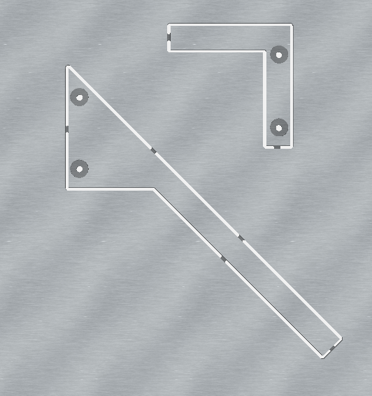
I drew this up quickly. You can change it anyway you like. The material is .5" thick with .75" counterbores .25’ deep and a .25" through hole for bolts. I made the tail 16" long.
Basically I drew a 1" x 16" rectangle and angled it 45 degrees. I then edited the nodes to make the 45 degree at the top left side. Then I drew a 5" equilateral triangle and did a boolean for the two objects.
I then created two 1" X 5" rectangles and turned one 90 degrees and then did a boolean to merge the two into the L shape.
I created the large circle and small circle and copied and pasted so I had 4 sets. Then put them in place and grouped 2 sets of the circle with each of the L bracket and the long arm so they would line up.
I used a #102 1/8" bit to cut everything out. In the simulation the L bracket is mirrored because when it is cutout you would flip it over so the recesses would be on each side with a bolt and nut holding them together. In the actual c2d file I have the two pieces merged together to show them and there are no tool paths for that only the two individual parts.
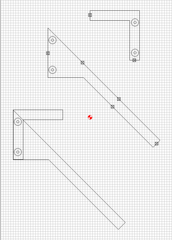
centering_gauge.c2d (72 KB)
If you use the file be sure to modify the job setup. I use bottom of material and center as origin.
Thanks Guy that is a great gadget. I would like to make one for my use. The circle is fairly good as I set up a movable base board on my spindle molder table, then screwed a piece of mdf laminated on both sides with Formica, this gives the pattern more strength when running on the bearing above the cutter block on the molder. I then just cut the circle on the molder while it turned around the screw in the middle, simple but it worked well. I made this to make round bread boards many years ago, so decided the radius was ok for this project too. You probably have similar patterns being a wood worker who will be used to making patterns and jigs to hold work pieces, as you machine them. Thanks Joel
Has anyone ever asked for a feature in CC to name a physical location (like a Rapid Position?). I think that would be very useful for those who have “permanent” fixtures on their beds that help position the origin.
I could see the “named” position(s) available on the Rapid panel (and also on the quick menu).
You could make a Quick Action (that you name whatever you like) to move to any particular location.
Hi there I tightened everything up and added a little more tension to the left hand belt, as it was a bit looser the righthand one as Guy suggested . I recut the circle and the error of offset seemed to travel through 90deg but was still there.
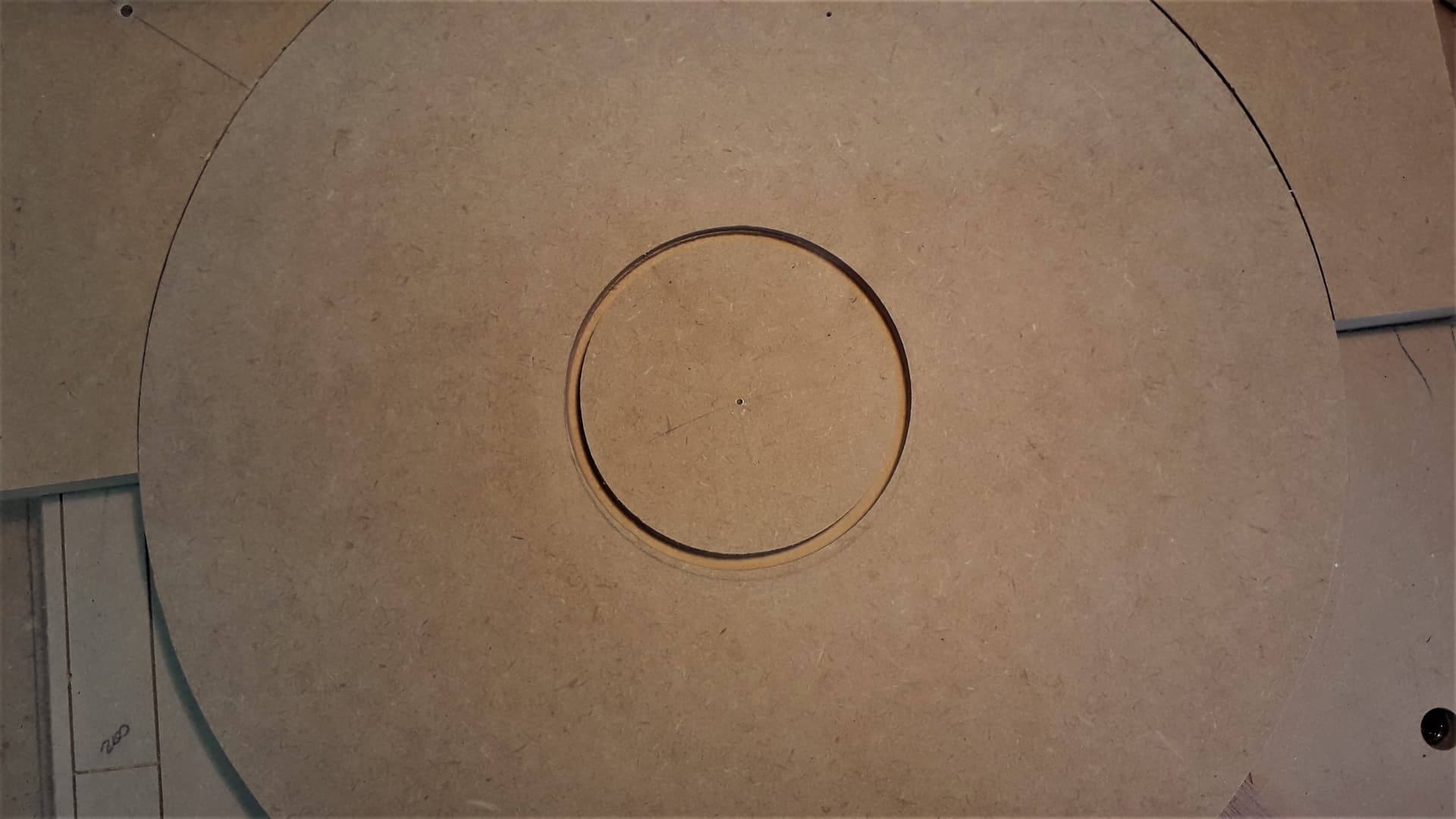
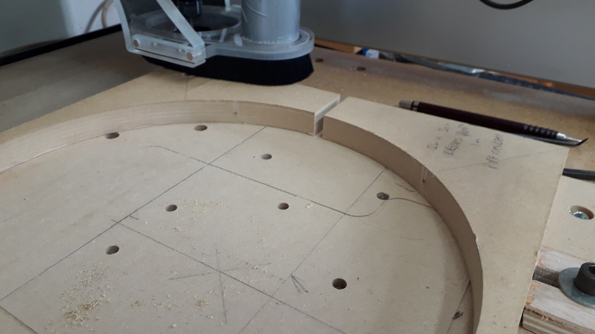
The image I sent shows the circle drawn with a compass using the centre point I set on the machine with the V cutter so it was as good as I could get it, but it still isn’t round.
I then cut 2 rectangles into the base board with a pointed V cutter as per the belt tensioning checker that Will sent through and made them 20mm by 340mm.
I measured by putting a scalpel blade in the bottom of the V and pushed a Toledo steel rule up to it then, measured the same way at the extent of the cut.
X came out at 340mm
Y came out at 339.5mm approx. 20 thou under is that an issue?
This topic was automatically closed 30 days after the last reply. New replies are no longer allowed.