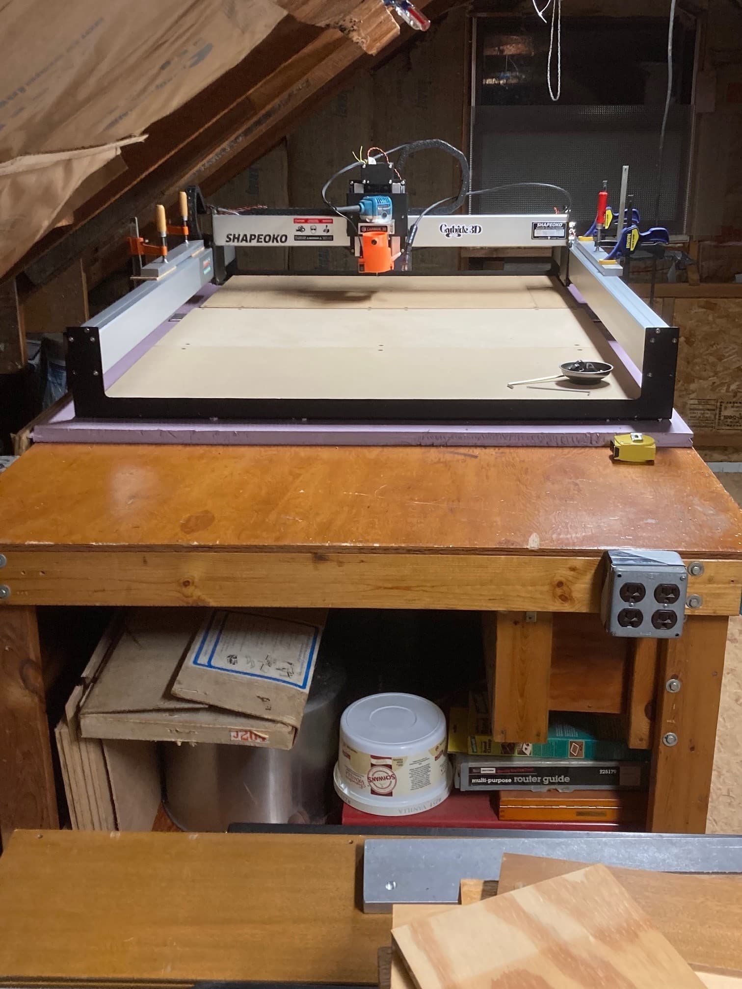
Combining the XL with the expansion kit is slowly happening. Here the rails are temporarily aligned with bars and clamps while the bases are squared. (78 inch diagonals, 64 inches long). The two bases will be attached with a 47 inch x 3 inch x 3/16 inch aluminum strip, drilled and tapped in alignment with the bases’ MDF holes. When that is done I will decide how to attach the rails. I am leaning towards two 1/4 inch x 1 inch strips of aluminum or steel maybe 20 inches long 'for each side. One on top and one on the bottom of the rails, screwed to the rails which will be drilled and tapped. Similar to the temporary 3/4 inch aluminum bars in the picture. Slow process, learning as I go.
When you fire this up remember that CM remembers your last machine (XL). So connect and go to settings and send a config before you try to initialize. I had an XL and an XXL and you could use the xxl on a job and if you used the xxl again all was good. But if you used the xxl and then attached to the xl you had to send the config. CM remembers the last time you sent a config and assumes you are only running one machine with CM.
Since you are making a custom Shapeoko you will need to figure out your Y length during the configuration process. If you have a BitSetter then disable it during the initial setup because as I said above CM remembers the position of your BitSetter from the previous config and will try to go there to set bit height. Because the BitSetter is no longer where it was it will cause a headache.
Just letting you know that there are blocks available to join the extrusions.
https://www.3dtec.us/product-page-1/carbide-3d-shapeoko-3-extrusion-splice-block-2-pack
If you haven’t already seen this video on YouTube;
1 Like
Thanks gdon. I will post a reminder above the machine. Completion may be a few weeks/months away. Ample time for me to forget.
Hi Andreas. Thank you for the reference for the blocks. I have seen them and have also watched Chris Powell’s video multiple times. Without his video I probably would not be doing this. The blocks are a bit pricey for me. Other than the expansion kit and new longer belts I am trying to use materials already on hand.
I know @krtwood had a video on YouTube extending his SO3, but I can’t find it anymore.
If I remember correctly he used blocks of MDF to join the extrusions.
Okay. Changing as I go. First I got rid of the three pieces of MDF and replaced with one single piece 63x 45 inch. This is mounted direct on the metal straps that were original to the X and XXL. No feet, laying the metal straps direct on the foam. On top is one single piece wasteboard 33x55 inch. This is much better in terms of leveling and squaring. Metal straps from the XL were shimmed up 1/16 inch at the end to bring the MDF to the same level as the XXL strap end. To join the extrusions I have 1 inch aluminum angle on the top outside edge and 1.5 inch aluminum angle on the bottom outside edge. I drilled and tapped 10x32 threads in the extrusions to mount the aluminum angle. ( Angle was predrilled with #21, clamped to the extrusions, and used as a drill guide to drill the extrusion.)
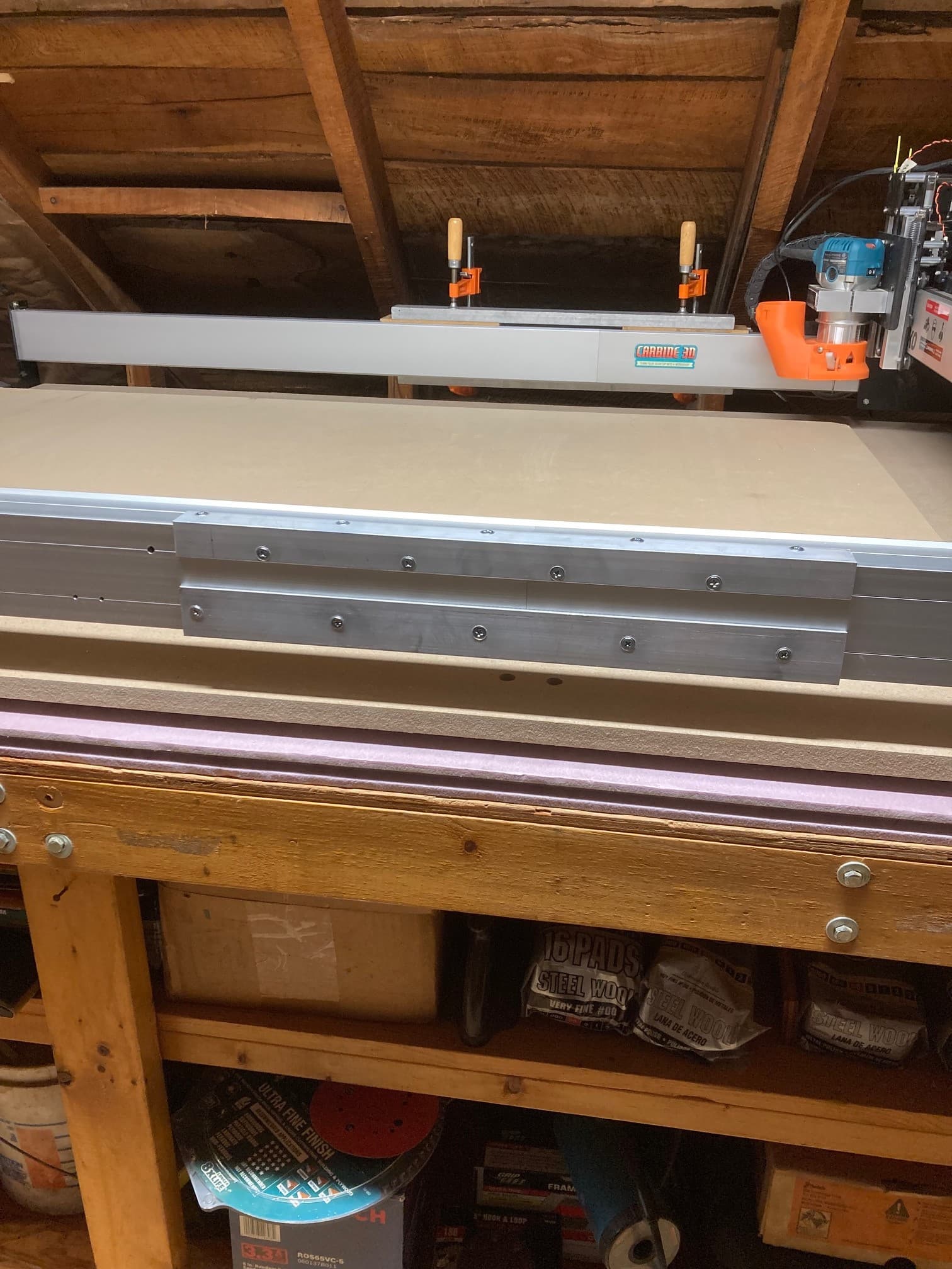
This was very convenient. Extrusions essentially self aligned when the angle was clamped (clamped top to bottom and inside to outside) and drilled. One inch aluminum angle on the top to avoid the belt and pulleys. Holes were drilled 3/4 inch from the edge on the extrusion to avoid the corner channels on the inside of the extrusion. There are no splines inside the extrusion. These are entirely joined by the aluminum angle. Alignment is excellent and very rigid. Seems like a good option so far.
1 Like
Did you join the straps underneath to connect the front and rear steel endplates?
Hi Liam, I did originally but have removed the connecting piece (it may go back in). Two holes can be seen in the MDF, just under the rail in the first new picture. The connecting piece is threaded and will slide under the MDF at these holes allowing me to fasten the straps together through these and other holes (12 total across the MDF). The single piece MDF is also drilled to match the threaded holes in the original straps tying the ends, all straps, and MDF together with about twenty screws, maybe making the connection of the straps less necessary. When I had three pieces of MDF, I tried to use the connection of the straps to square the base but now squareness is dictated by how true the new one piece MDF is cut and drilled. With the current setup, corner-to-corner measurements are within 1/16 in.
1 Like
Sounds like they’ll be joined pretty well by the MDF sheet.
Have you considered putting a couple of vertical supports in between the baseboard and the Y axes along their length to reduce their horizontal and vertical deflection over the long span? (That’s what the SO Pro does)
1 Like
I have not considered that. With the space open I can in theory put a 63 inch round on this machine and by spinning it on an indexing pin, cut the entire thing. Like a giant Pennsylvania Dutch Barn “Hex” Symbol. That is cool. I know there is deflection there and maybe more on the router mount itself but I am mainly after size at this point. Accuracy will probably be next. It is genuine fun to play with this machine.
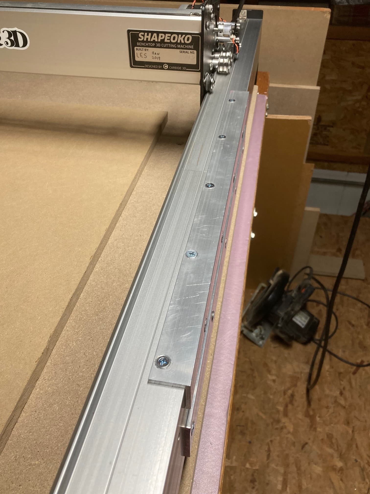
Another update. Both rails are now joined with aluminum angle and the machine rewired with the new drag chain/wire harness that Carbide 3D sent as part of the XXL upgrade kit. Like Chris Powell said in his video, there is enough wire to do this expansion without making wire extensions.That part is all good but I am now not so sure how the aluminum angle is going to work out. What seemed like really good alignment at the junction of the two rail lengths, is far from perfect. When pushing the gantry back and forth over the seam, I could hear and feel the v wheels make the transition. I know I spent at least two hours, loosening screws and bolts, tapping with a rubber mallet, re tightening etc, etc. They are now “pretty good” but still the transition is noticeable. If anyone else tries this, the key seems to be clamping the rails and angle together in alignment and then drilling holes through the angle and extrusion at the same time. If your holes are perfect, countersinking is good. If your holes are like mine (not so perfect) skip the countersunk holes, they may work against you. Rigidity is great and should not be an issue with the joined rails as long as the screws do not come loose. I will be able to power this thing up tomorrow but I still have surfacing to do to the MDF / spoilboard and I want to wire kill switches on two sides of the table. Surfacing may tell me how bad things really are.
1 Like
You could add a machinist jack style support under the joint to support the weight and assist you with dialing in the alignment.
1 Like
A jack would not hurt but I am not seeing so much sag as the aluminum angle does a good job of preventing it. I am seeing more like a slight radial misalignment. I think I may need to machine a pair of alignment parallels out of 1 inch thick acrylic, each maybe 5 inches long with a v groove cut that will fit the extrusion. First loosen up the aluminum angle, clamp the alignment pieces on the opposing top and bottom V ridges of the extrusion and then tighten up the aluminum angle pieces.
Alignment seems fine when jogging around the bed, v carving will be the real test (I have not turned on the router yet). I only had to change two settings in Carbide Motion to account for the expansion. Table Y is now set to 1450 mm (this allowed it to jog and rapid the entire length) and $131=1450. $131 = 1450 was necessary for proper homing from far away, otherwise I got a homing error. I do have soft limits active. I spent a lot of time cleaning and going over v wheels and belts and I recommend everyone do this periodically. Really look the machine over close. I found v wheels which did not roll smoothly but it was only noticeable when they were tightened to the gantry. Taking these apart showed small black pieces between the bearings and all it took was wiping them out to correct them. Close inspection also found one belt pulley which was making contact with the X extrusion just below where the v wheels run. It had cut a small groove in the aluminum so it has been doing it for awhile.This I corrected with a thin aluminum shim to move the pulley away from the Z plate where it is bolted. (I bought the XL used so it may or may not be assembled correctly.The nearest V wheel looked correct but the pulley was sharing its load.) I tightened X and Y belts by turning on the machine so the steppers were actively holding and then pushing/pulling the X and Y axis looking for axis movement due to belt stretch. I was able to eliminate almost all in the X axis but the belts in Y are very long now and I was not able to easily tighten them to prevent movement (maybe good enough). Jogging now is very smooth in all directions, the steppers sound very consistent. The other thing I recommend, is to become familiar with grbl settings. It seems like a significant number of problems new users could have might be remedied with minor MDI changes to dial in the machine. Next I need some threaded inserts to finish the waste board.
On those long Y runs you might want to consider either the 15mm belts (you can get the parts on AliExpress) or upgrading to the kevlar cored 9mm belts to reduce the belt deflection in Y.
I dont know much about AliExpress. Are the suppliers reputable or do you have to be careful? I am leery of some offshore quality and even question if the “Gates” belts I have now might be counterfeit. They don’t feel the same as the ones which came from Carbide 3D.
I looked the pulleys and steppers over today and I wondered if 15 mm belts might be a difficult upgrade. Have you done it? If so, what all had to be changed and about how much did it cost? It seems like there might be more to it than first meets the eye.
I did a slightly more complicated upgrade but I used belts and pulleys from Powge and the “Powge Transmission Parts Store”, which seem to be the same company on AliExpress. They ship on time, the parts are good, I always got what I ordered, no complaints at all. If you look really carefully at the pics of the SO Pro you might see their logo on the belts…
If you want to try the simple option first, I’d use the kevlar cored belts, at 9mm these will give the same tension modulus as the 15mm belts in fibreglass core. I got my set here
There are US vendors as well, not sure where you are though.
If you want to go 15mm then you need new pulleys for the motors and some 15mm belt clamps which is more work. I machined belt clamps from Aluminium but you could 3D print a wider variant of Neil Ferreri’s belt clamps too.
The 15mm belts will put more load on the stepper shafts and you’d need to be careful not to overtension them or you’ll work harden the stepper shafts and they’ll snap (more easily than with the 9mm where you can do the same thing).
I’d suggest you try the kevlar cored 9mm first and only mess about with the 15 if you have to.
Thank you for the good information. I would not have thought of work hardening occurring (unfortunately not a machinist). I may source the kevlar belts if I see problems. I dont plan on doing much metal on this (have access to an old Dynapath CNC if needed) and tend to think problems are an indicator that I am trying to do more than the machine was intended to do.
1 Like
Pretty much done and it makes the 3XL I started with look miniature. Waste board is on. Threaded inserts are on 1.5 inch centers. Hopefully I never have to remake it. After the machine drilled the holes, I countersunk them from the bottom. Then about 740 inserts. If you don’t have an air compressor / impact driver, it will take forever. Even with, it was more than I wanted to do at once.

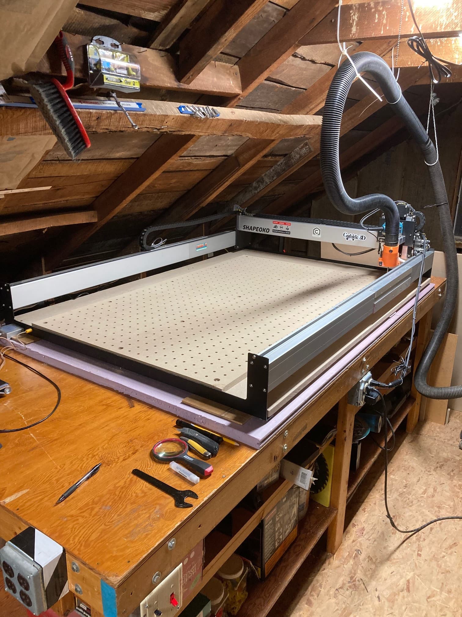
Added switched (black switch) receptacles to turn off the router and vacuum but leave the computer and Shapeoko on. Then all receptacles on the 4x8 table are switched again (red switch) to kill router, vacuum, steppers and the computer all at one time. All runs smooth, no issues. I still need to surface the wasteboard. Checked for zero and have a 0.065 inch variation in z zero across nine spots. Overall, very happy with how this turned out but one should know their own capabilities before jumping in. It took time and probably $900 (~600 for the XL to XXL upgrade kit which may not be available now from Carbide 3D, $120 for inserts from Carbide 3D, ~$40 for aluminum angle and some minor hardware from the save 11% store, ~$120 in MDF and foam from the same place). I had all the drills, taps, and electrical wire/boxes, switches and receptacles. What do I plan to make with this? Signs (maybe big signs), acrylic, some small engraving. Now if I make something that would barely fit on the 3XL, I can make two or three or more at one time. No business or product line and so far I have never sold anything, just enjoy messing around sometimes after work. Thank you Carbide 3D. Great product, great people. I stumbled onto the original 3XL used 2 years ago and it has been a source of happiness ever since. Very cool. Cheers.
8 Likes