Alright, thanks! Going to attempt this spoilboard in a few minutes, I think.
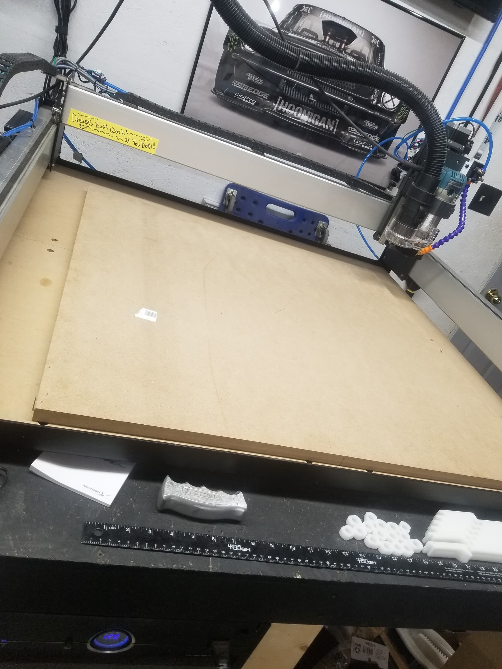
So… I had cut my supplemental wasteboard to 33x33, and postioned it forward more, and stapled it down, then realized I was too far left, for the spindle to reach the BitZero, and readjusted and secured it back down.
Here is where I finally am. ![]()
Well, I know this is about as basic as it gets but, I decided to just run it, and it’s a start, at least! I really can’t thank everyone who commented enough, cause it was a little nerve wracking! Extremely humbled for the exemplary assistance with this, I’ll hopefully have my threaded inserts in a couple days(online order) and be back with an update on my original project. Beyond stoked!
1 Like
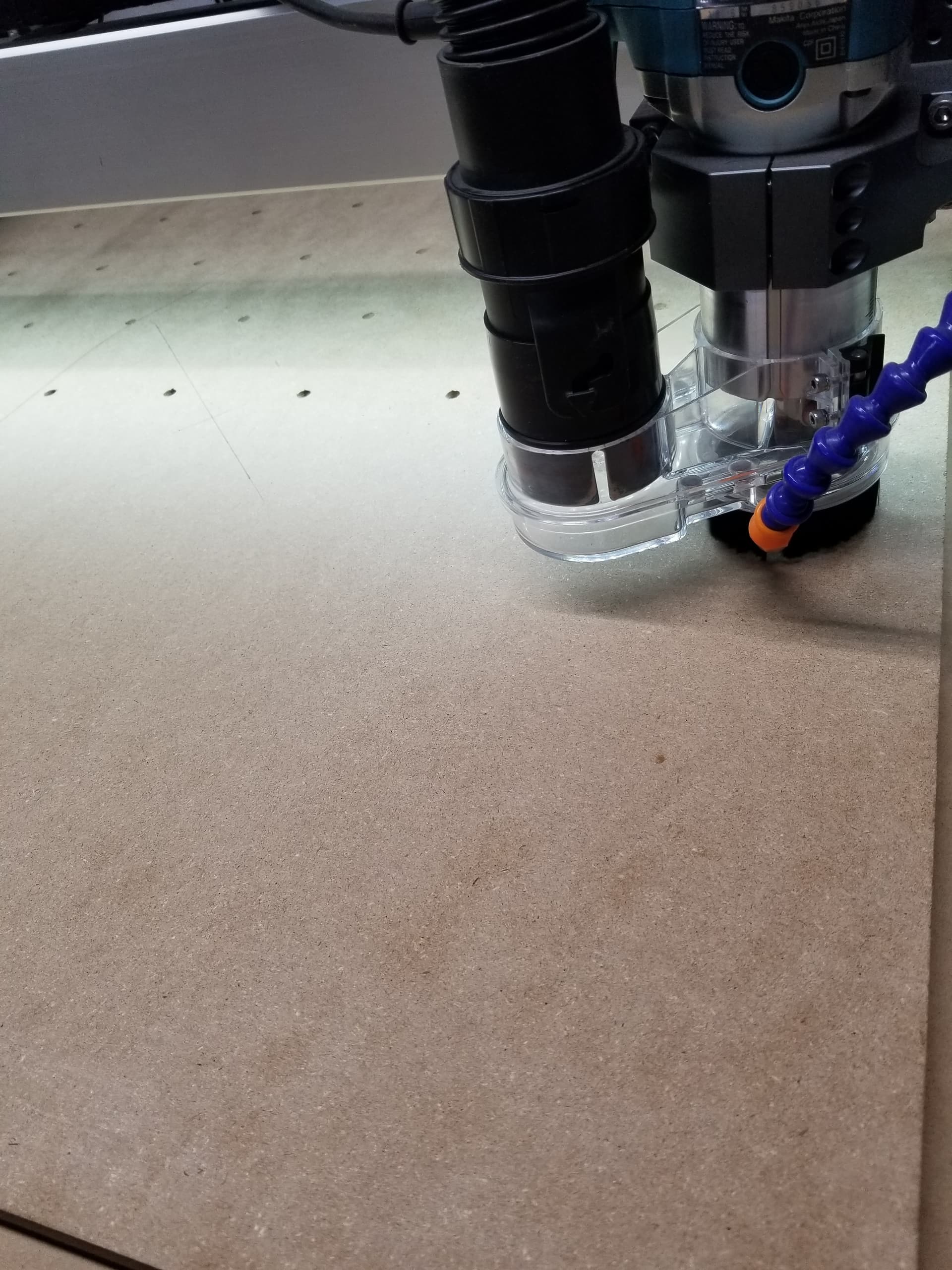
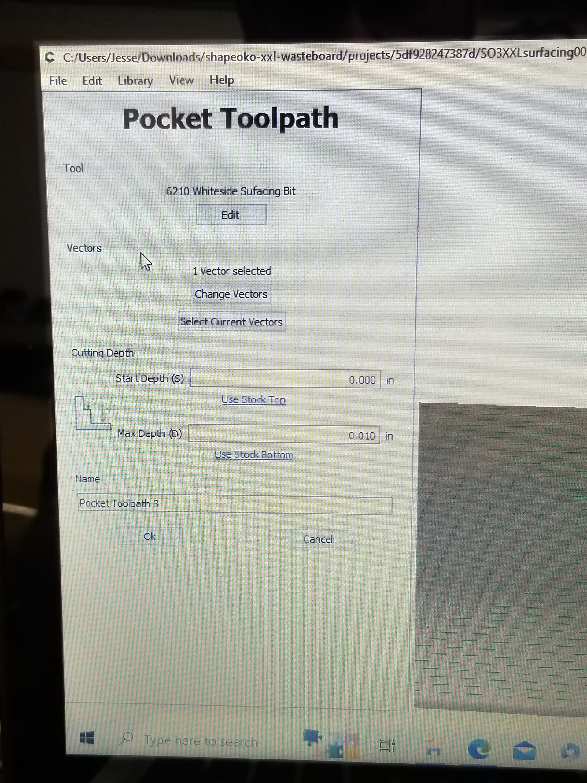
So, I setup a file to surface it, cause I remembered having the Whiteside #6212 cutter, and at 0.010, this was the cut depth, cause it didn’t sit on the BitSetter correctly. I did go through and tram it awhile back but, does this look bad?
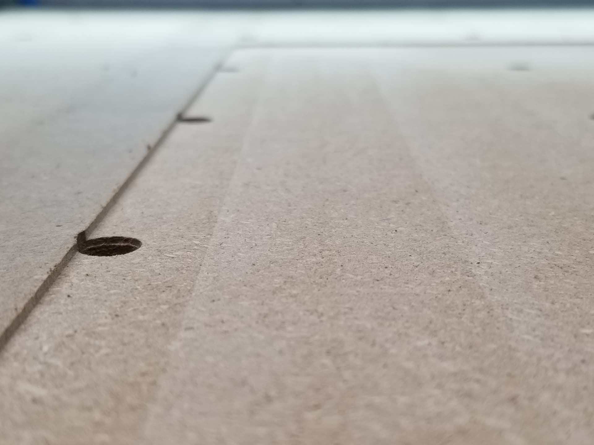
It does not look bad. If you can not feel a noticeable lip you should be good to go.
I have taken the time to use a feeler gauge, jog to various spots to see how close zero was at each spot. Zero at one spot, move, lower to the feeler gauge and see what Zero reads on CM. Rinse and repeat.
Good Luck
2 Likes
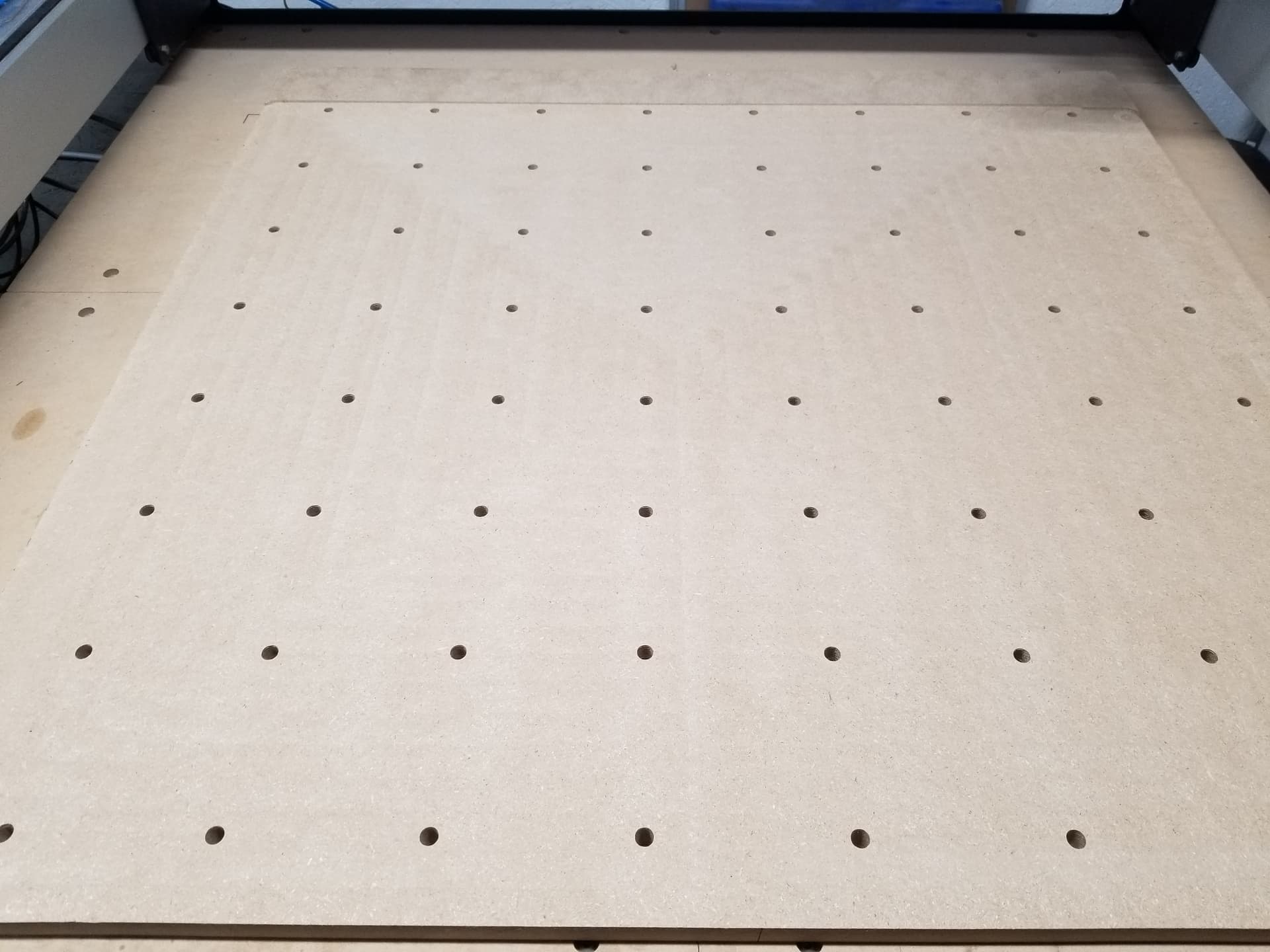
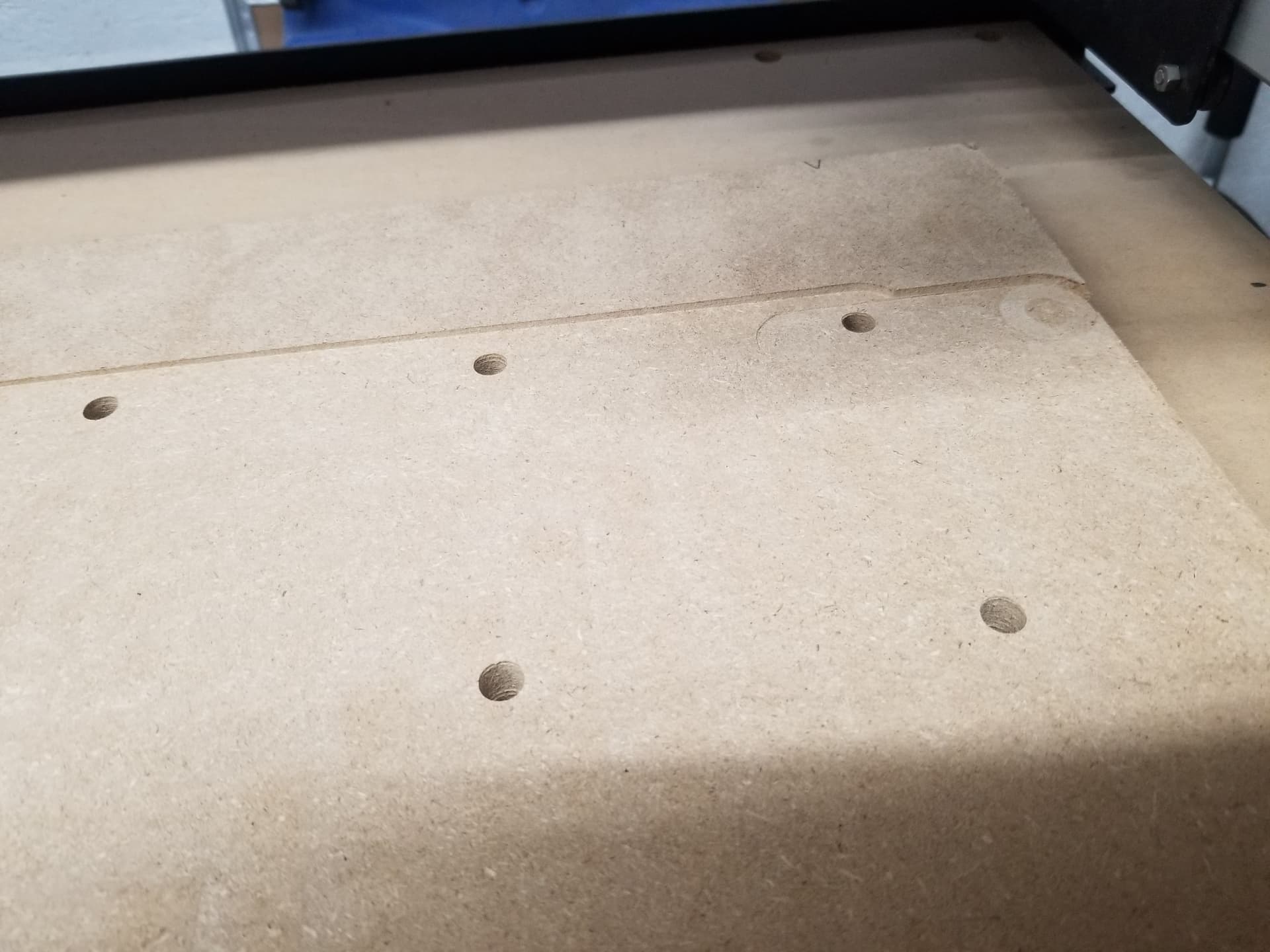
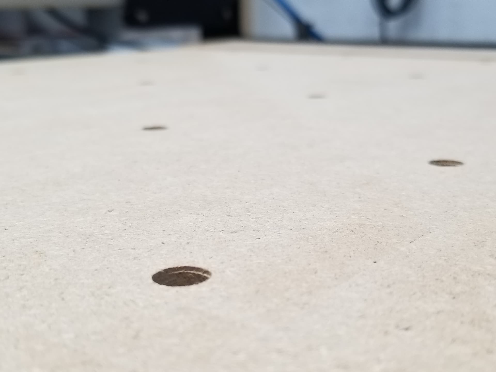
Attached are photos, that kinda show where it’s uneven. The center seems to be the worse, as I can feel it step up some there.
As it was on it’s last pass, at the rear left, it did seem make a weird sound and continued on(where the uneven spot is, at the rear right, that was me manually trying to even the back out there, as it did not do that spot).
Overall, I’m fairly happy to have even made it do something.
I wasn’t even sure what speed to set the router to, with the surfacing cutter, so I adjusted between 2 and 3, to what I thought sounded “okay”.
Mind you, I only had three staples holding it down, which idk whether that played a factor in it or? I’m not sure.
1 Like
As long as it did not move, three worked for you.
Speed… I use 10k rpm. 65-75 ipm
2 Likes
How can I know what RPM each speed is on the router?
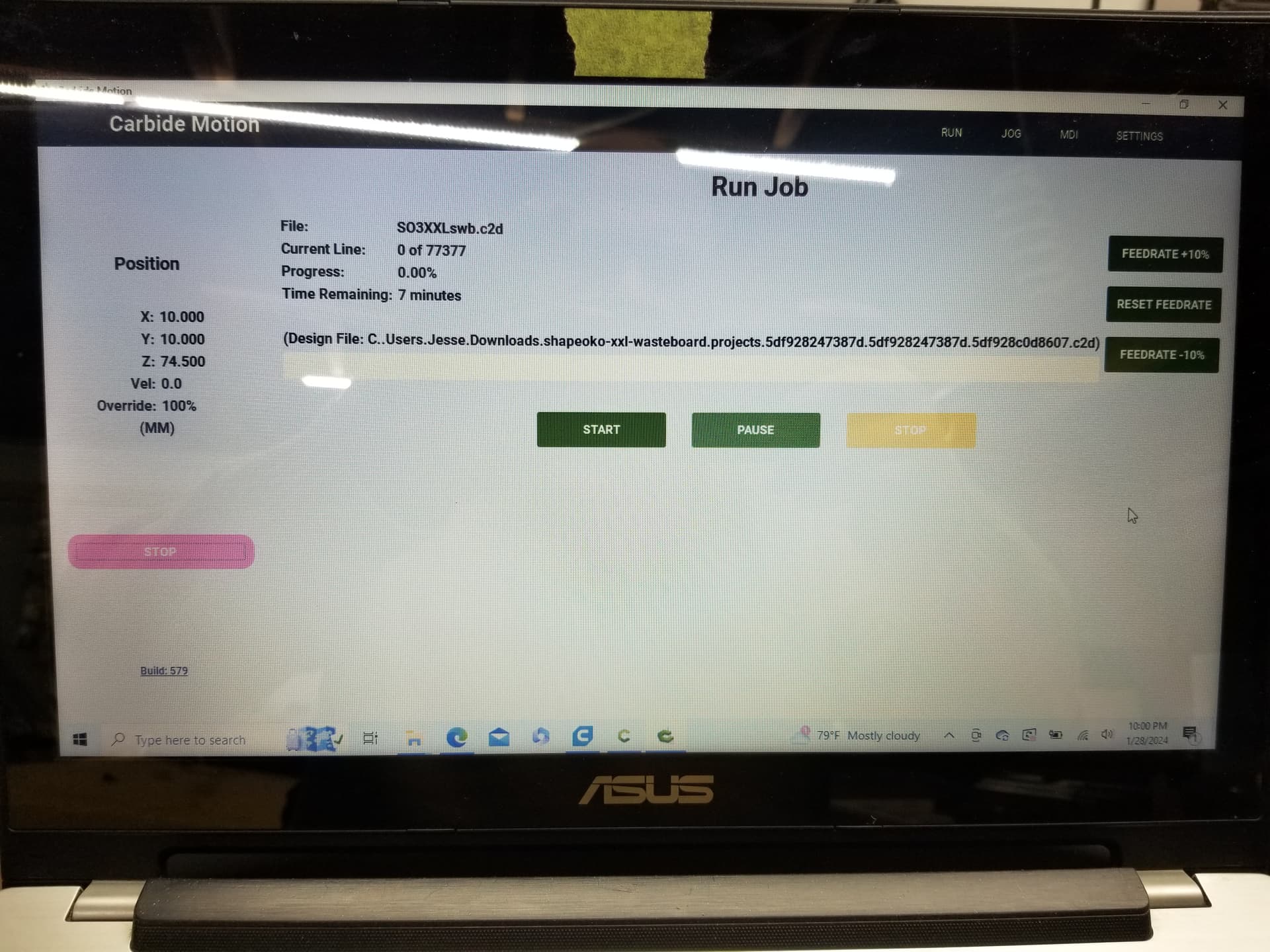
I had the feedrate at 100, with an overstep of 70(from something I had seen on YouTube, on adding the cutter to the tool library).
Also, not sure why it like stuttered for a second at the rear left corner).
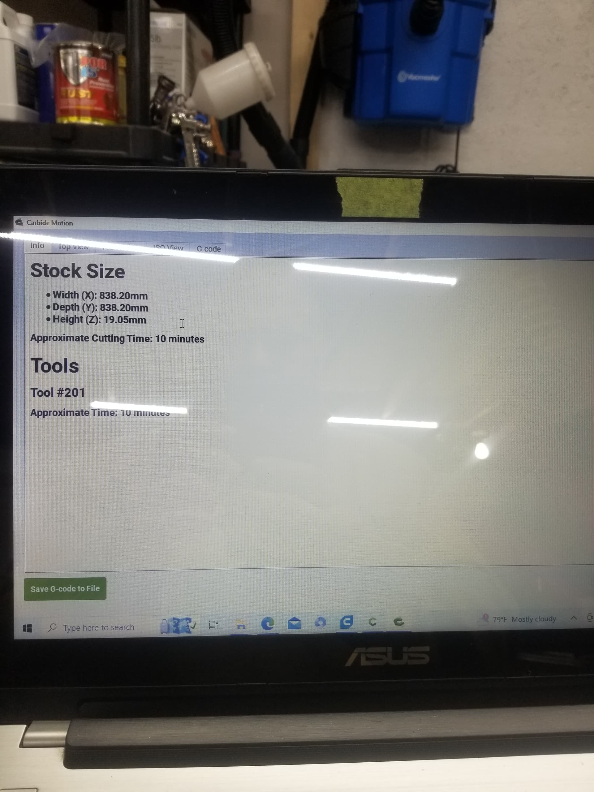
“Done” will continue the process of loading the file to send it to the machine.
“Save to G-code” will extract the G-code from the .c2d file and save it to a local file.
Speed on the router will match the Dial settings — there’s a chart in the manual, or see:
Official chart for Carbide Compact Router:
1: 10,000
        (1.5: 12,000)
2: 14,000
        (2.5: 16,000)
3: 18,000
        (3.5: 20,500)
4: 23,000
        (4.5: 25,000)
5: 27,000
        (5.5: 29,500)
6: 32,000
So, I got my threaded inserts in today, and installed. Thought I’d go ahead and surface it again, and again, on the last pass, at the rear left, it made a shuttering sound. Have any ideas why that may be?
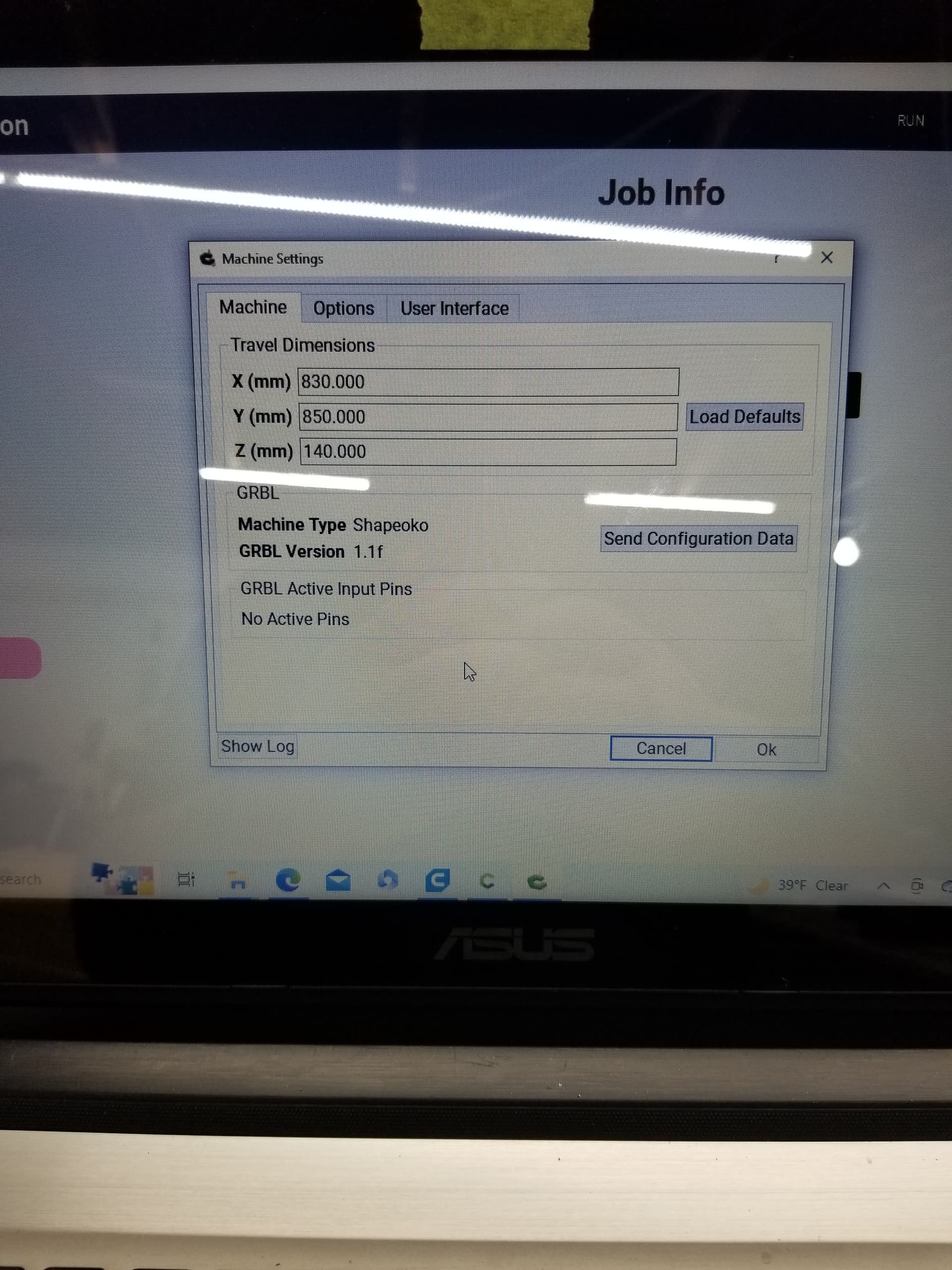
Could you have run out of travel along the back of the Y-axis?
Usually folks enter the full Y-axis dimension w/o considering that includes the overhang cutting area at the front of the machine.
1 Like
I’m not actually sure, to be honest. Don’t know how/where I’d have entered anything for that?
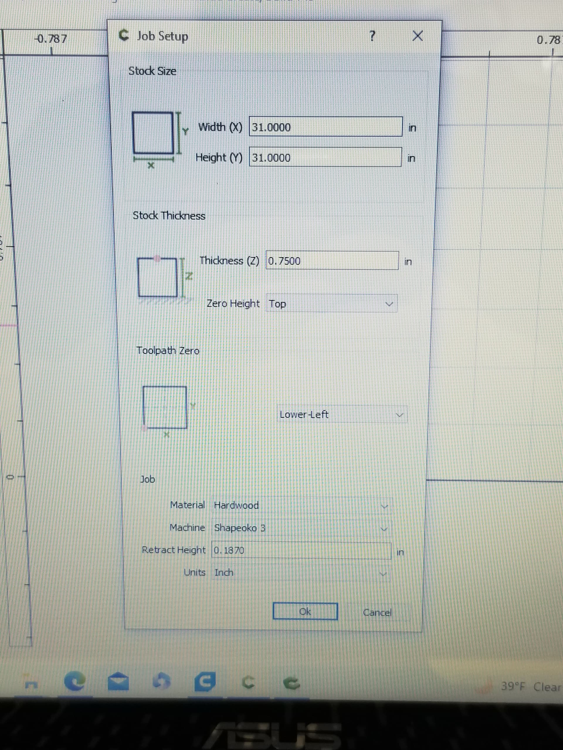
You’re surfacing a 31" deep pocket along the Y-axis on a machine which has a ~32" working area — is your origin out in the overhang cutting area so as to ensure that you don’t run out of Y-axis travel?
See:
1 Like
Possibly, depends on where the origin was set relative to the stock.
That said, usually Carbide Motion warns on this:
https://carbide3d.com/blog/carbide-motion-bounds-checking/
(as noted previously)
Perhaps a hose or something got in the way? Or maybe the noise was something else?
The first time it did it, I wasnt paying attention to my routers power cable, and thought perhaps that was it? Then, as I ran the second time, I made sure nothing was catching, and it still did it.
I’m unsure how to check the origin location you’re refering to?
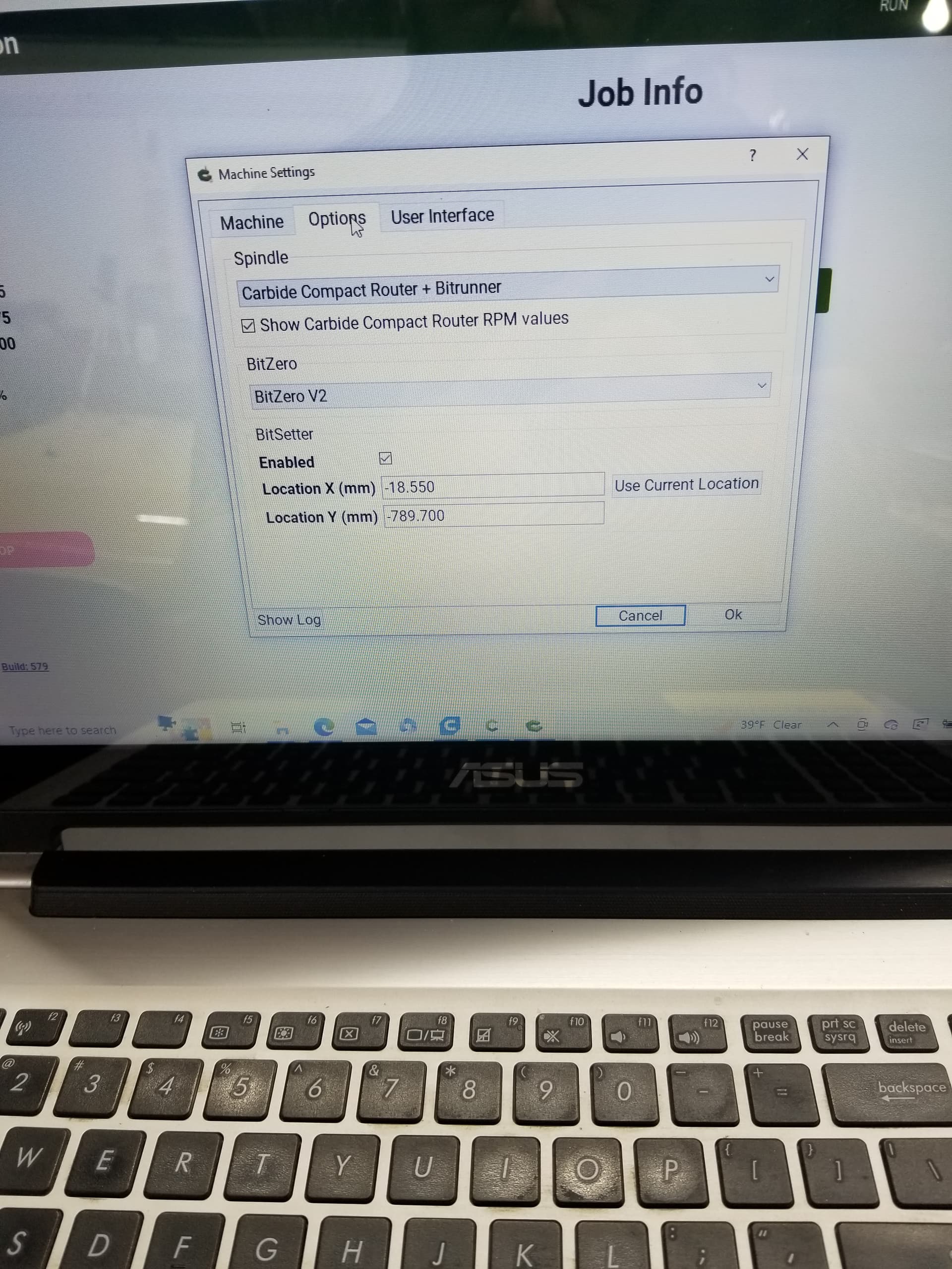
I recieved no warnings either? I am using the upgraded proximity switches provided by Carbide3D as well, maybe I have something set incorrectly there? Granted, when I Initialize the machine, all seems to function properly(goes to rear right, stops when switch lights, comes forward an estimated 10mm, unable to confirm atm, Z axis raises, etc).
Also, I noticed that link stated “Build 616 or later”, and mine says Build 579, I belive(?), if that matters?
On that file you’d modified for me, I had stuck a piece of 3/4 on the machine, and ran it as an “air cut”, and it seemed to be just fine.
Now, since I do need to cut two pieces(left and right), can I select all vectors, mirror it, and not change any other settings and be okay to run it?