Shapeoko 3 XXL help?

Hey group, I’ve probably been the biggest slacker in here, as I’d purchased my Shapeoko 3 XXL in 2019, and still have not used it… I stay busy with work and other hobbies, and am now finally at a point where I need to use the machine.

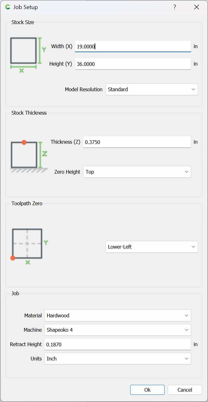
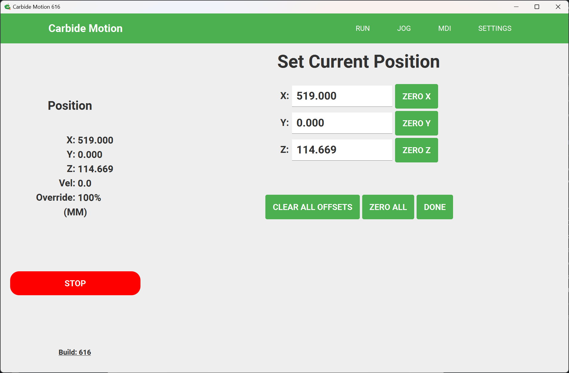
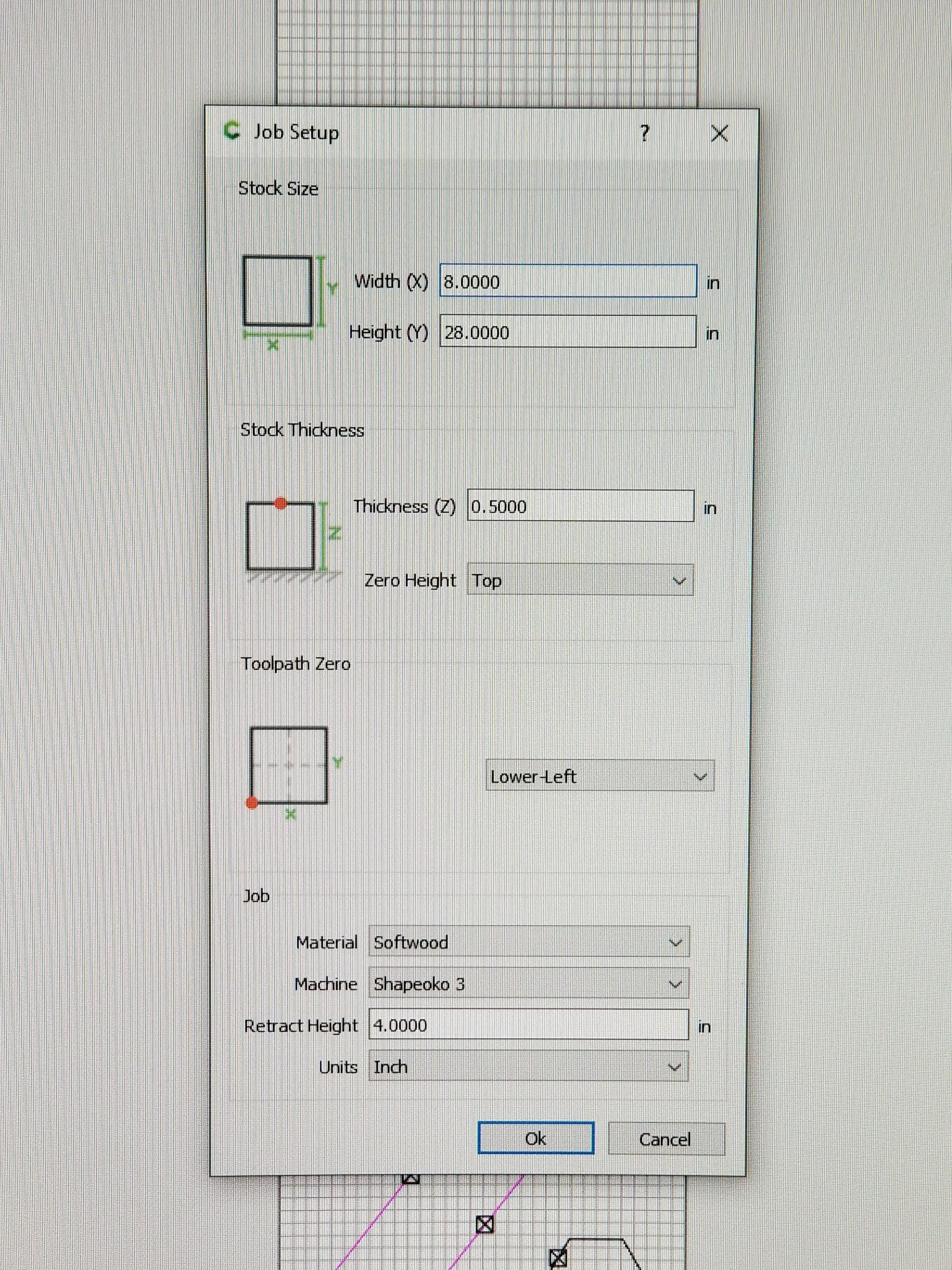
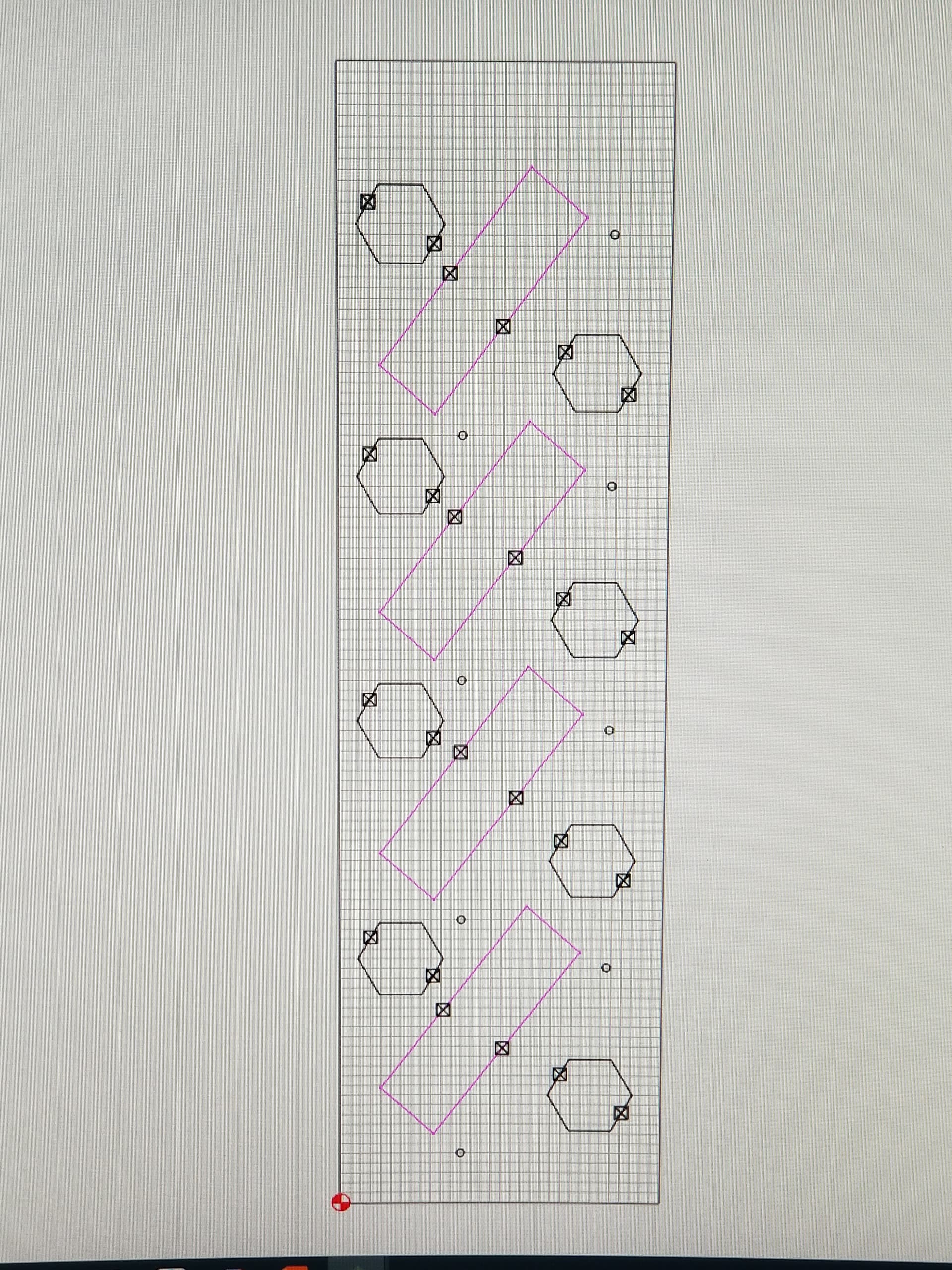
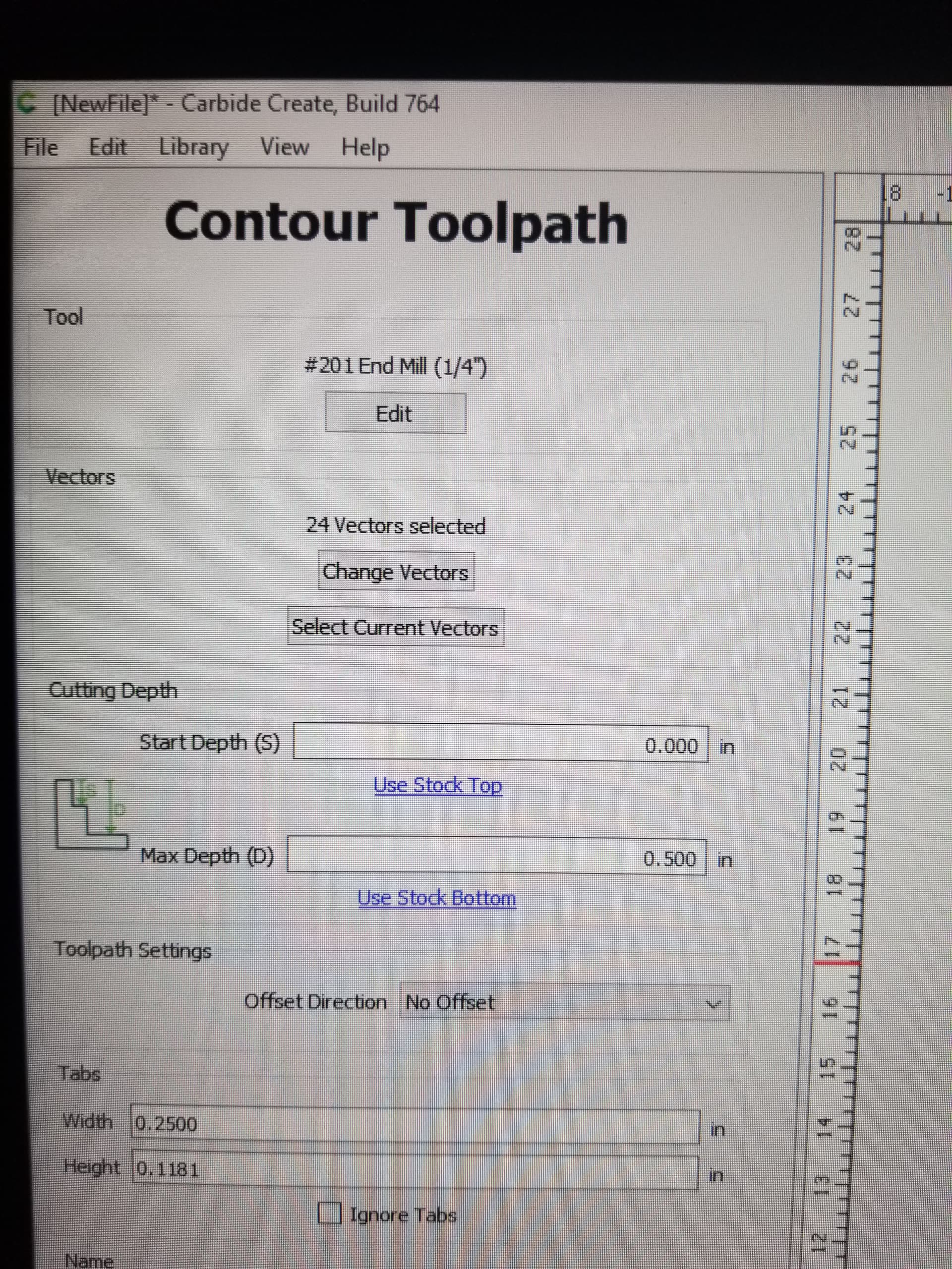
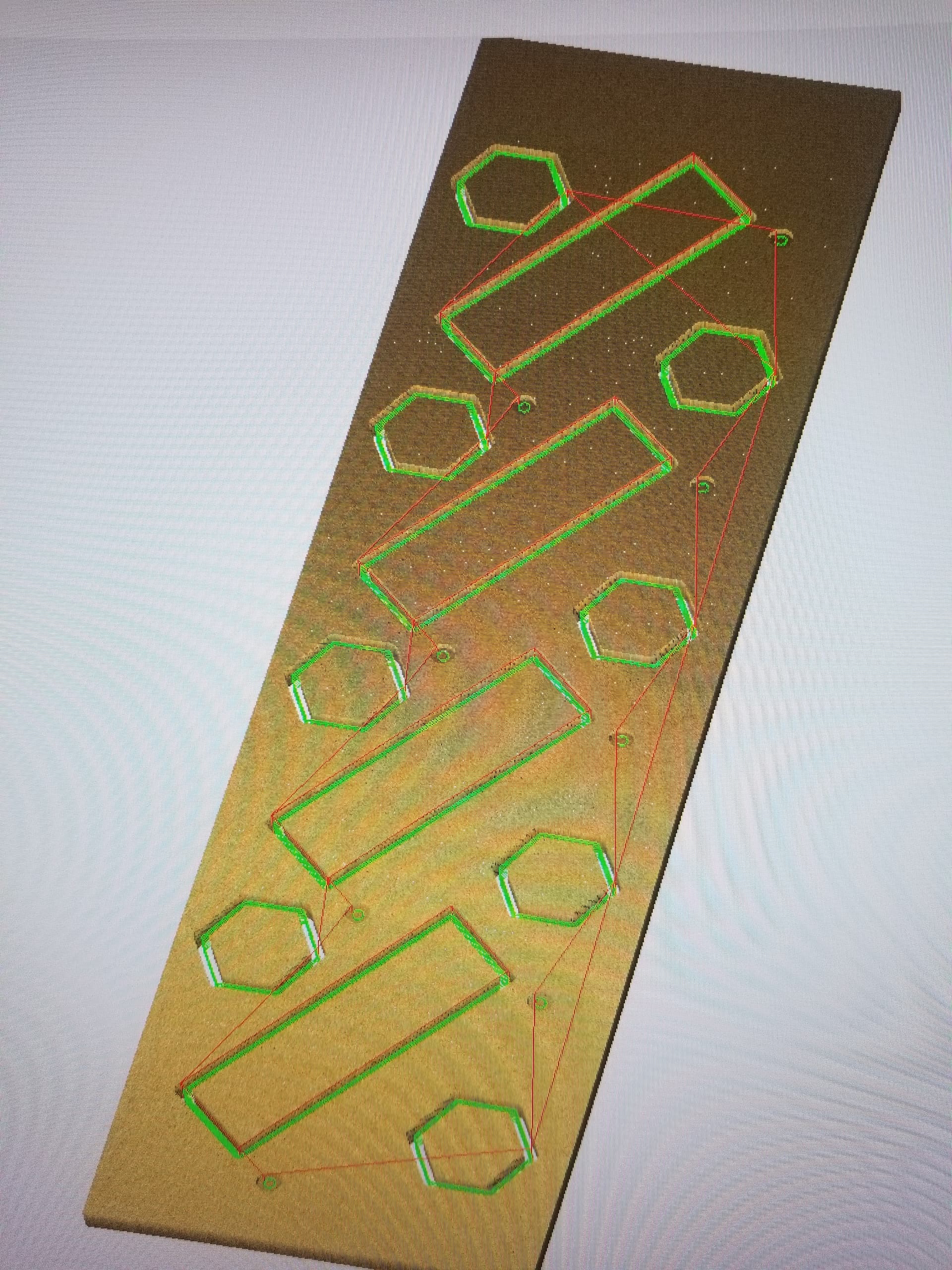
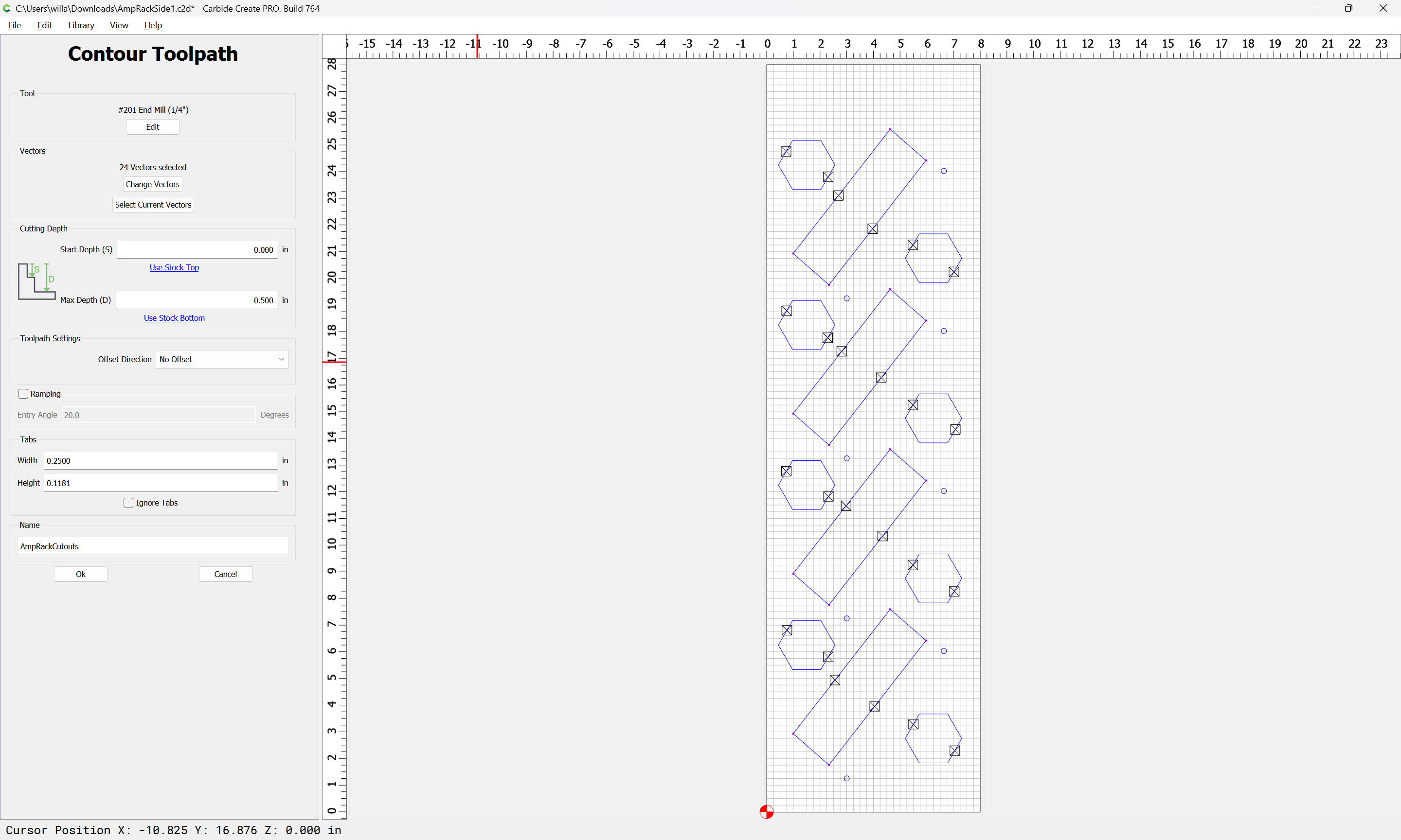
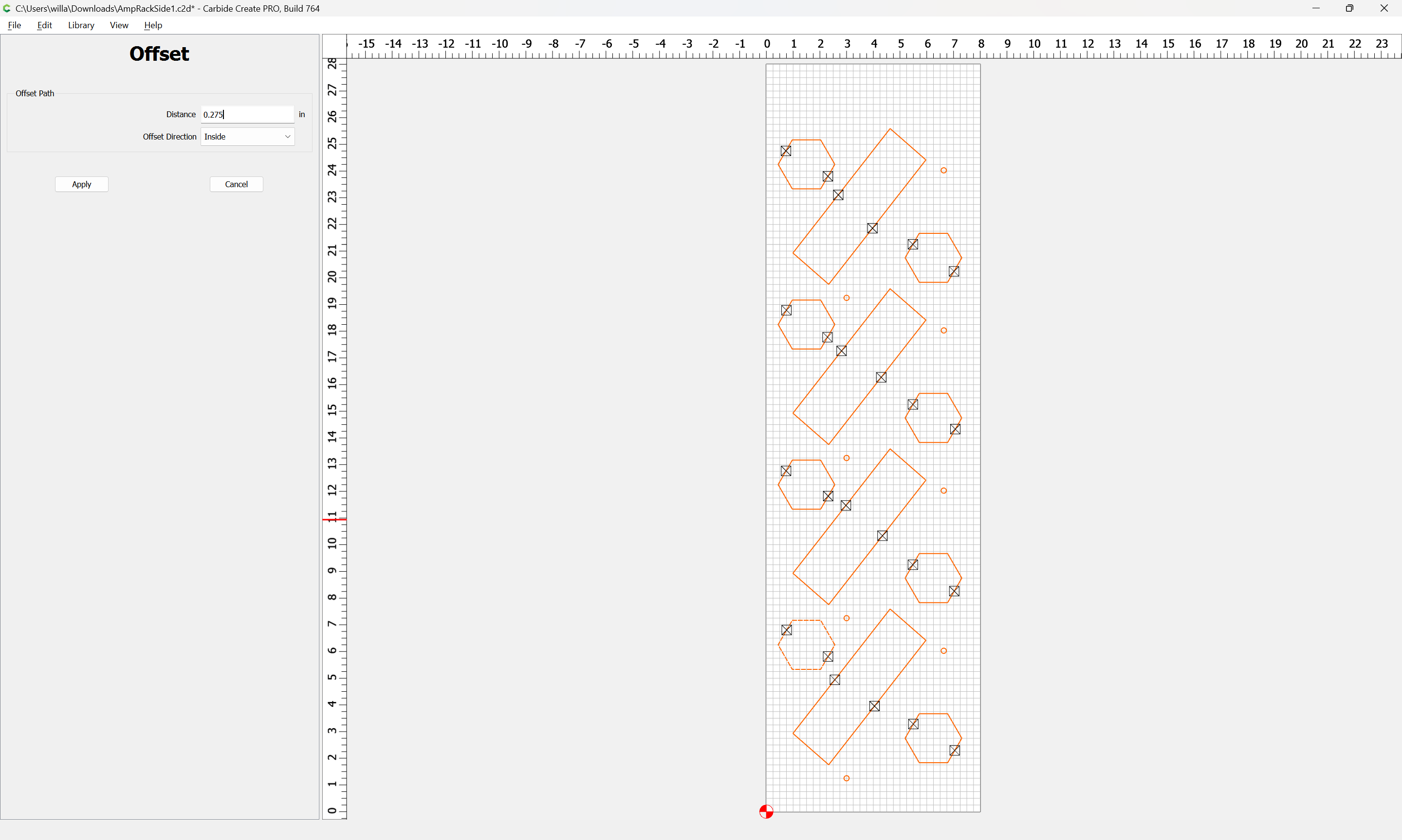
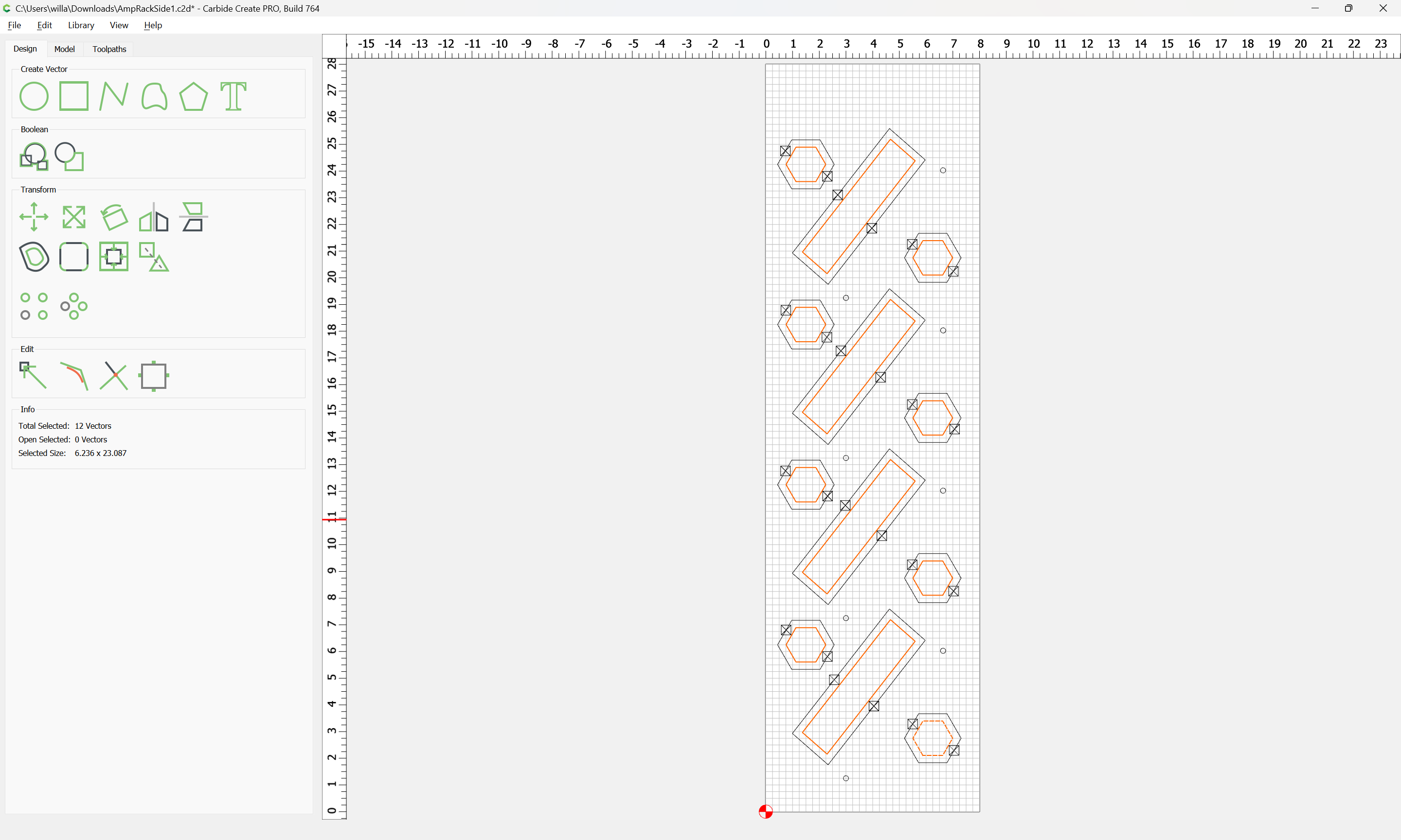
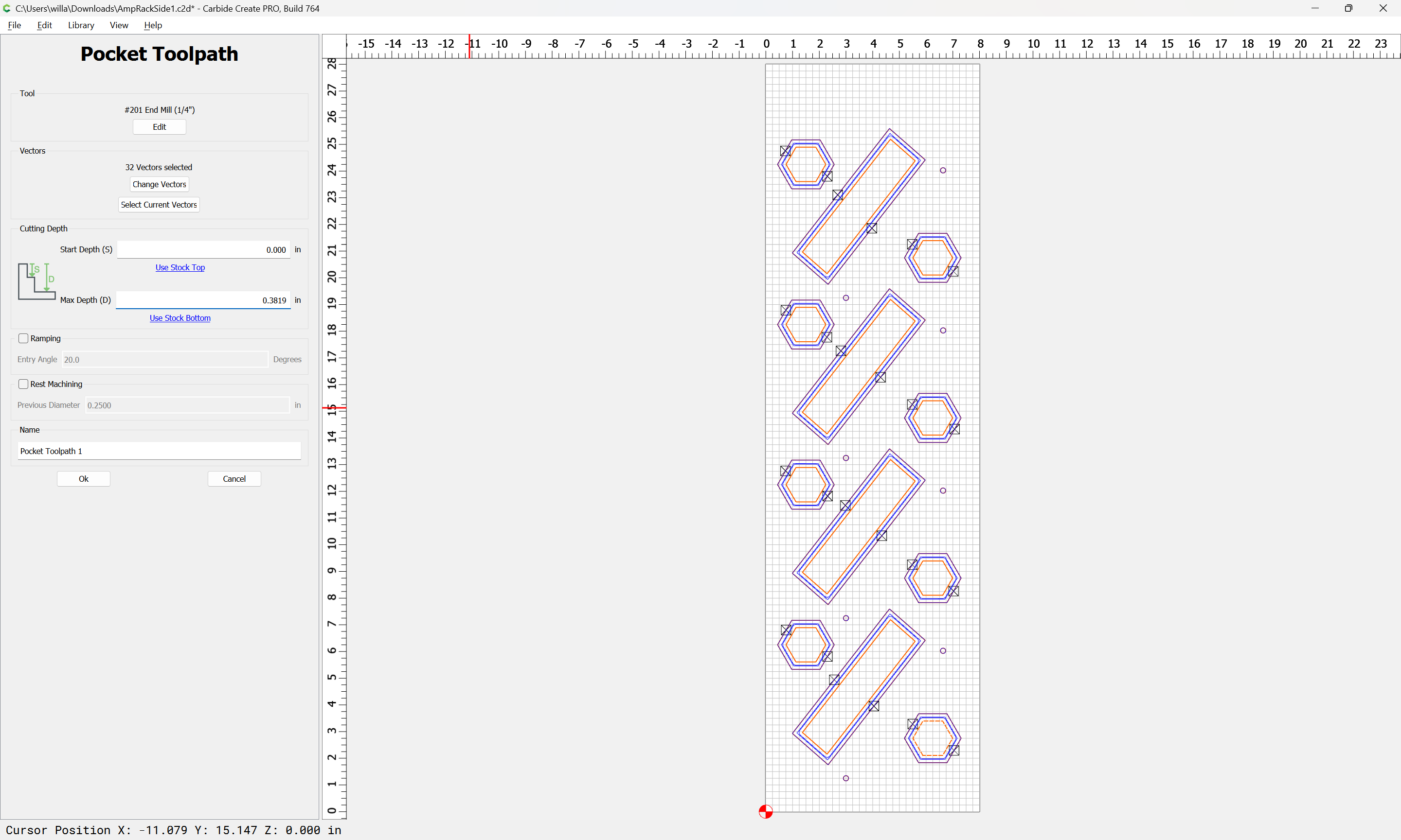
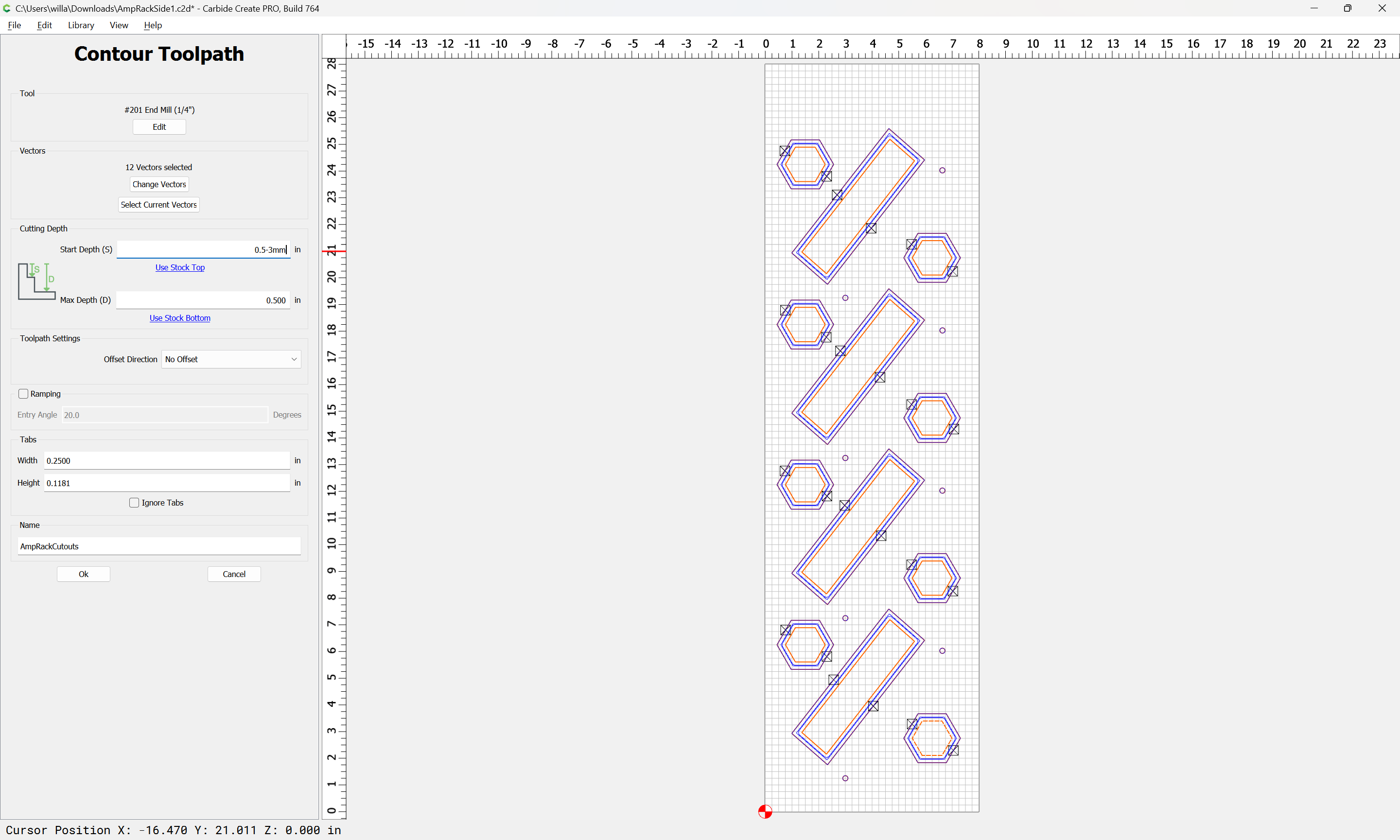
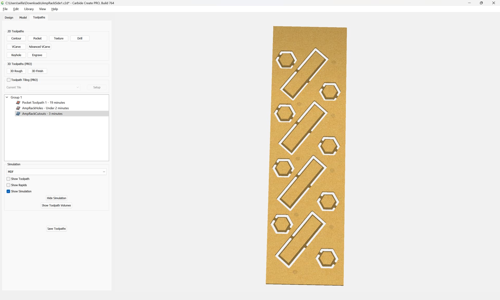
I am well versed in F360 but, just for things I’ve modeled to 3D print, and was not entirely familiar with CC or CM. Well, I didn’t realize how much easier F360 was and recreated my project in CC(which was challenging, lacking various luxuries)and finally have toolpath files saved, and what I’m confused with currently is, on my new desktop, I don’t have CM installed, and now, I don’t know which version I need, or if my XXL upgrades would have any affect on whichever version? I have the BitZero, BitRunner, BitSetter and the HDZ.

I’m beyond stoked(and nervous) to get this cutting, as its been an atrocious amount of idle time.

Thanks for any and all input, in advance!!

Since you are starting fresh, you should probably use the latest Carbide Motion. It supports all your upgrades.

Install CM, connect to the machine, then run the setup wizard (it may start automatically).

Before doing anything very complxs, I highly recommend doing something simple (like, “pocket a circle” simple) on a piece of scrap just to make sure the workflow is going right.

2 Likes

The two possibilities are that your machine has Grbl 0.9 or 1.1 — probably it has 1.1 and you can use the current Carbide Motion as suggested by @mhotchin — if not, it should be possible to upgrade.

For using Fusion 360 to make toolpaths we have a tech note on the setup aspects at:

https://my.carbide3d.com/faq/fusion360/

which hopefully will be a useful guide on getting things set up — there are also videos, and I’m sure the folks at:

will be able to help.

For using Carbide Motion, I’d suggest checking the videos at:

https://my.carbide3d.com/#Projects

as well as the more recent videos at:

and for the accessories: https://my.carbide3d.com/#Accessories

(@KevBarn14 cranks them out faster than I can keep track)

I wrote up a bit on it at:

but that was more a bit of sophistry, I mean, nobody is going to read page after page of:

… click Connect Cutter to connect to your machine.

(and I’m pretty sure no one has read it to its entirety, since there’s a typo in it which I haven’t found time to remember to fix)

Basically, just make sure that each action you take has the expected results and is matched up with the previous actions — when you configure the machine, make sure the software configuration matches the actual hardware, when you set origin relative to the stock, make sure that that matches how the origin is set in the file, &c. If something doesn’t match up, pause, back up, and determine what doesn’t match.

Note that Carbide Motion now has Bounds Checking:

https://carbide3d.com/blog/carbide-motion-bounds-checking/

so you get that calculation in addition to the wireframe G-code preview.

2 Likes

@mhotchin Thanks for the tip on that, and I’ll try the latest version and hopefully it is fine. I figured I’d better play it safe to start and check in here, as I need to do something with this, being so long now.

@WillAdams, I hate to ask but, could you “dumb” down your last paragraph, and elaborate further, please? Thanks!

CNC, like most things, is a sequence of steps — the thing is, you’re turning the execution of some of them over to a robot, one which, aside from homing, doesn’t have any sensors — think of your G-code file as a set of instructions for a blind person to walk through your house w/o a cane — you don’t want them to get hurt, nor to break anything.

So, when you set up a job in Carbide Create:

you are specifying the origin for cutting.

Then, when you set the zero relative to the stock:

that has to match how it is set in the file — if it doesn’t something annoying (the machine will only cut air) or (potentially) disastrous (the machine will try to cut through the material, baseplate, T-track, or clamp).

I tried to record the entire sequence in a couple of posts, see:

and

The big thing is, think in sequence, and consider what the settings from a previous step will require you to do in the future.

The great thing about CNC is that given a properly prepared file, a machine setup which matches the file, and nothing going wrong in the cutting, a part will be made correctly.

The awful thing about CNC is that a part will only be made correctly if the file is prepared properly, the machine set up to match the file, and nothing goes wrong in the cutting.

4 Likes

Alright, thanks!

I am just using the original wasteboard, which I plan to grab a piece of MDF tomorrow, to mount, as a new wasteboard on top, so I can run threaded inserts, and be able to clamp stock down. I had found a link to CutRocket that I’ll try.

I’ll attach photos, of where I am with things now, and I have my machine connected to CM, and I think set up. From my saved CC file(of what I’ve shown below), do I just open the file in CM and it’s ready to cut after using the BitZero?


(Sorry, if I’m confusing or seemingly overthinking this and complicating it for myself.)

Also, I noticed my retract height is wrong, and have changed that accordingly.

Safety/retract height is a balance between low enough to not run out of travel and high enough to clear clamps.

Post your file and notes on how you are securing your stock?

1 Like

As for how I was going to secure, would be blue painter tape and glue.

I was able throw a print from Thingiverse for some Gator clamps at work today, on an SLA machine, just need to just need to get some threaded inserts and hardware(until I figure how to do the T track setup)
AmpRackSide1.c2d (76 KB)

I plan to cut two of these, one mirrored, for a left and right side.
.

Also note, where the holes are, I planned to use those as markers, as I still only have just one #201 that was supplied with the machine, and a Whiteside surfacing cutter.

Did you get a chance to take a look at that file?

I was traveling, so wasn’t able to look at your file until now.

You are cutting a slot just as narrow as the tool to a depth twice the diameter of the tool:

and you are cutting a contour which has no offset, so your geometry will be larger/smaller by the radius of the tool.

Assuming you are cutting holes into the stock, so the significant dimension is the outside one, so my inclination would be:

For the open geometry, Join Vectors:

click “Join Vectors”:

Yes

click away to deselect:

Repeat for all the others, then select everything:

and inset by tool diameter plus 10%:

Select everything and cut as a pocket down to tab height:

and set that as the first toolpath.

If desired, you can edit the Contour toolpath:

to start at the bottom of the previous pocket

This will preview as:

Attached as a v7 file.

AmpRackSide1_v7.c2d (84 KB)

1 Like

No worries on the delayed response, I appreciate the insight! A couple things here, could you explain a bit on what you mean by(or highlight) how I had the slot as narrow and twice the depth of the tool, so I have a better understanding of what I did wrong?

Also, I am uncertain what you mean by open geometry, and by joining vectors, what does that do?

As for the 10%, what is that for? Where you added the Pocket Toolpath, why is that?

I apologize, cause I feel very embarrassed for not fully understanding yet.

A given tool can cut to a given width — you are using a 1/4" wide tool — once a cut gets deeper in its cutting than the diameter of the tool, tooling engagement increases to a point where it can become problematic.

Consider a line:

If you then cut along it:

you will cut a slot:

If you draw the tool and the stock up in profile:

you can see how more of the outline of the tool is engaged as the tool moves deeper into the cut:

Open geometry is geometry which is not joined together so as to define a closed region — this is shown by the open lines/curves being magenta when on the Default layer:

Such open geometry may only be used with Contour toolpaths — all other toolpaths require closed (black) geometry which describes a closed region.

If you wish, the geometry may be joined/closed:

Yes

which will then allow it to be used with any sort of toolpath.

For a Pocket (or other) toolpath which is cutting away the interior region of a closed geometry, the guideline is that it should be at least 10% wider at its narrowest point than the tool used so as to ensure that rounding when generating the toolpaths will admit the tool through said narrow areas.

You may find:

and

helpful (if not, let us know what is not defined/well-explained and we will do our best to make things clearer).

2 Likes

Most all of us have been at that point.
Don’t feel embarrassed for asking for guidance.
Do feel embarrassed when you don’t know and don’t ask and make a mistake anyhow.
WillAdams is an excellent source for information along with several others here.
Start small and simple, get familiar with how the machine moves and works. Create a simple file and see if you can get the machine to do as expected. “Cut Air” a time or two and see how it moves and acts without wasting material. When you can get it to do as expected, secure a piece of stock and give it a try.
Good Luck!!!
MC

3 Likes

Definitely grateful, for such an extraordinarily awesome group!

I’m gonna head over to Menards in a few and get some MDF for my supplemental wasteboard, and I have some scrape pieces aready, that I can practice with.

When trying to “cut air”, would I create a design/toolpath, and leave the start/max depth at zero?(also, that’s a valuable piece of advice, to get comfortable with machine operation, with minimal to no risk!)

What I got from the 10%, is allowing relief for the tool, to not heat up, bind or potentially break, correct?

Both. It’s the pocket toolpath which allows extra room for the tool for physical purposes — the added 10% is for the computer to be sure of being able to calculate things so that the tool doesn’t skip an area.

1 Like

With the supplemental wasteboard attached, do i need to re-zero the machine, to compensate for the -.75 bed, or will my BitZerobcompensate that?

If you previously had the Z-axis origin set at the surface of the MDF table and you habitually re-used it, then it would need to be re-established.

If you are using the BitZero probe to set the origin, then when you probe it will take the new position into account.

1 Like