Making a guitar bridge for Carbide Create Pro

as requested on support…

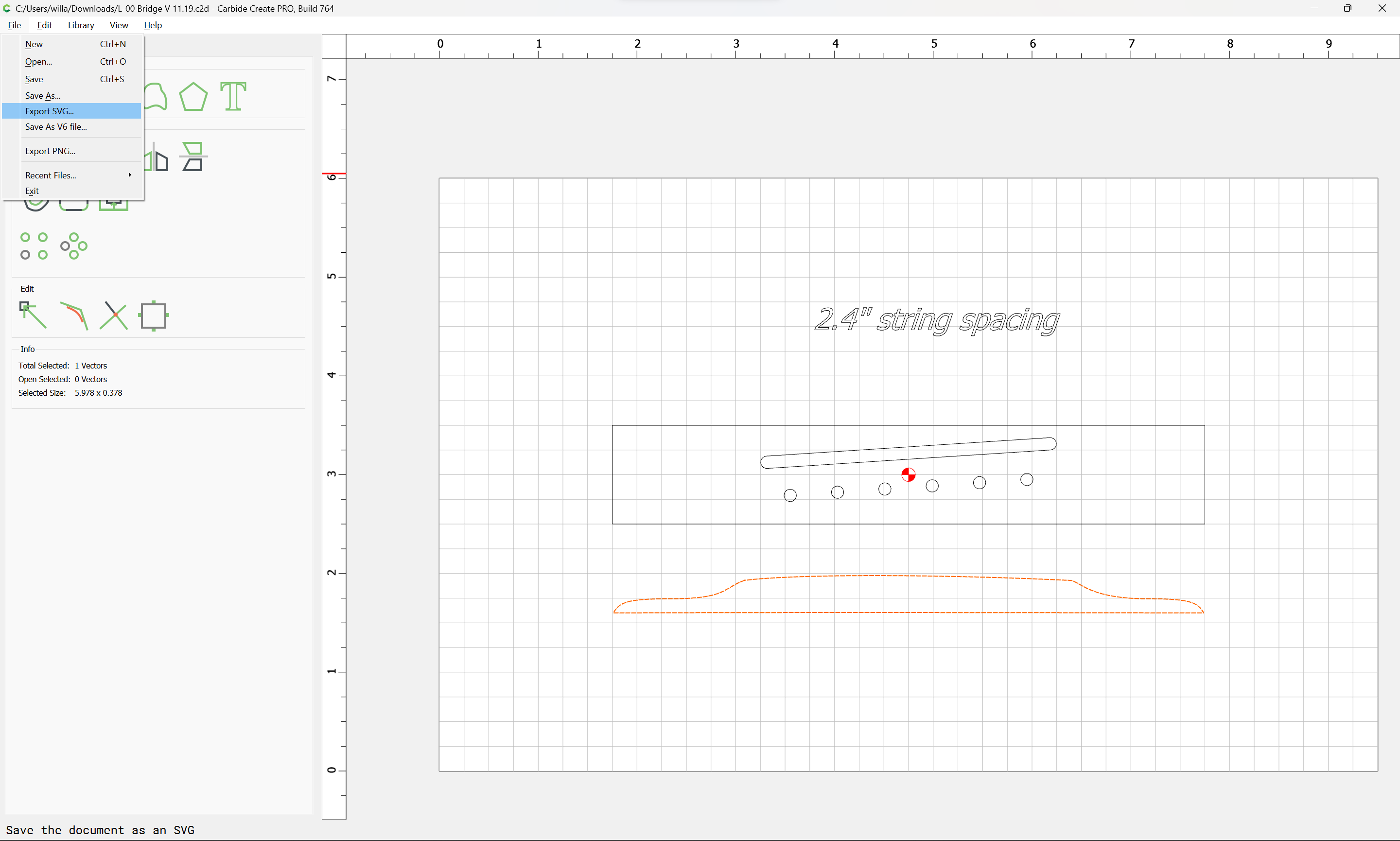
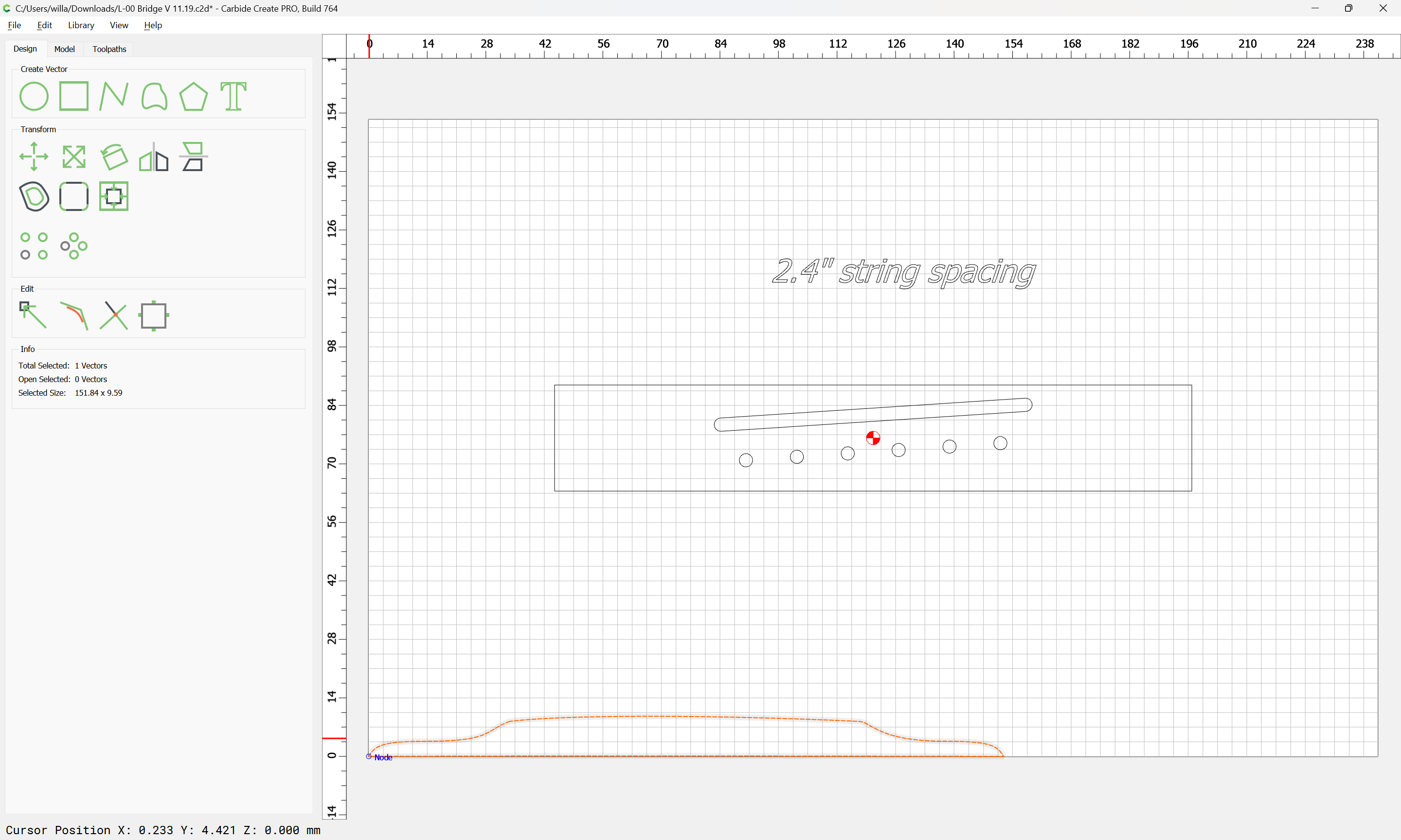
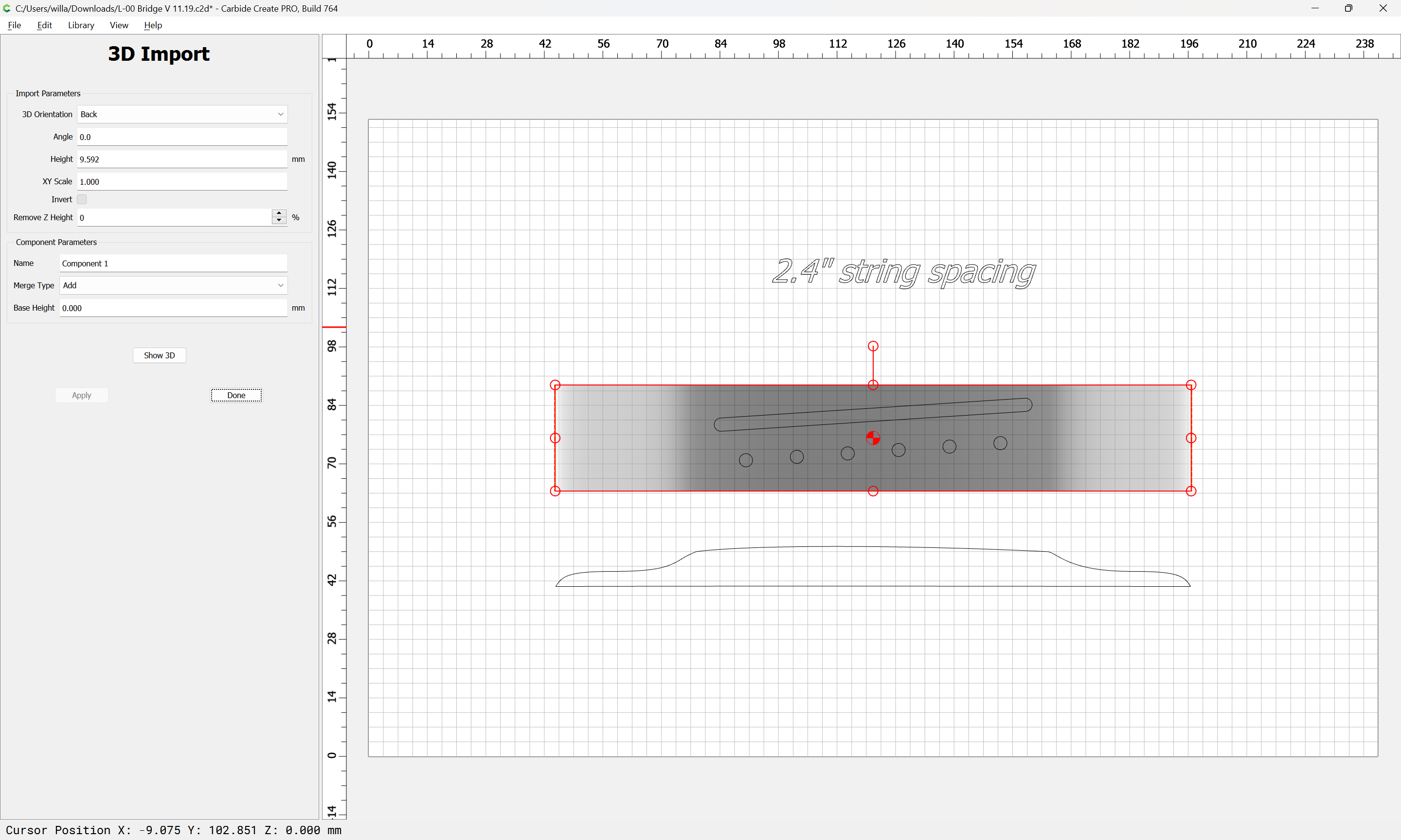
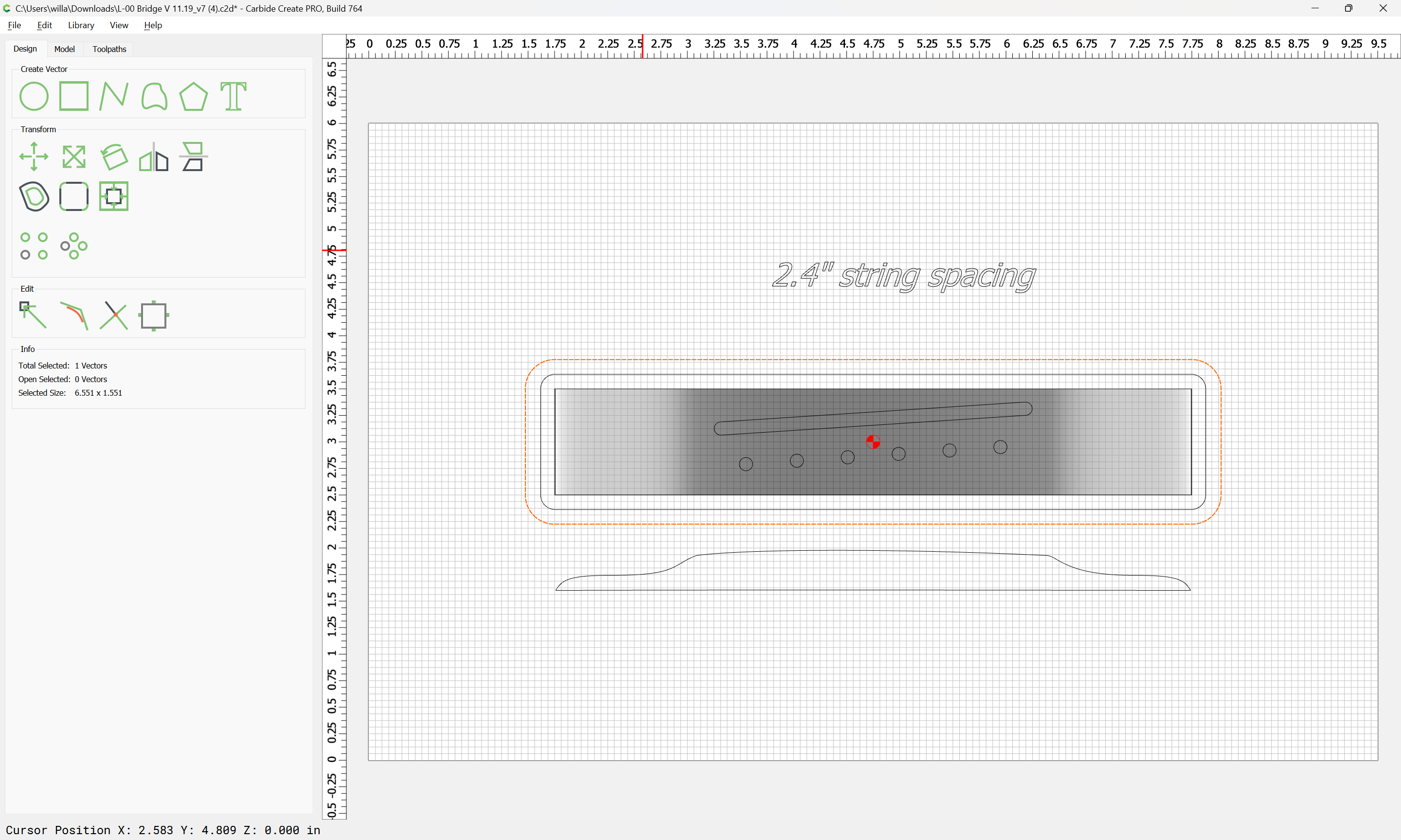
Given a file in Carbide Create which describes a guitar bridge:

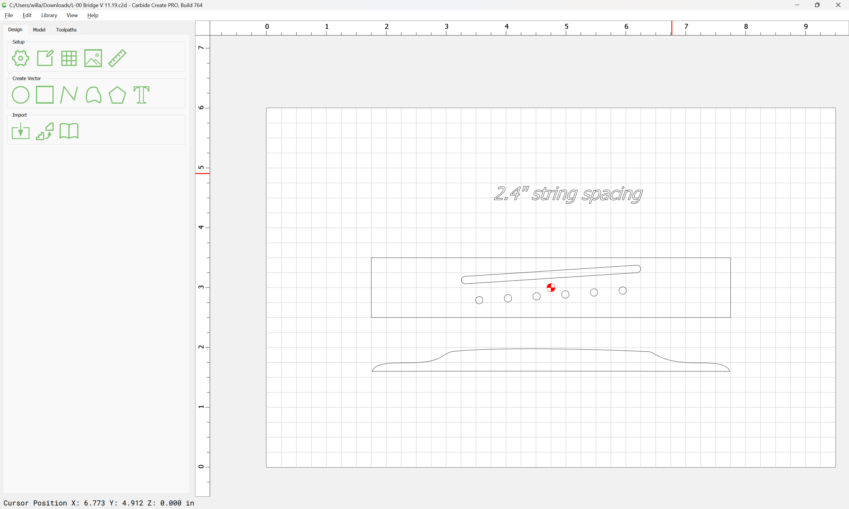
there are a couple of different ways which this part could be made:

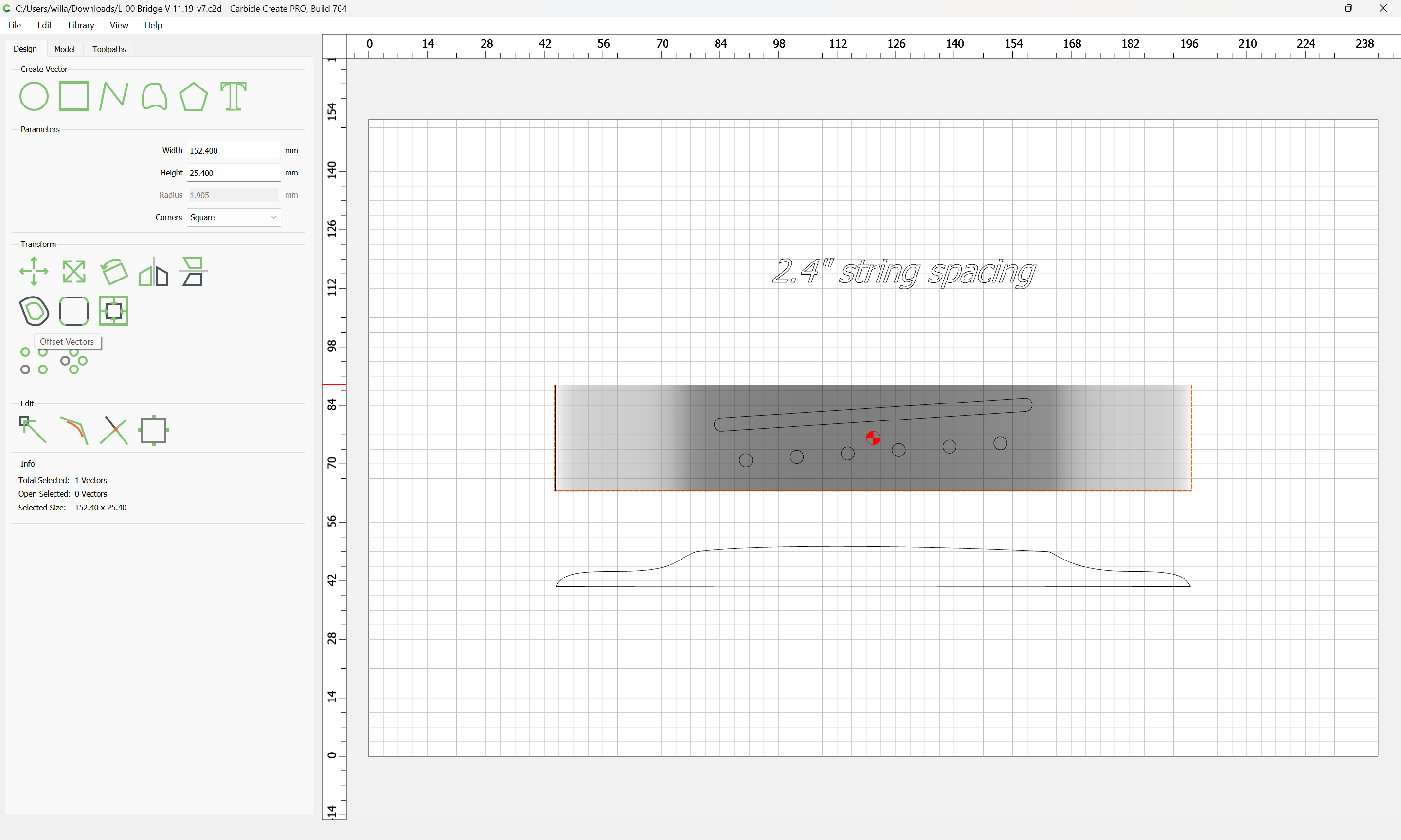
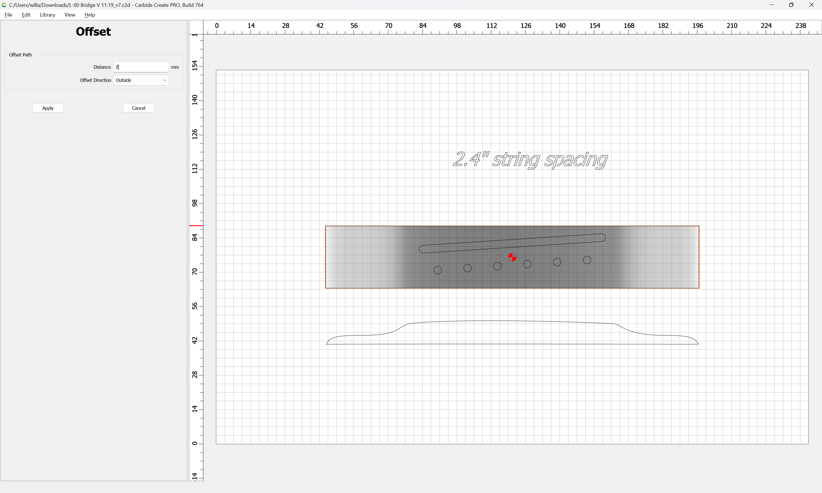
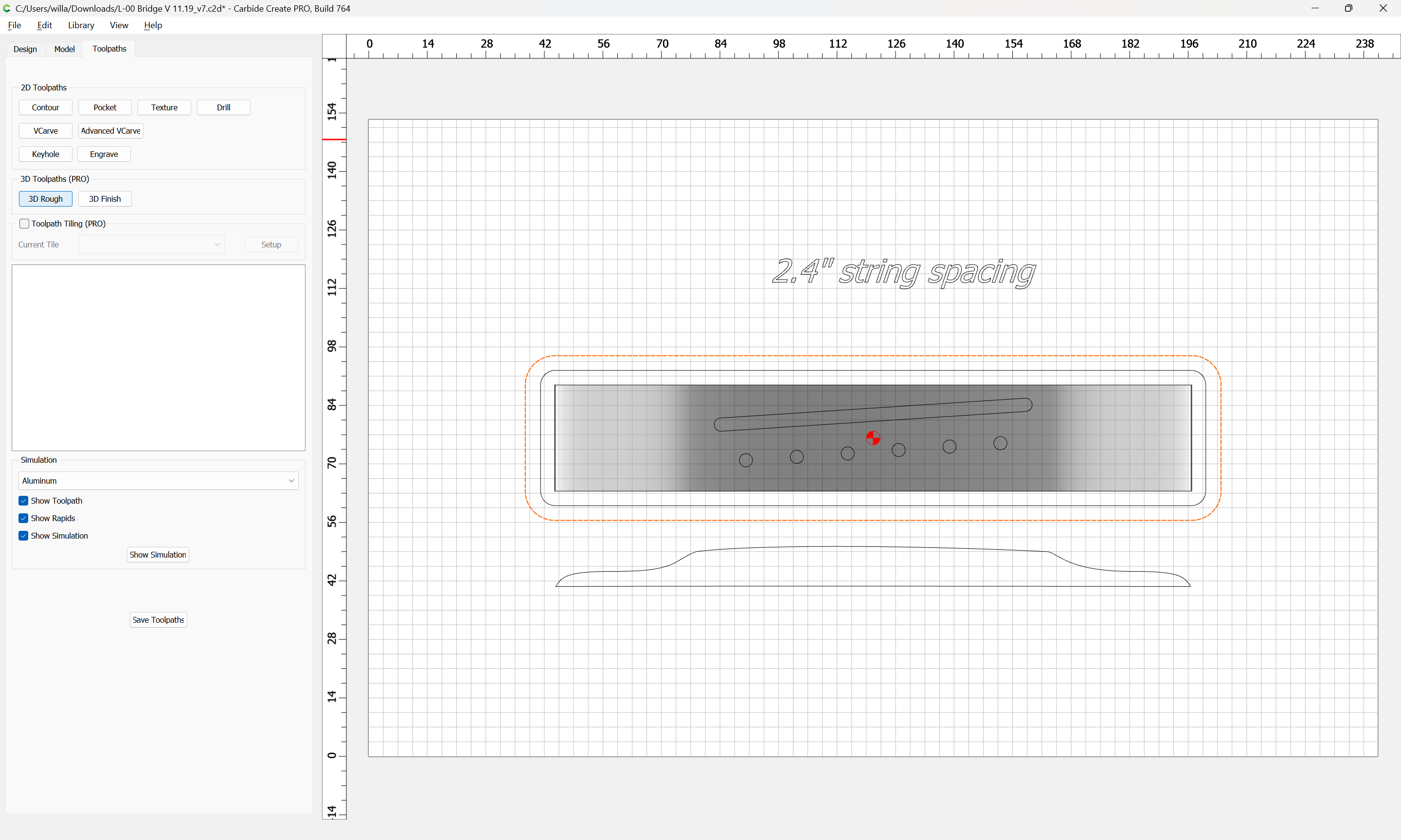
  • draw up contour geometry and assign toolpaths to appropriate depths (note that this does not require Carbide Create Pro): Spoon Possible without CC Pro?

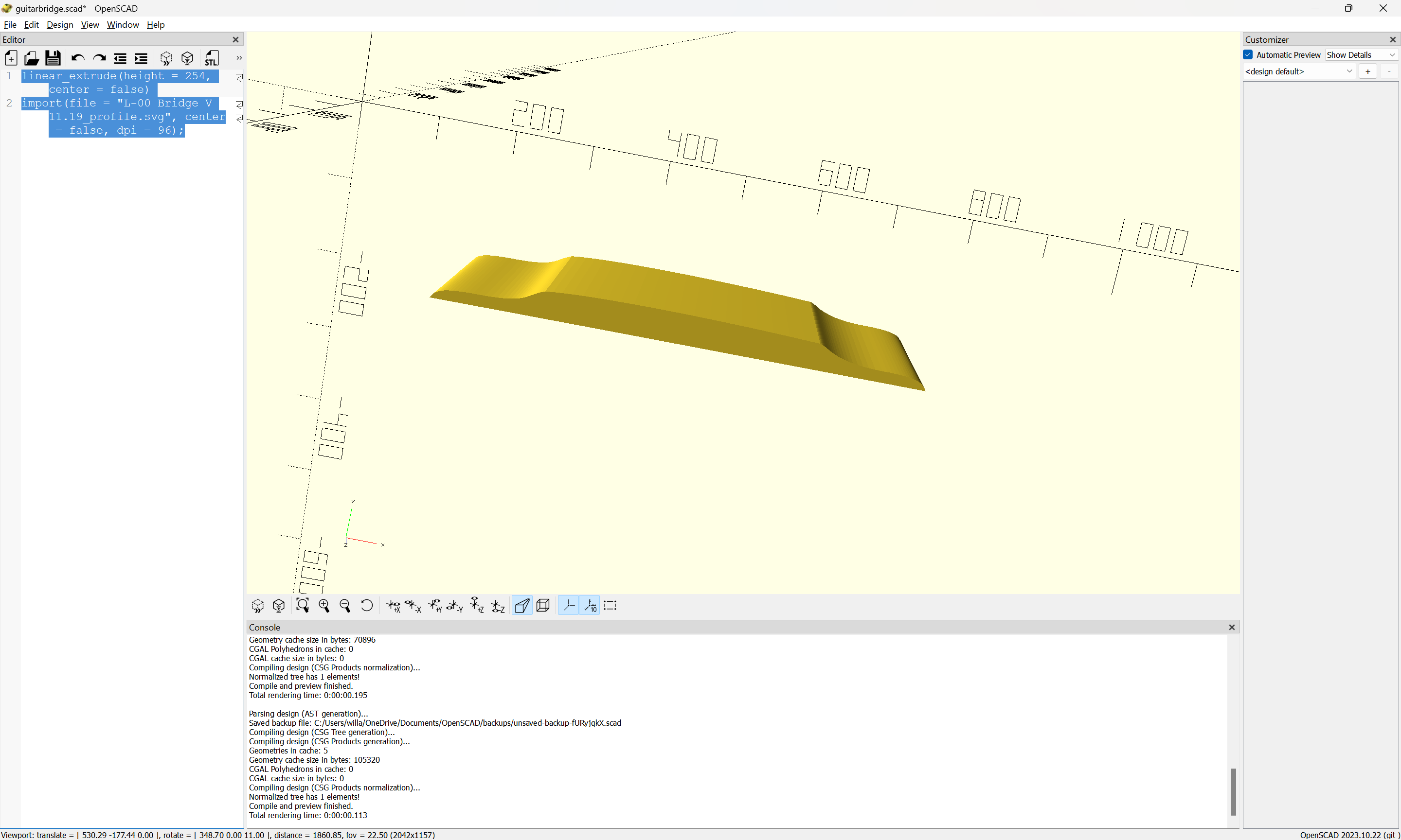
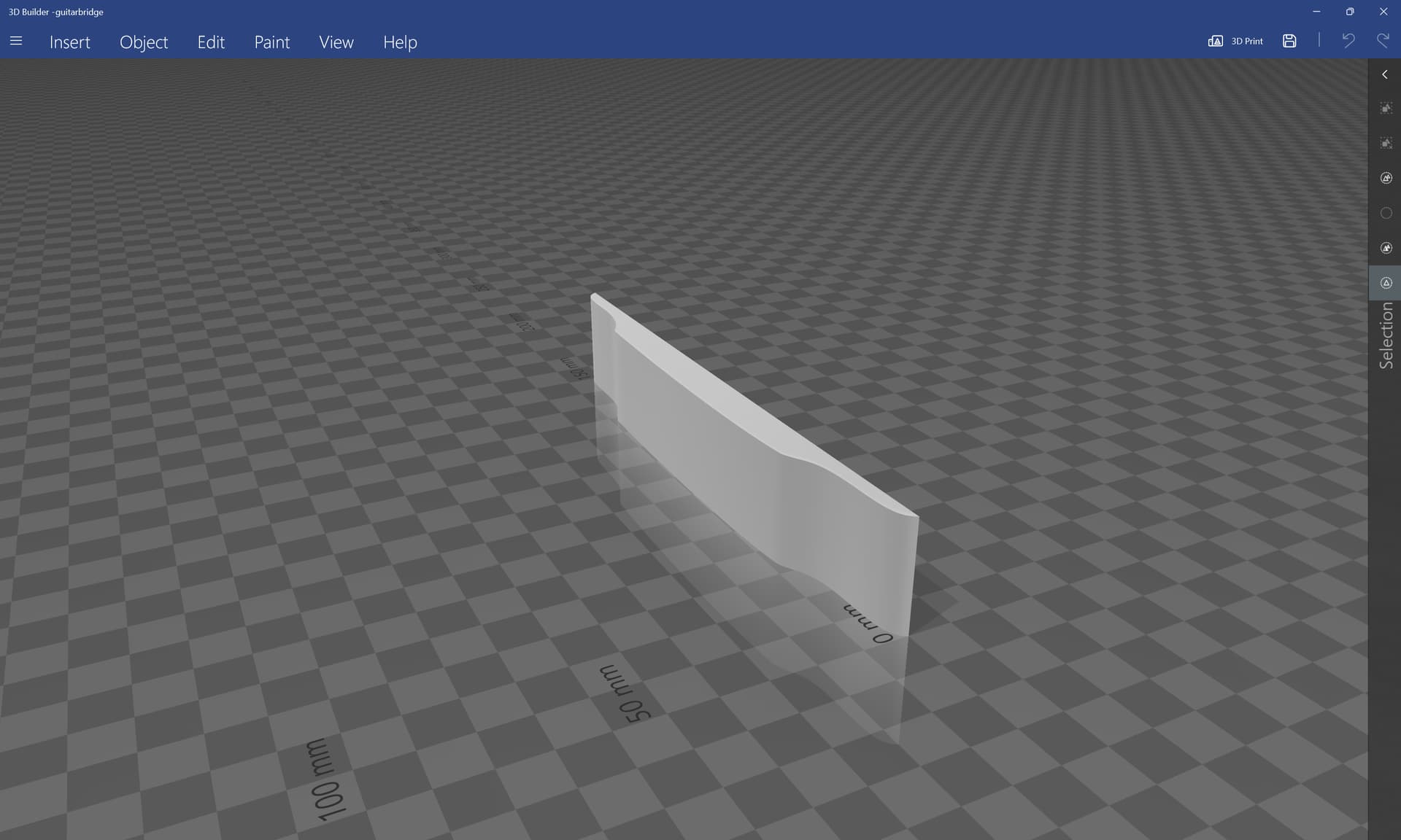
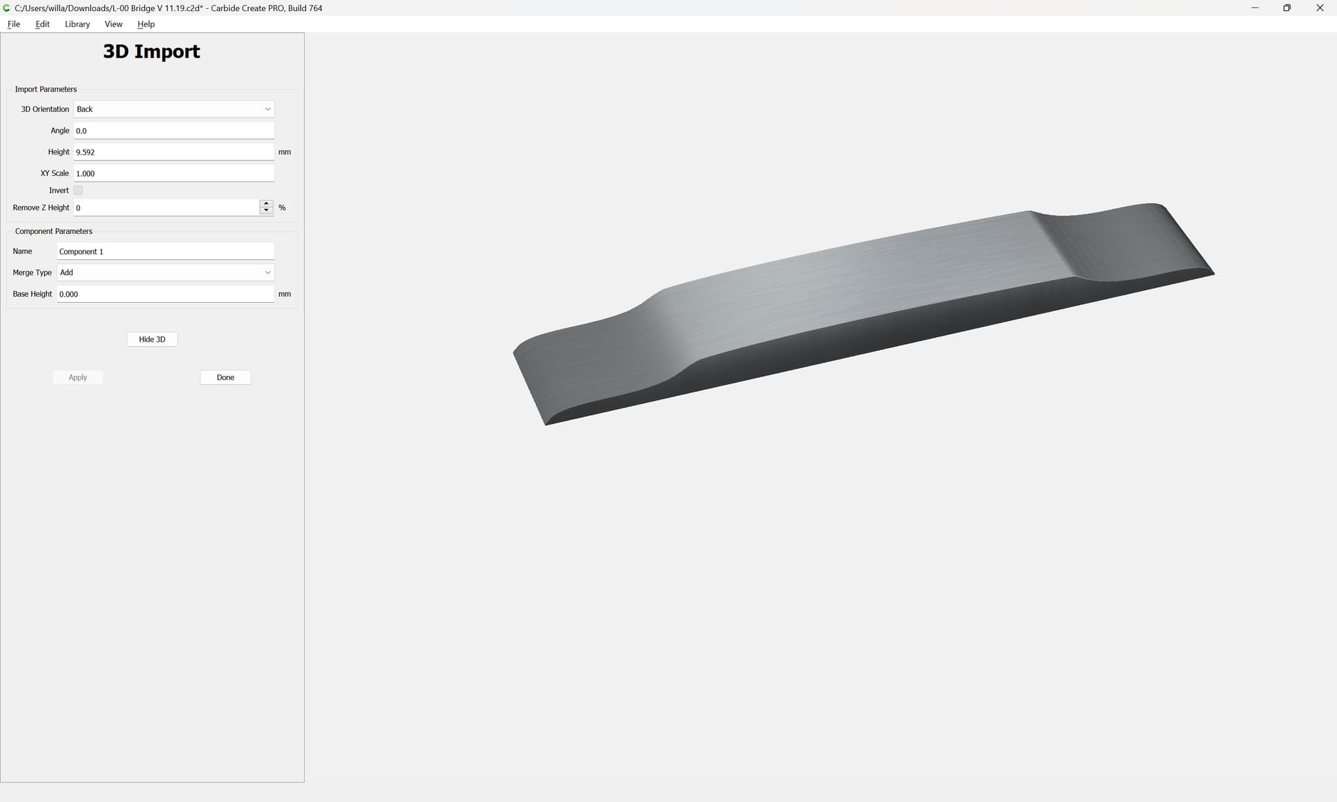
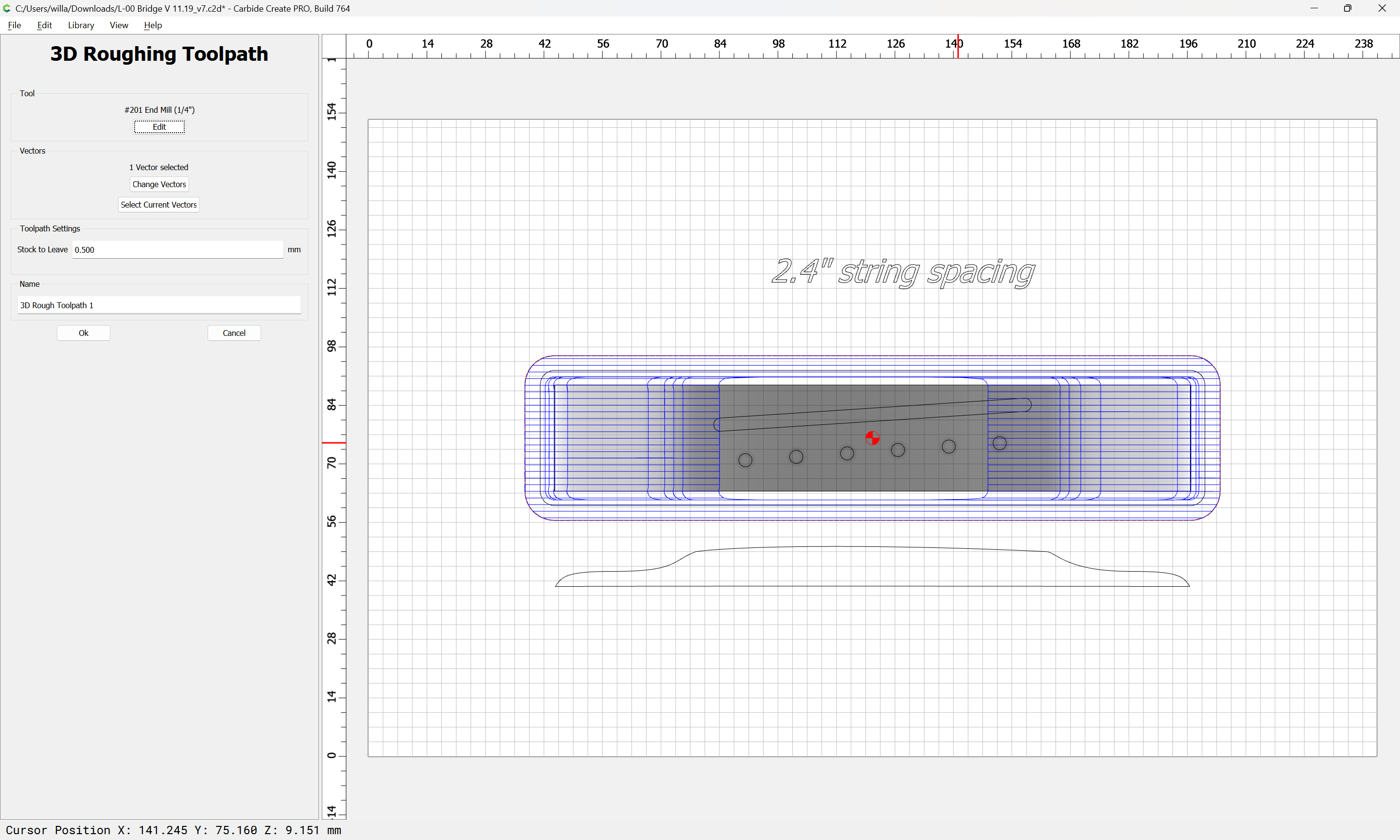
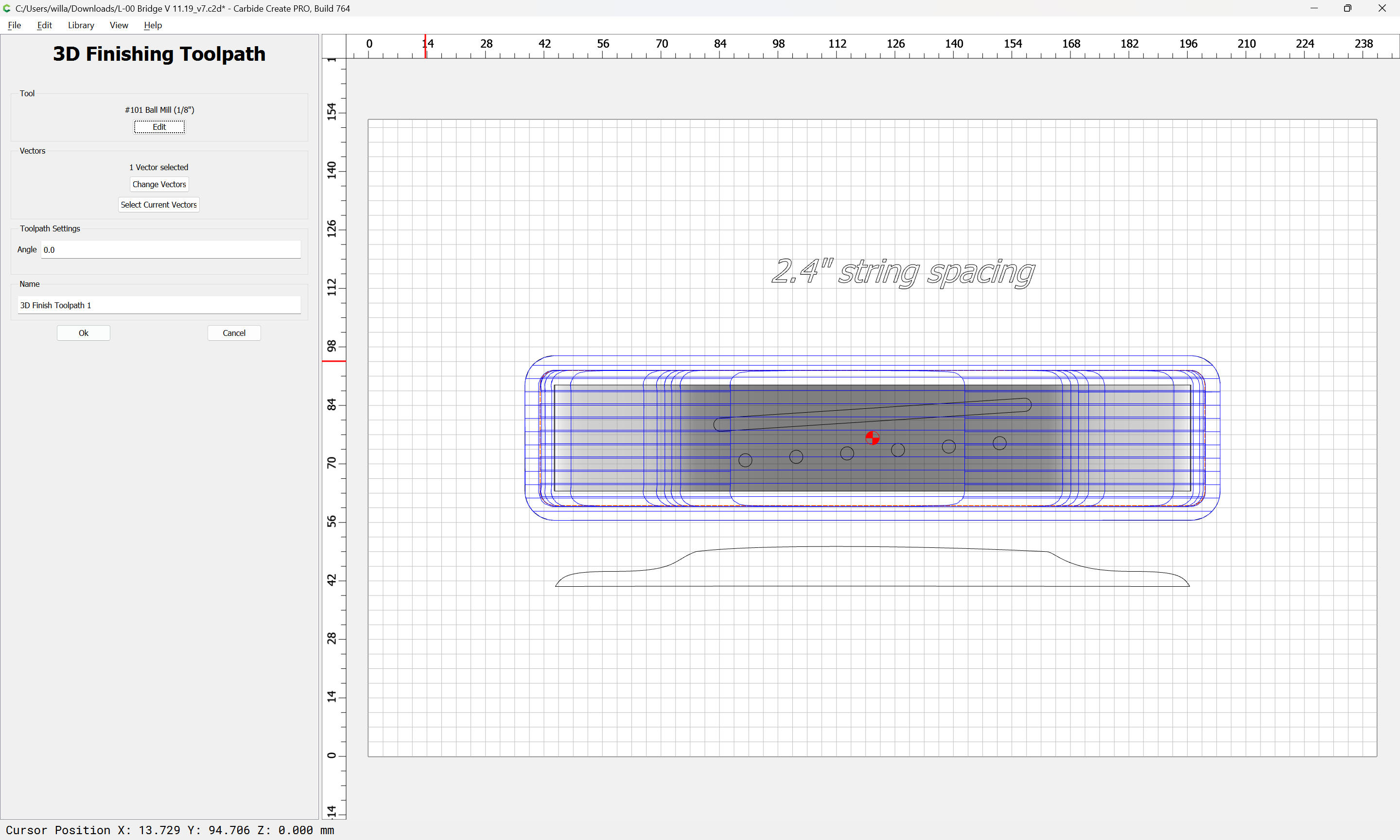
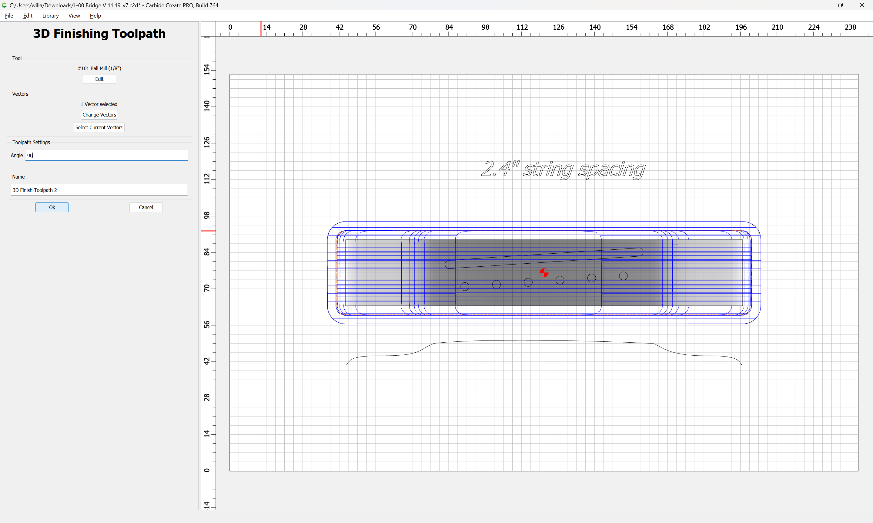
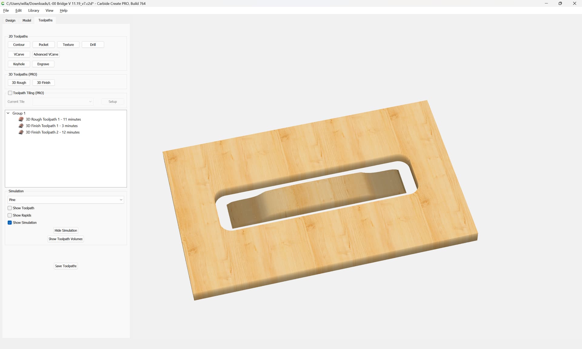
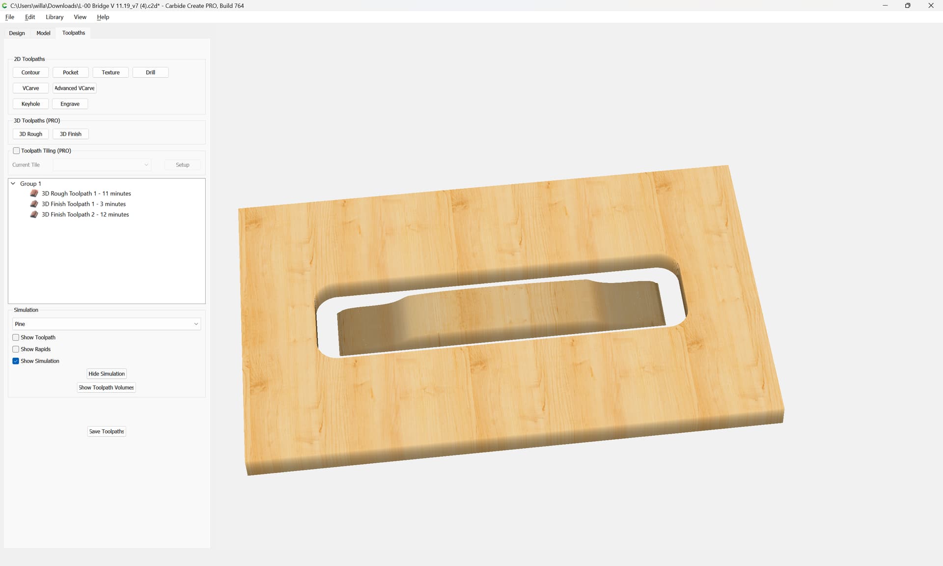
  • model the design in a traditional CAD tool, export it as an STL and then import that STL into Carbide Create Pro and then cut that 3D model using Carbide Create Pro: Instructions on How To 3D Carve using CC V7 Pro - #12 by WillAdams

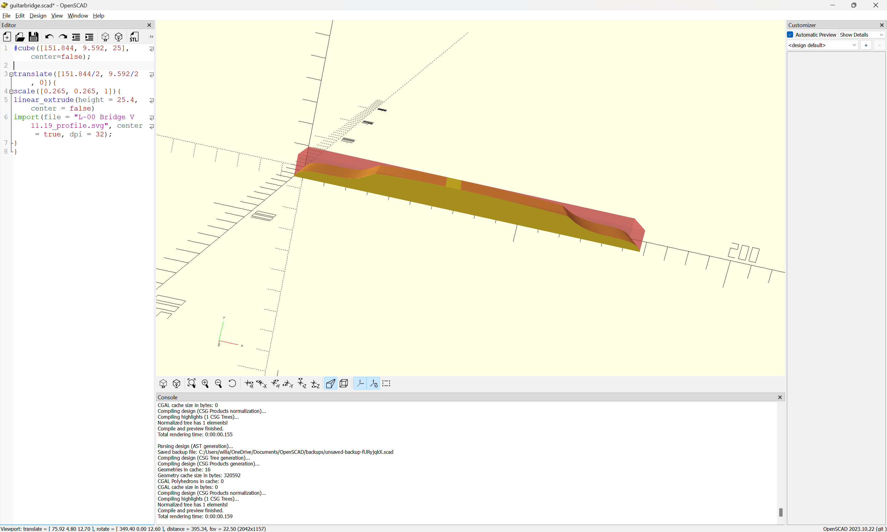
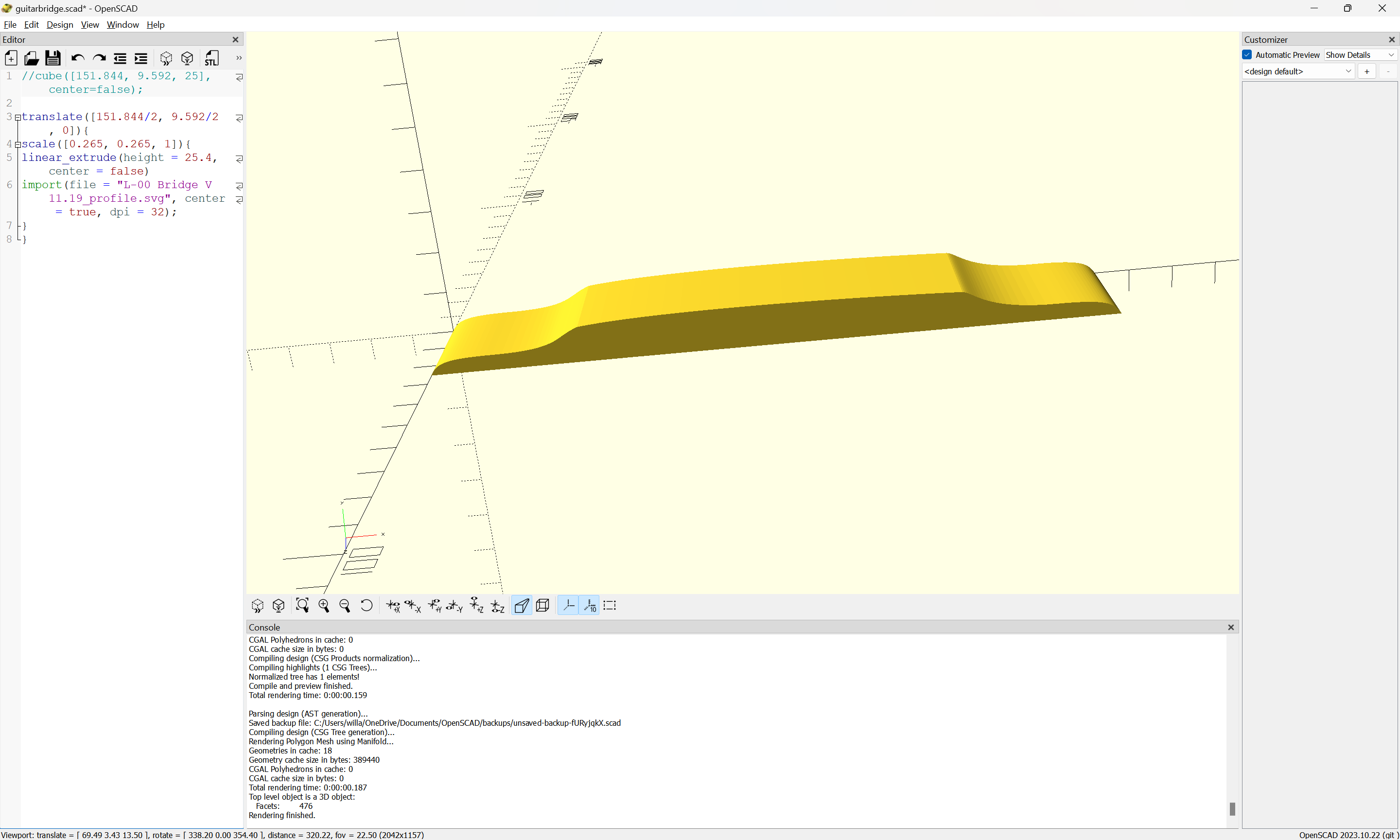
  • translate the profile into a greyscale height/depth map and import that

  • model the design in Carbide Create Pro — this will involve multiple operations and drawing additional geometry — each section of the profile would need geometry to describe the area which would then be modeled so that when all put together would yield that shape.

Here we will look at doing this using opensource tools.

First export the profile geometry as an SVG:

once one has an SVG, as noted at:

https://en.wikibooks.org/wiki/OpenSCAD_User_Manual/SVG_Import

it may be imported into OpenSCAD using the command:

linear_extrude(height = 254, center = false)
import(file = "L-00 Bridge V 11.19_profile.svg", center = false, dpi = 96);

which imports as:

to make things a bit easier, we move it to the origin:

and export over the previous file.

With a bit of experimentation we arrive at:

#cube([151.844, 9.592, 25], center=false);

translate([151.844/2, 9.592/2, 0]){
    scale([0.265, 0.265, 1]){
        linear_extrude(height = 25.4, center = false)
        import(file = "L-00 Bridge V 11.19_profile.svg", center = true, dpi = 32);
    }
}

which we may export as an STL after disabling the cube used for sizing:

which may be imported into Carbide Create Pro:

To make toolpaths we offset to the outside by endmill diameter plus 10%:

and set up 3D toolpaths:

To cut this out, create or download the file in question and open in Carbide Create:

and verify the 3D preview:

select and mark a piece of stock for center and secure it in place on the machine:

power up, connect to, initialize, and allow the machine to measure the tool and then set zero relative to the stock to match how the origin is defined in the file:

Load the file and verify the cut in the G-code preview:

Start Job

change tools as prompted and begin cutting:

Once the roughing toolpath is complete:

change tools as prompted:

and begin the finishing passes:

until one arrives at:

2 Likes

This topic was automatically closed 30 days after the last reply. New replies are no longer allowed.