Instructions on How To 3D Carve using CC V7 Pro

Is there anyone who is able to teach me One-On-One the steps from start to finish so I can create 3D projects? Or perhaps there is already step by step instructions available that I could access.

What sort of design do you wish to do?

Do you wish to import an existing file? (options are DXF/SVG, pixel image as depth map, and STL)

Basically it is:

  • create 3D model — this is pretty much automatic for a pixel image depth map or an STL, for a vector image, select the vector(s) and apply 3D modeling option(s):

Once you have a 3D model, define the region which you wish to apply a 3D toolpath to — in this case we will offset around the model by the diameter of the tool which we wish to use plus ~10%:

Then apply first a roughing toolpath:

Then one or more finishing toolpaths:

Check the 3D preview and adjust as desired.

Hi, thanks for your reply. My thought is to import grayscale files from Google Images to use in CC3D.
After doing the dimension settings of the stock wood is that when I import the grayscale image and center it? Folowing that would I create a box around the stock and create a layer and call it the base? Then would i select the imported image and create another layer subtracting it from the base? Following that would i do the rough followed by the finish paths. Thanks for correcting me as required but I really get confused with the step by step process.

You can’t just use random grayscale images — they have to be depth maps, where dark/light are mapped to height/depth.

Stock size should match the size of the stock which you intend to use for cutting.

Drawn geometry should define regions you wish to work with — for example, you could put a circle in an area, then import a pixel image into it and the pixel image will be centered in the area so defined.

You can add or subtract in any order which makes sense for your design.

If you’ll post an image you wish to work w/ or a .c2d file which you are having trouble w/ we will do our best to assist.

This is what i would like to create??

That image should work well.

Have you tried importing that into Carbide Create as a 3D model and drawing around it and defining toolpaths?

No I have not. Do I import the design and then draw a circle around it? I would then “add” to the circle so it creates a bowl effect and then “subtract” the design within the bowl. If correct do i use ROUND for both shapes? Sorry for my lack of knowledge.

Are you trying to emboss (raise) this shape onto the bottom of a bowl? Or engrave (carved out)?

Give a description of the result you are looking for, and some dimensions would also help. (dia, size of fleur de lis, heights)

I think, in order to use the shape in the center you would need to fill the outside with black. Otherwise the white in the center & the white around the edge will be the same height.

Here it is on a coin / coaster

image

1 Like

I have piece of maple 8.5 inches wide by 13 inches high and 1 inch thick. I would like to fill as much of the stock as I can so perhaps a bowl 7 inches in diameter and .6 inches deep. The fluer de lis to fit inside bowl embossed. Perhaps 5.5 inches wide and .4 inches high?? I dont understand your point of filling the outside with black?? Sorry for my ignorance.

Is it possible to just emboss the fluer de lis onto the stock without a bowl. If so how would i format that??

If you leave the outside white it comes in at the same height as the whitest part of the design

You can cut it by itself, yes. I assume you just mean on a flat surface. You still need to create geometry to define the rest of the workpiece.

Here it is modeled into the bowl you describe. 8" outside dia. 7" bowl shape. Fleur de lis adjusted to fit.
I created the outside shape as a flat 1" component selecting the outside circle.
Then create the inside bowl shape by subtracting a 0.6" scaled height round component.
Then added the image at 0.1 high, and adjusted the scale factor until it looked nice

3 Likes

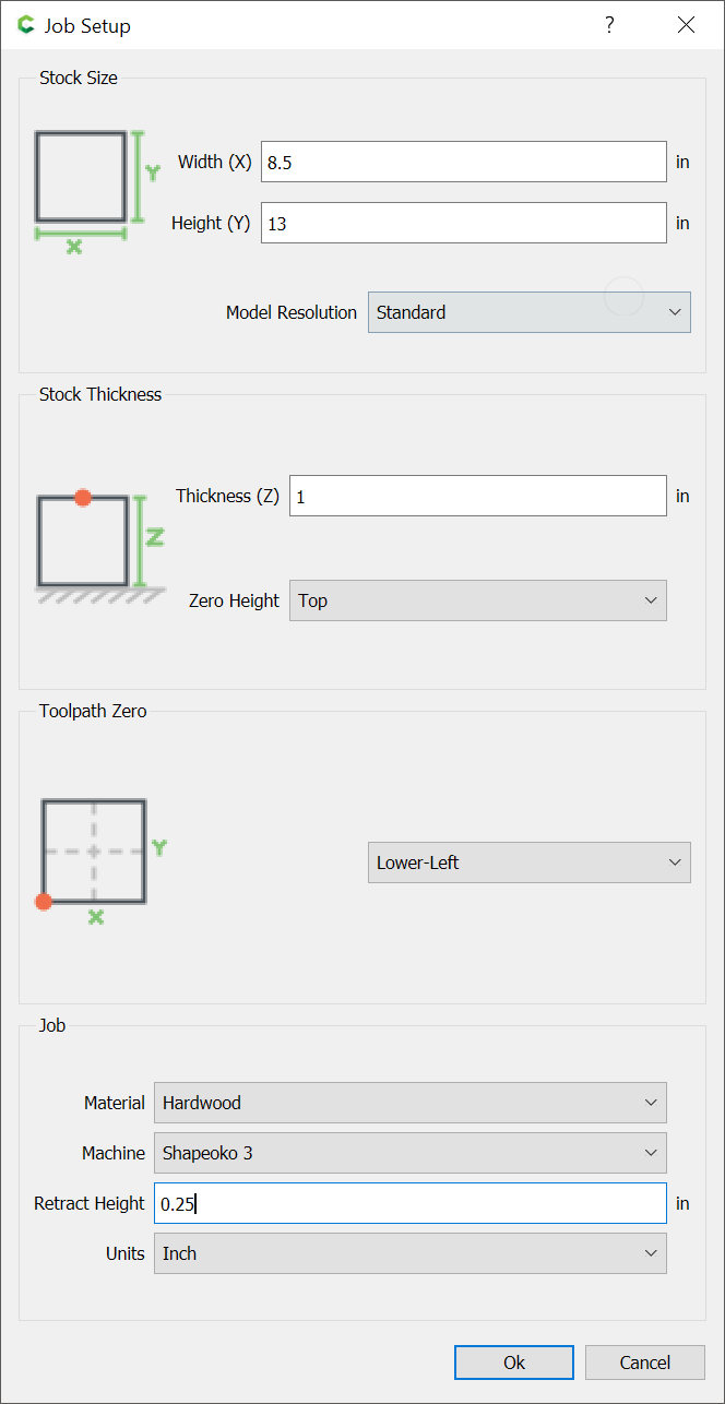
First, configure the stock:

Draw in the geometry for the bowl and place as desired:

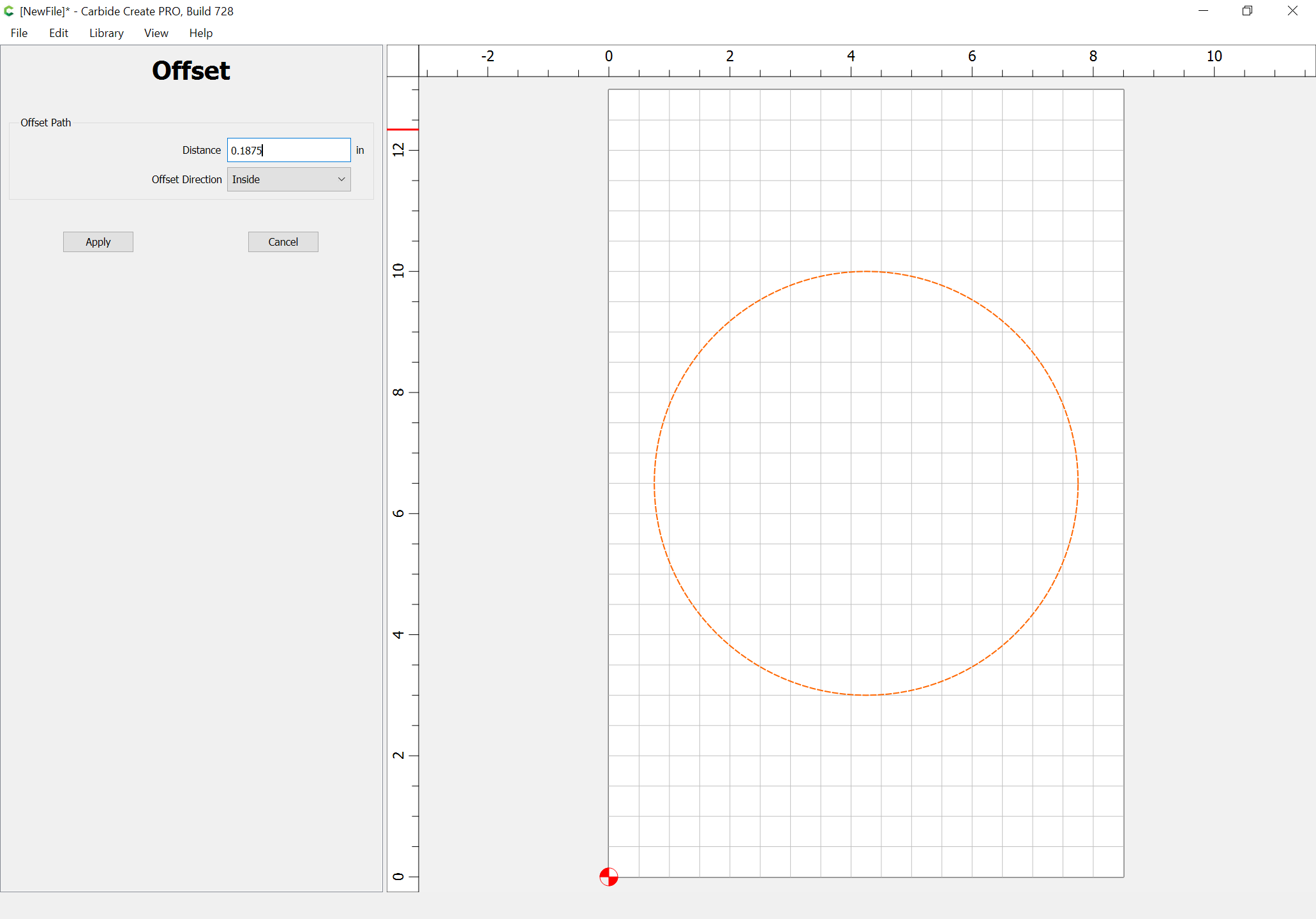
Inset by the desired width of the rim of the bowl:

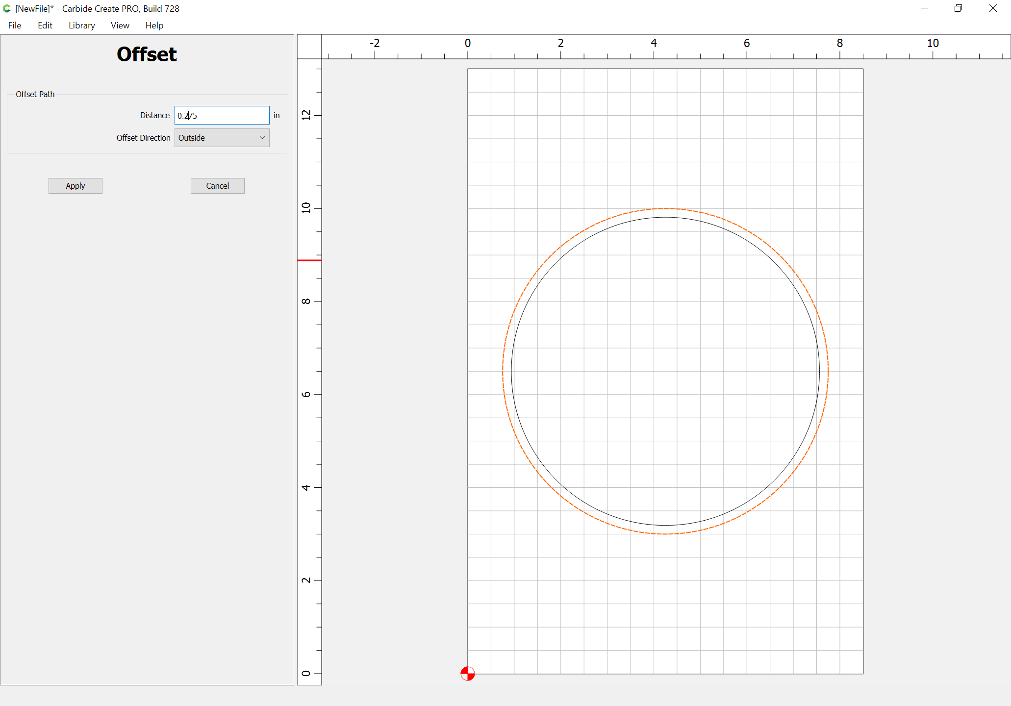
Offset to the outside of the bowl by endmill diameter plus 10%:

Draw in geometry to define the stock (since we’ll be working subtractively):

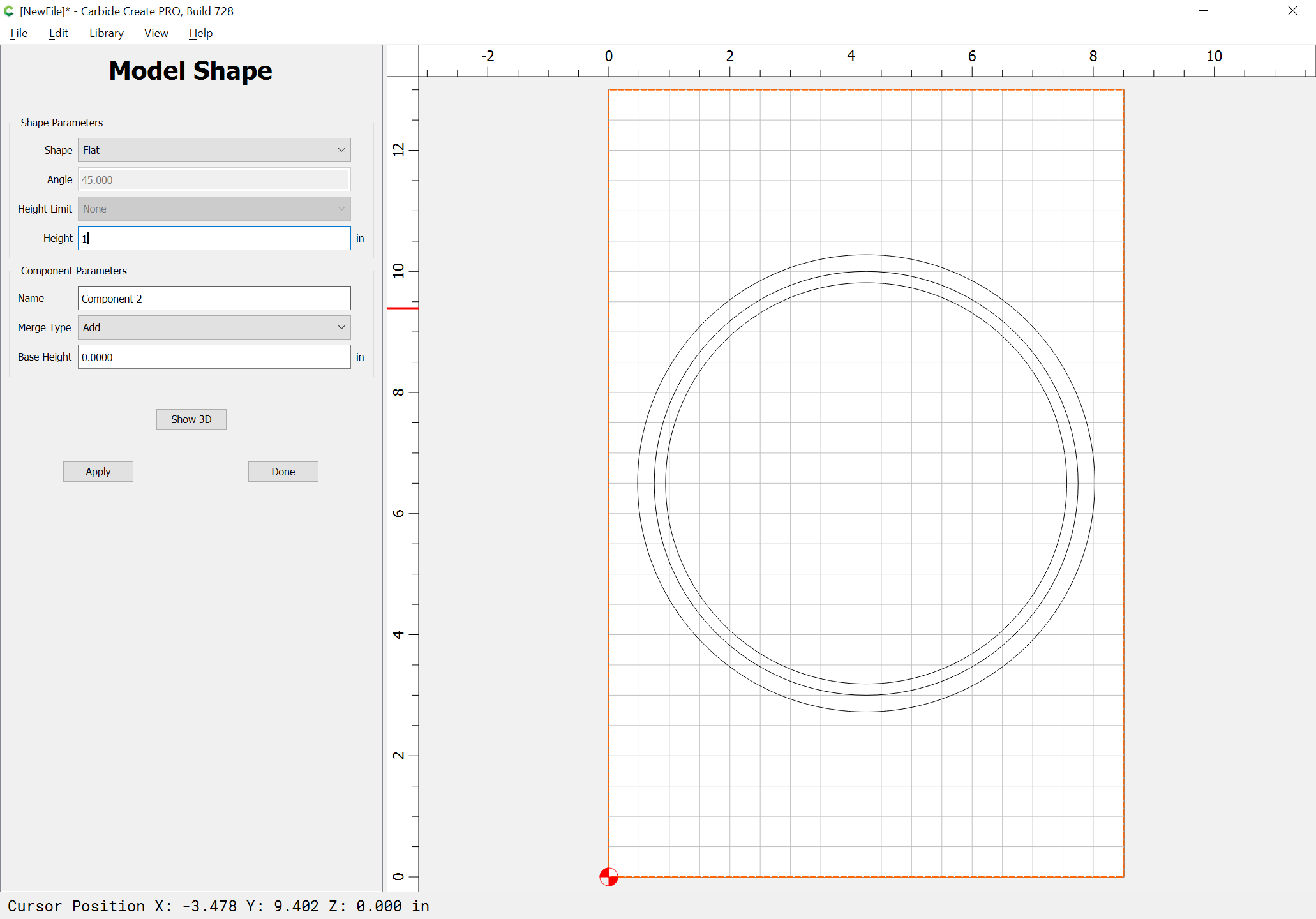
Go to the 3D model tab and model the stock:

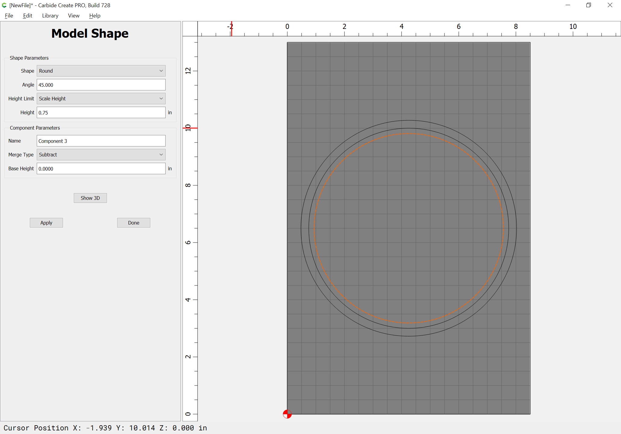
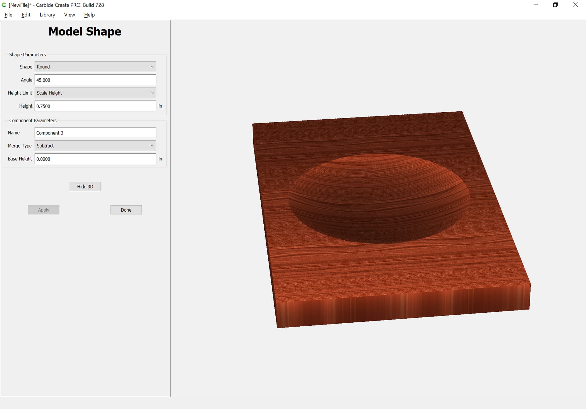
Select the geometry for the inner curve of the bowl and model it:

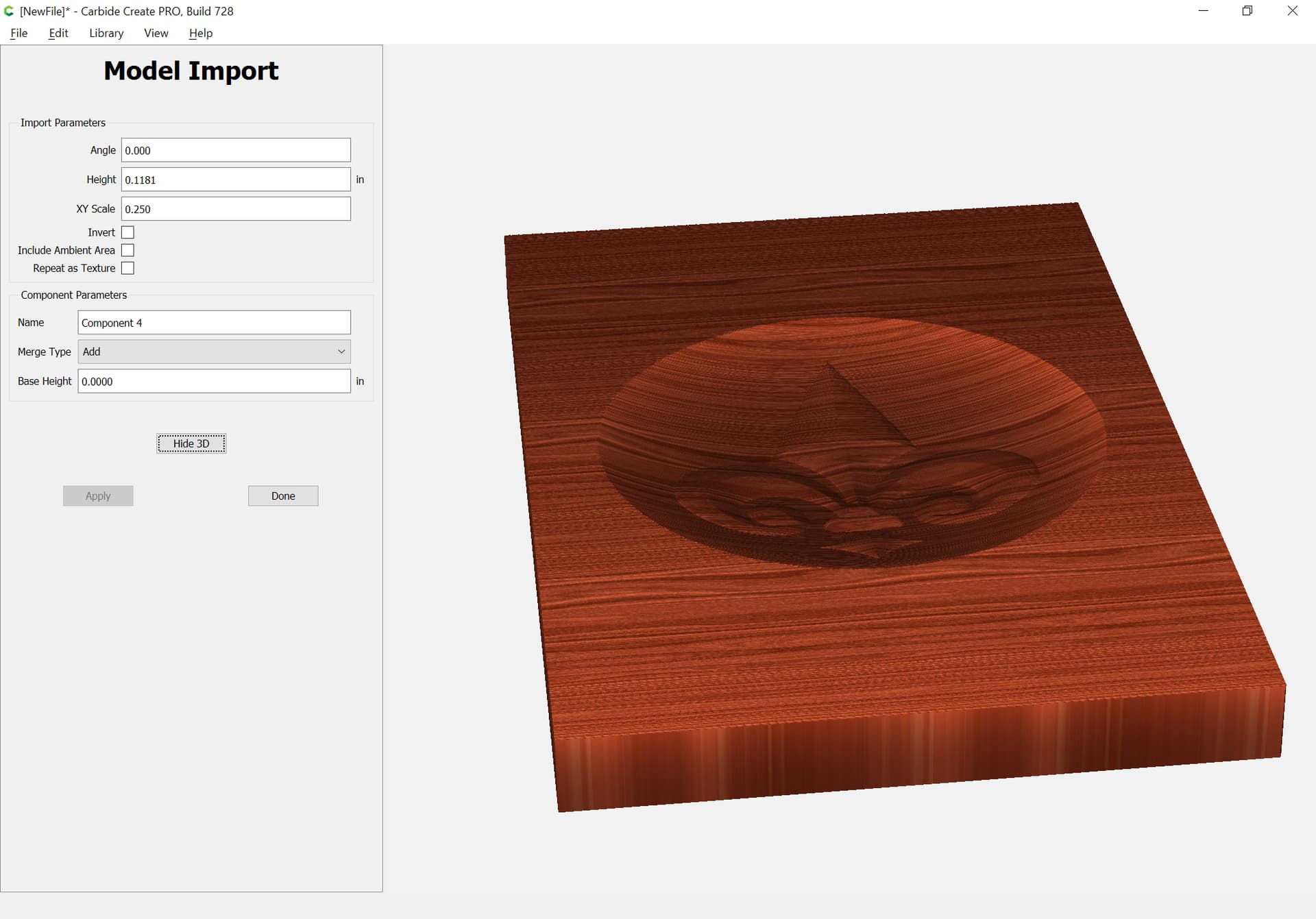
Then import and add the fleur de lis:

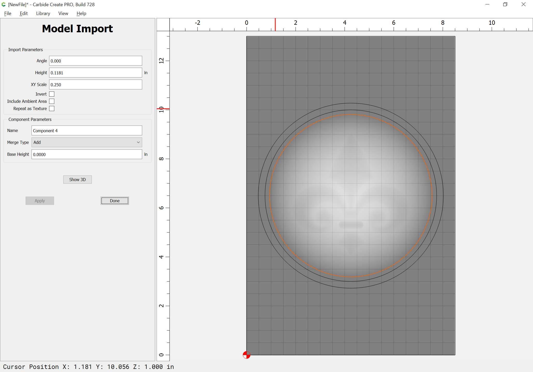
adjusting settings as desired:

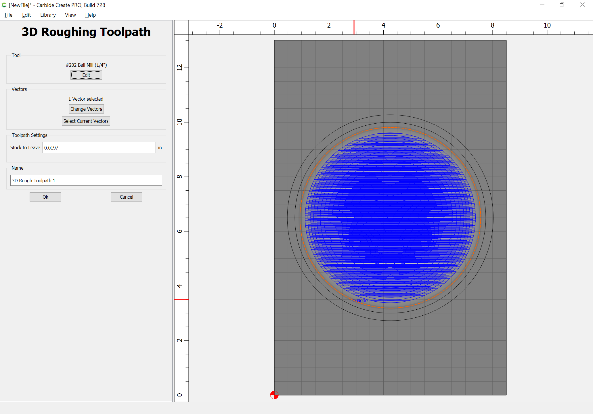
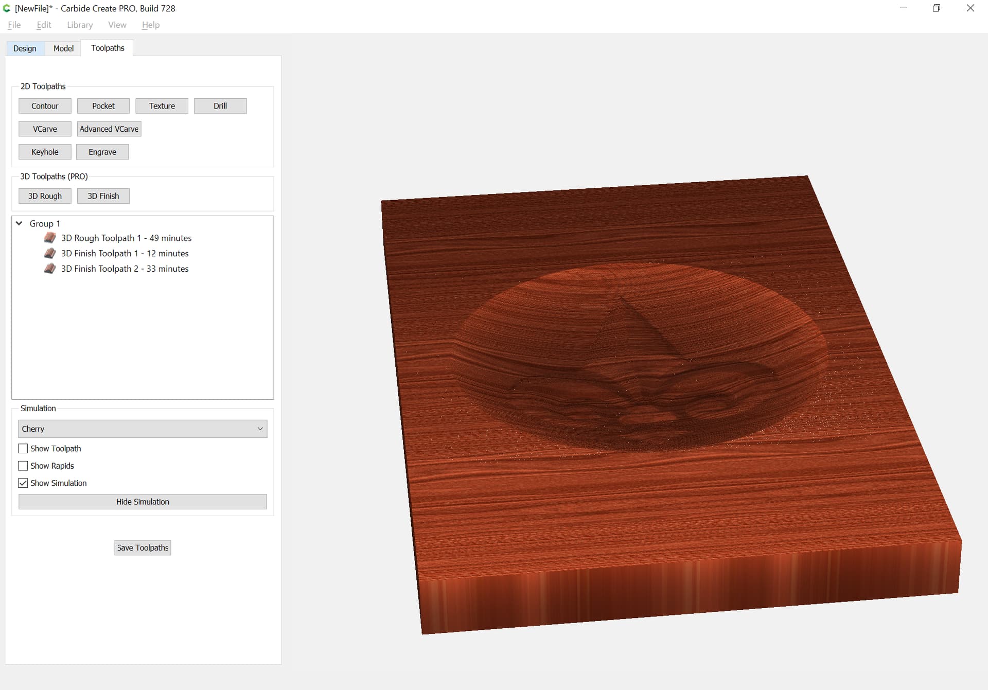
Then model the toolpaths, first roughing:

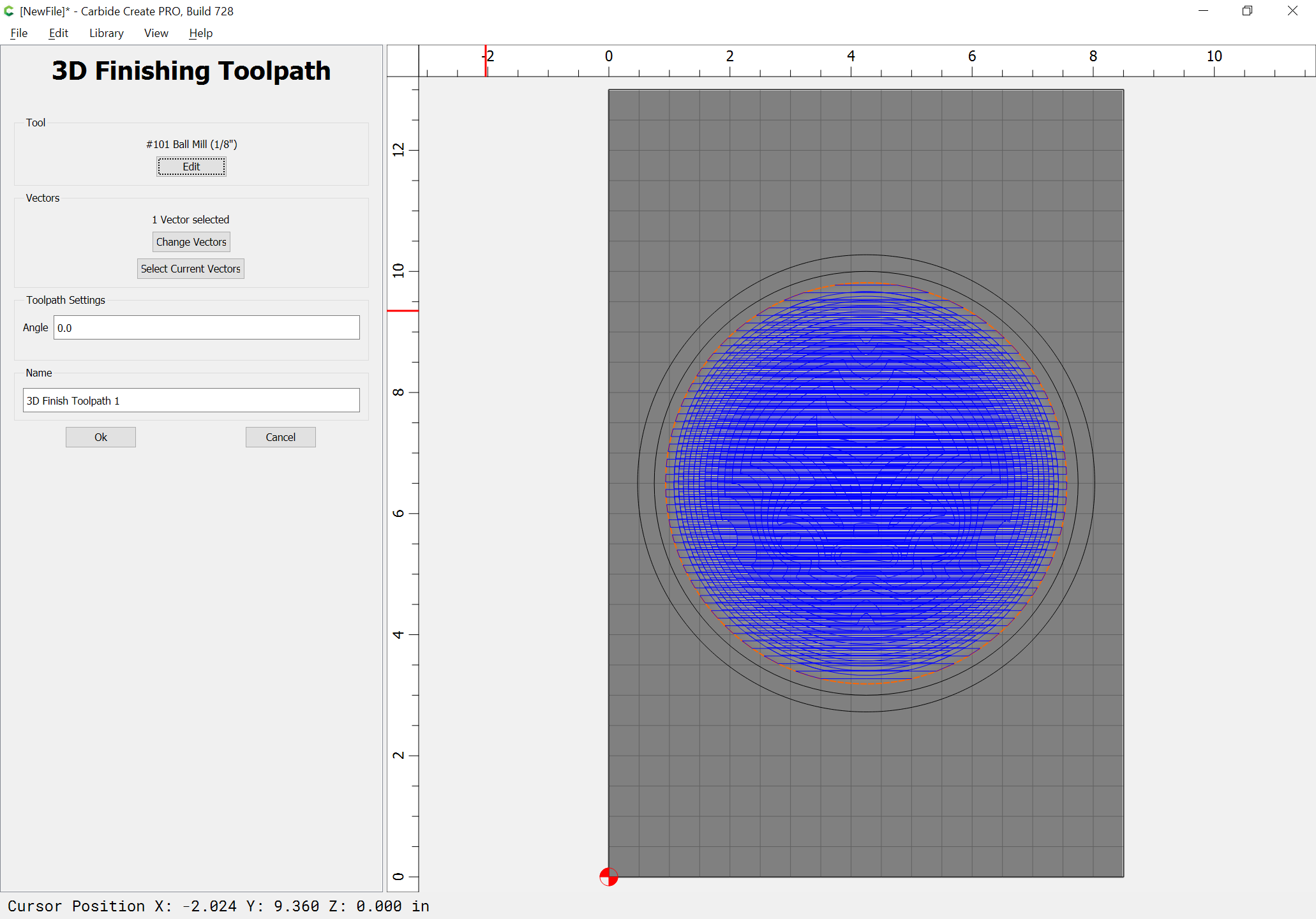
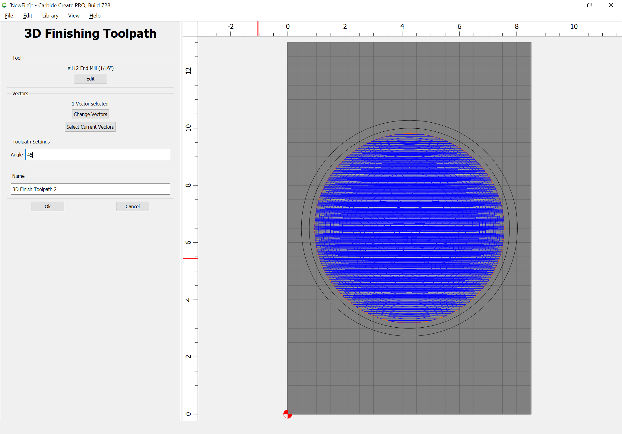
then add 3D finishing toolpaths w/ successively smaller tools until one arrives at the desired level of detail:

Here is a v7 file:

fleur_de_lis_bowl_v7.c2d (1.8 MB)

(duplicate the file and use the non-offset geometry to model the bottom of the bowl)

1 Like

Question for Tod and Will,when you have got to the point in your bowls or whatever,how does the image stay equal from the bottom to the start of the walls.Does Carbide pro just puts it on that surface,if you know what I mean?

If you add or subtract a 3D component, it will be in addition to, or taken away from the previous components — Min, Max, and Multiply will also include the existing 3D model — it’s only Equal which forces a particular height w/o consideration of what has gone before.

This topic was automatically closed after 30 days. New replies are no longer allowed.