WillAdams
May 13, 2024, 3:49pm
1
This is in response to @stra04 's post at:
Before seeing this forum this morning, I emailed the support team asking for help understanding a few features within the Modeling Tab pertaining to importing and working with STL files (I will post the email with pics below). Although I am a fairly accomplished woodworker, I am considered to be an extreme novice in CNC. I have always realized the value of using them for my projects, but I never had the money or the time to purchase one before. Finally, I purchased my first machine, a Shapeoko X…
I wrote up a bit on this at:
The difficulty here is that one needs the underlying 2D geometry, and it needs to usually represent a region in multiple ways — here are the basics of this:
https://willadams.gitbook.io/design-into-3d/2d-drawing
and also see:
This came in from support difficulty in getting a purchased image:
[image]
to cut as desired.
We will review the specifics here.
and:
I see in your recent e-mail to support that you have an STL — that of course greatly simplifies things, see:
https://my.carbide3d.com/gswccpro/07/
and also see
First, configure the stock:
[image]
Draw in the geometry for the bowl and place as desired:
[image]
Inset by the desired width of the rim of the bowl:
[image]
[image]
Offset to the outside of the bowl by endmill diameter plus 10%:
[image]
[image]
Draw in geometry to define the stock (since we’ll be working subtractively):
[image]
Go to the 3D model tab and model the stock:
[image]
Select the geometry for the inner curve of the bowl and model it:
[image]
[image]
Then im…
and
as requested on support…
Given an STL file:
[image]
which one wants to cut out as:
[image]
one first loads it into Carbide Create Pro:
[image]
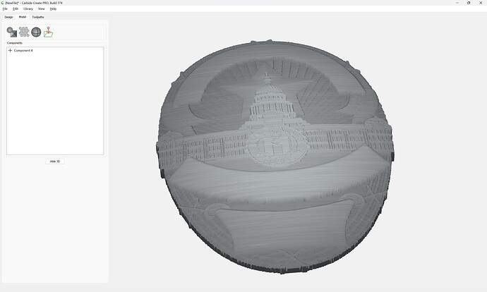
which previews in 3D as expected:
[image]
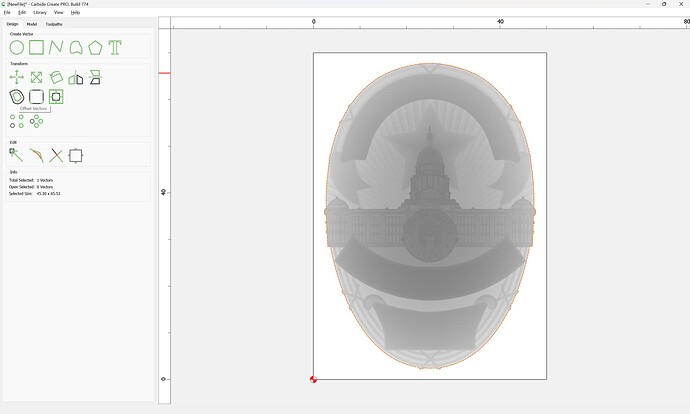
When an STL is imported, the perimeter will be traced:
[image]
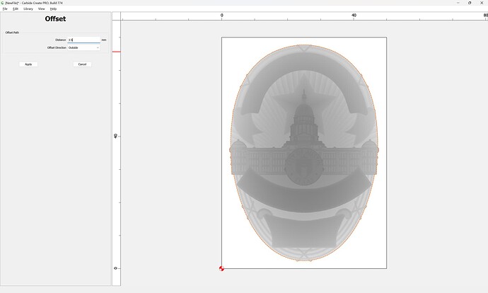
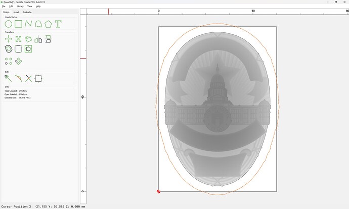
Assuming one wants to cut around the 3D object, one offsets from this by endmill diameter plus 10% or so:
[image]
[image]
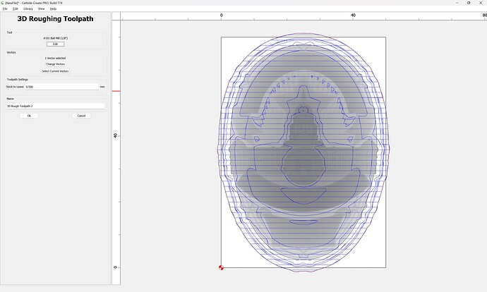
It is then possible to assign a 3D roughing toolpath using this offset geometry:
[image]
[image]
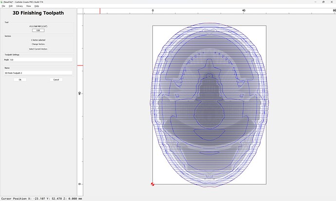
Then a 3…
We should be able to work through this with you on support.
WillAdams
May 13, 2024, 10:29pm
2
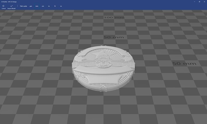
Given the STL file:
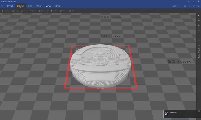
after repairing it:
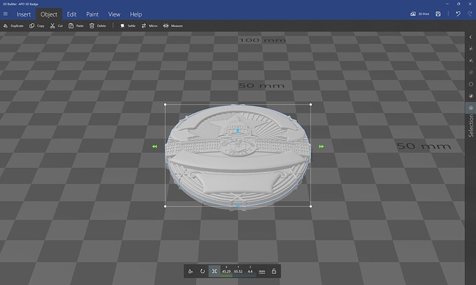
we can then get the dimensions:
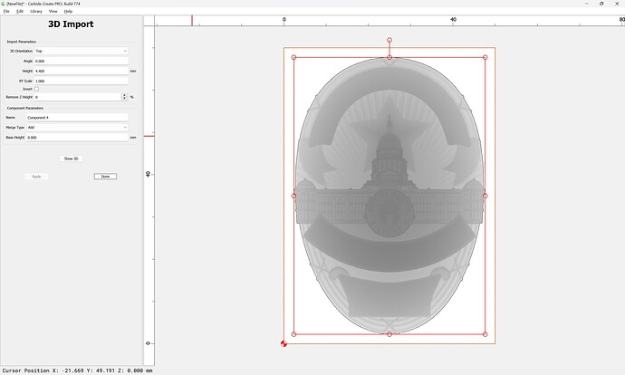
and import it into Carbide Create:
which shows us the 3D model thus made:
To cut the file out select the auto-traced geometry:
and offset to the outside by the endmill diameter plus 10%:
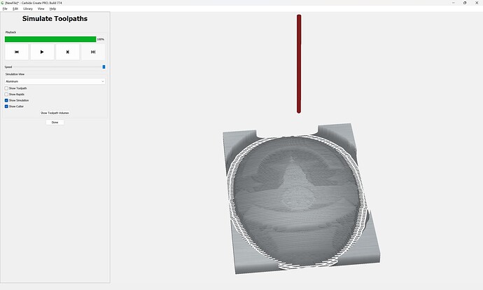
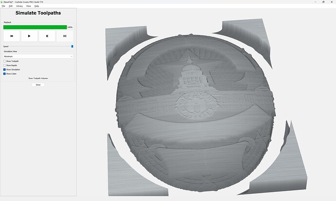
and then apply 3D Roughing and 3D Finishing toolpaths:
Going down to the smallest tool sold by Carbide 3D and increasing the stepover we arrive at:
1 Like
stra04
May 16, 2024, 11:58am
3
Thank you. I think I understand. I have been reading the articles you recommended and am gaining a better grasp of things. The problem is that I mostly only have weekends to reply or study up on the art of CNC. However, from reading through this reply, I do see a few things I did wrong. I will try to adjust and see if I can’t replicate your results working with the file. Thank you so much for the incite.
system
June 15, 2024, 11:58am
4
This topic was automatically closed 30 days after the last reply. New replies are no longer allowed.
