SHapeoko 3 XXL vs Shapeoko 5 Pro accuracy

Start by cleaning things up.

Then check all the mechanical aspects — the basic points of adjustment for a machine are:

  • (for belt drive machines) Pulley set screws — verify that these are in-place and secure — be sure to check all axes/pulleys (including Z on machines w/ belt-drive Z-axis, for an HDZ, check both coupler screws).

  • (for the SO3/4, X- and Y-axes, and the belt-drive Z-axis on Launch and summer 2016 SO3s) V wheels / eccentric nuts (per assembly instructions)

  • (for belt drive machines) Belt tension (see the relevant step in your instruction manual, Note that the X-axis motor is held in place on standoffs and if those bolts are loose this can cause belt tension issues. Also, belt tension for the Y-axis stepper motors needs to be even/equivalent on each side — a significant difference can cause skipping on one side eventually resulting in lost steps on both. Measuring belt tension, squaring and calibration

Naturally, this assumes that all the wiring is in good condition and all connectors secure per the Machine Operating Checklist.

Is the machine powered on and the motor energized? If the machine is off, the motor is not holding and the axis can be moved easily.

If it is powered and the motor energized, make sure the pulley set screws are right to the stepper shaft.

1 Like

Thanks. I am testing powered on: I know that when power is off, I can move the machine around freely.

It turns out that the left side does not move at all, while the right side has the play in the video. And the stepper is turning on the right side, so the link from the belts to the stepper appears to be solid. It is as if the right stepper simply does not care to hold position. Is this a possible failure mode? It functions properly otherwise (I can do CNC runs), so I doubt that the wires are not hooked up properly.

.150" offset is miles off… coming from a 3XL owner.

Since the machine is powered on… It seems as Josh was alluding to. I’m willing to bet the pulley is rotating on the motor shaft. It’s difficult to tell from the video, but the shaft doesn’t seem to be moving, only the pulley. I would ensure the set screw is tight on the shaft flat.

I had an issue not too long ago where my cuts started to drift and noticed as you did, one side of the gantry was rock solid where the other side could be moved when the machine was powered on. The pulley set screw backing out was the issue for me.

OK. I am dumb. Not a stepper problem. Thanks Will and Brian and Josh. One of my set screws was missing, and two were loose. With that fixed, there is no more play in the machine.

2 Likes

Nice! Paranoia and psychosis are par for the course when troubleshooting; sometimes we need simple back-to-the-basics reminders every once in a while.

Curious to hear the report on what kind of results you achieve with the pulley secured - let us know…

I’ve had a lot of Shapeokos over the last 8 years, including a 3XXL…I just have a head start on ya. :slight_smile: We’ve all been there.

Thanks for following up with the issue and fix.

1 Like

I see no reason why not. I have a standard-sized SO3 which uses flip machining without issues. Workholding is key… can you hold the workpiece in the same place every time you place it on the baseboard? You could make the workpiece an exact dimension to butt up to a straight edge/right angle you have placed. Alternatively, a jig that will hold your workpiece and that you fix into place on the baseboard will assist you to machine in the same place. Belt tension is a useful thing to address. I tune my belts with a vibrating guitar tuner attached to the machine endposts until they all read C3 [130.8 Hz.] The Hz value is derived from the informative work by @LiamN (Measuring belt tension, squaring and calibration)

Remember that many end mills will often only be nominally sized. This fact may be responsible for you not getting the accuracy you desire. I attach a couple of images of my baseboard with a workpiece that I can orient in any direction (North, East, West and South on both sides). Consider this the minimum accuracy you must achieve if you are to successfully mill on both sides. Add in belts that may be pulling unevenly, with uneven tension issues, along with end mills that are not the size you thought they were. Add inaccurate and insecure workpiece holding, aided and abetted by baseboard-to-gantry inaccuracies, then you can see that there is a lot to consider before undertaking two-sided milling.

2 Likes

Why does the topic proclaim that it has been Solved?!?

I thought I was going to be writing about how well things have gone, but that is not possible. I still cannot create reliable double-sided (flip) parts.

Our project is complex, with 5 major parts designed in OnShape, 2 of which are large 3D prints (20 hour prints with over 1 lb of filament each) plus 3 wooden (maple) CNC parts. The complex shapes (which need to match each other) are generated as STL files and run through MeshCAM for the CNC. I know of no other way to process STL files into CNC at a reasonable price. We started out using MeshCAM’s flip feature, but gave up on it and are now using two separate job sequences (for top and bottom). Since we CAN get perfect parts, we do not doubt the general approach we are taking.

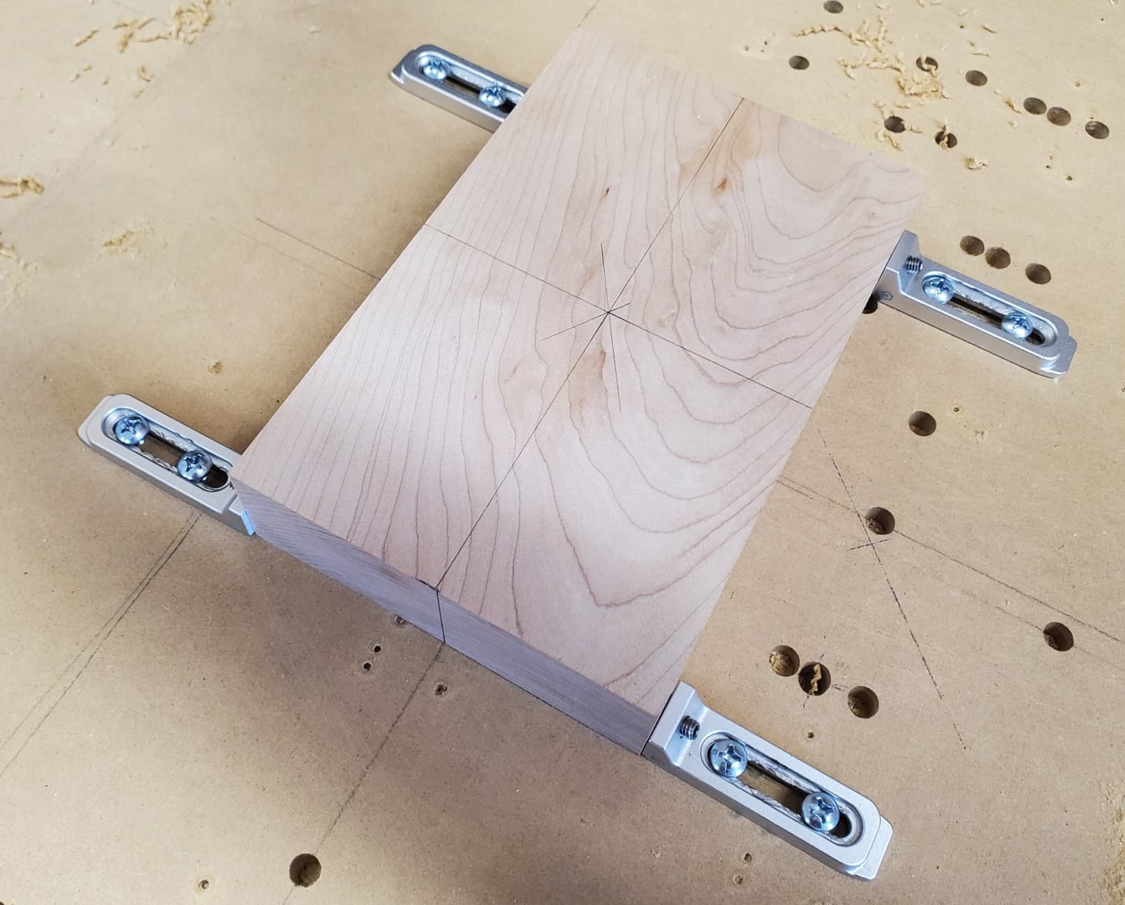
Our general approach for the CNC parts is to create a series of registration holes (for dowels) in the Y direction on the waste board, with a well-defined center (Zero) point. The center of each stock piece is placed at the center of the registration holes, and 4 CNC passes then take place. The stock is held in place using 4 side clamps, and the outside of the stock is never removed. The top roughing and top finishing passes create the top half of the part, along with the top half of two registration holes. The part is then flipped top-to-bottom (around the X axis, not like book pages) and dowels hold it in position, with the side clamps used again. The bottom roughing and bottom finishing passes are then done.

We did this repeatedly using cutoffs from a spruce 2x6 for testing and then tried to make the final parts using maple.

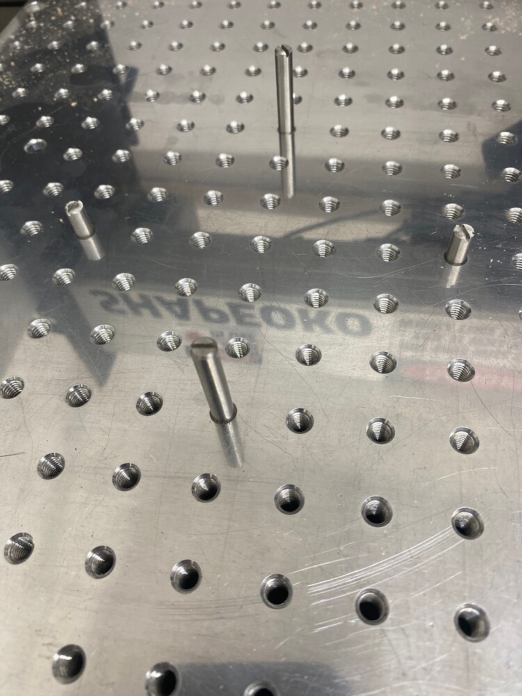
The typical failure mode is that the two top passes do not register with the two bottom passes. There are shifts, usually in Y, but recently in both X and Y. A typical Y shift is 1/8”, as is shown here with a 1/8" drill bit.

We use a 1/4” end mill for both roughing and finishing most of the time, with a 1/8” bull nose for finishing some of the parts. The 1/4” end mill stays in place for the first 3 out of the 4 passes, and sometimes for the 4th pass. The tool is “re-loaded” at the start of each job/pass (really just re-registered).

Some of the problems were due to the drive gears on the Y steppers having loose or missing set screws, but that is fixed. The machine is mechanically solid, at least to me.

I made the mistake of trying to adjust the Zero in the middle of a series of runs, which explains some of the problems for those runs. I now set the Zero in a specific place (and write that down) and ensure that ALL of the passes are made with that Zero (except for adjusting for stock heights).

I now re-initialize the machine just before every run, so at least 4 times for each part.

We made one near-perfect part out of spruce on Monday night, but after that, none of the maple parts were correct.

I have observed some savage changes in Zero after some runs, perhaps as much as 1/4” in X and Y. The Zero is the middle line, so the end mill is off by 1/4".

There have been at least 3 crashes, where the end mill was wrenched from the collet, usually do to user error (wrong Z Zero). The end mills run true, visually, and that one perfect spruce part was made just a few days ago, so the router and end mill are probably OK. The router occasionally stutters, as if it would like some new bearings, but it created a perfect part two days ago.

Possible causes?

  1. MeshCAM could be generating code that challenges the machine too much (it is on the hard wood setting for feeds and speeds). I hear occasional loud cuts where the router RPM falls a bit. Carefully monitoring the process for 8 hours is exhausting, and even if I hear a challenging cut, I have no way to correlate that with the NC files. I suppose I could run over and find what line Carbide Motion is on, roughly, but I have not done that.

  2. The machine could not be strong enough to withstand the cuts, resulting in lost steps. It appears to be fine, but I could be missing something.

We considered running some tests, but with some runs taking almost 2 hours, a 2 minute test is unlikely to be useful to us. If the machine is slowly losing Zero, a 2 minute test will not tell us much.

The major issue is that we cannot produce parts repeatedly. The fact we are able to produce a perfect part suggests the issue has something to do with the Shapeoko itself. The varied results could indicate the machine doesn’t maintain a reliable Zero position.

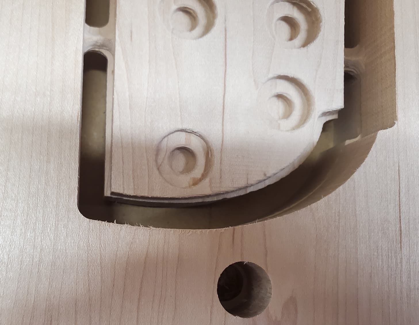
This is the latest failure:

At this point, the entire process is unreliable. There is no way to predict if a part will come out correctly or not. Extremely frustrating, and I am ruining a lot of stock.

Upload a .c2d file and step-by-step notes on how you are securing your stock and setting zero and managing all tool changes and we will look into this with you.

Looking at your endmill…

It has A LOT of what looks to be burning on the shank. Is your flute length at least as deep as your material? If your shank is rubbing the material it may be adding to your issues. It doesn’t seem like it would cause problems, but I have underestimated the effect and had it cause issues for me in the past.

What are your cut settings?
Feedrate, depth of cut, stepover, and RPM.

1 Like

The end mill shank burned during one of the crashes, but continues to work well (remember, I had a perfect part in spruce 48 hours ago). I always ensure that more of the mill is exposed than is needed for maximum depth of cut: that is not the problem. I will provide a spreadsheet with all of the details in a few hours.

MeshCAM says roughing for 0.250 end mill is 3,000 feed rate, 1,501 plunge rate, and 15,000 RPM (rough estimate because I am using the Carbide3D router). Step down is 2.263. Finishing is the same only step down is 0.635. Units are mm.

If you are cutting so deeply that the tool shaft rubs, as @SLCJedi notes, this can be problematic.

Can’t advise beyond that and what has been noted above w/o seeing your file.

In response to William’s request…

The MeshCAM files are SUPPOSED to cut down slowly with 2 mm steps, so the shaft of the end mill should never be pressed against raw wood. And the fact that I had a perfect part 48 hours ago implies that this is not a problem, at least not all of the time.

I have no C2D files, just NC files generated by MeshCAM.

Roughing for 0.250 end mill is 3,000 feed rate, 1,501 plunge rate, and 15,000 RPM (rough estimate because I am using the Carbide3D router). Step down is 2.263. Finishing is the same only step down is 0.635. Units are mm.

Work was held down with 4 corner drywall screws (picture) , but now is held down by side clamps (picture)

Tools are removed and mounted manually with a wrench and then zeroed with a BitSetter. I then re-initialize the machine (in order to eliminate any force I might have put on the system during tool changing) and start the job, at which point the tool is again zeroed with a BitSetter.

X and Y zero are set when I drill the registration holes in the waste board, and never changed. Z zero is set by manually dropping the end mill to the top of the material and using a piece of paper to determine when the paper is just barely trapped by the mill. Given that problems in Z have not been observed, I believe that this process is adequate.

See ZIP for all of the files.

Double Neck Guitar CNC files.zip (3.9 MB)

Have you checked all your motor connectors?

Poor connections with the motor connectors, especially the X & Z axis, are notorious for randomly causing lost steps. This can be especially true when cutting hardwood & the vibrations running through the gantry.

You can easily check the connectors by jogging the axis & fiddling with the connector to flex/bend/strain it a bit. If the movement stutters/stops/grinds then the connector isn’t making a solid connection with the motor.

The connectors should be zip tied securely & some users have found zip tieing the two sides to keep them pushed tightly together so they can’t flex seperately helps.

There is a huge amount to unpack in this post of yours. Without wishing to state the obvious (for which I apologise in advance) any error in your system does not go away because you address a different error. Errors tend to be cumulative. e.g. If your bit is 6.35mm (1/4") nominal and it has been manufactured cheaply so the size is too big by say… 0.1016mm (0.004") you can expect the displacement from your expected location to be 0.004" out.

One could be forgiven for thinking that moving the workpiece in a corrective direction would fix the issue… it cannot because the ‘solution’ does not take into account runout of the spindle or wrongly tightening the collet when it has debris in the collet taper. Other effects may be caused by poor workholding, poor technique (I noticed the overheated 1/4" cutter) or simple mistakes.

In your position, I would not be inclined to machine any stock with so many different issues to be resolved. They are all possibly related to different causes. I am arguing for you to stop the job completely, fix any issues with the assembly of the machine and then practice on scrap until the machine is obeying your instructions and you are getting the correct result. Even a badly set-up machine should manage to move stepper motors to within a reasonable distance of the expected location. say… 0.005" which ought to be good enough for many woodworking projects.

The computing side of the process is unlikely to be sending the cutting head to locations 1/8" or 1/4" distant from your intended cut point. These are huge distances, especially when I have found that the normal range of accuracy obtainable from well-tuned Gates GT2 9mm wide belts is easily ±0.001". On one occasion, with very careful tuning and an expensive cutter, I was able to work to ±0.0004" on an aluminium billet.

Summary:
Take your machine apart ~ every nut and bolt and re-assemble it to the highest stand of accuracy you can manage. The rails must all be square to each other and square to the baseboard. The stepper motors must be mounted so there is no play. The X rail and Y rails should not have any endfloat when tightened…that is to say that there should be no end-to-end longitudinal movement. Your X rail carries the router and it should be square to the baseboard without leaning forward or back on the router carriage.

The carriage should not lean from the vertical in either left or right direction. The router must be firmly fixed to the carriage and you should be aware that the collets are easily damaged and are a consumable item. The collet taper should be cleaned of debris every time you change the bit. Use a vacuum hose or an airline to clean the collet taper.

Always tighten the collet the same way and to the same tightness. Bits being pulled out of the collet during machining often reflect a lack of tightness. It can also be too high a feed speed and too big a cut as well as slotting rather than adding geometry so that you do not have 100% cutter engagement. If the cutter is engaged with the workpiece over 100% of its cutting face, you generate excessive heat and lose the accuracy of your bit and damage the workpiece.

The large displacement errors you discuss strongly suggests that your machine is not accurately assembled. I would start there before looking at anything else because if your machine is not square, nothing you do afterwards will be square, notwithstanding any of the potential errors I have indicated.

Jeff:

Yes, there is huge amount there. I’ve spent weeks on this.

Briefly…

I practiced on scrap, and got a perfect piece out, so that certainly is possible, even without disassembling the machine. Believe me, 0.005" would be fine with me.

I have no intention of disassembling the machine. It made a perfect piece once. Something else is going on. The comment about loose connectors makes sense to me: I intend to look into this.

Cleaning the collets is a great idea.

The bits were only pulled out after there was a HUGE error in the job, with the wood horribly mangled. The collet was tight: the job was the issue.

I cannot speak to how well MeshCAM is moving the end mill, other than to say, for the 10th time, that I got a perfect part out 2 days ago. This speaks against your argument that the machine is not assembled properly.

What results did you get with the diamond ~ circle ~ square calibration method? Ten attempts should provide clues as to the degree of misalignment, the timing of the off-kilter happenstance, and the type of cut that caused it. Most importantly, you should also get some information about the factors that pertained before the error. Keeping accurate logs is tedious beyond belief, but very worthwhile when troubleshooting problems that seem to defy analysis

The one perfect piece meant all of the required factors were present and confluent, so you got the result you had wanted. Did you record your methods?

It is essential, if you want to have the collet sitting tightly against the collet taper.

OK. I believe that eliminating every cause of malfunction has to begin at the beginning. I know and understand that starting again from machine assembly is a huge pain in the posterior. I did it myself when I was not getting the results I desired. The difference between my assembly when I first purchased the machine and the rebuild some months later was night and day. I guess I just did not know enough to build the machine competently. After the rebuild, I started achieving consistency and that demonstrated that my original build, while looking good, was faulty in several important respects.

Because of the myriad reasons that my work was not what I had expected nor desired, I opted to remove doubt about the faults in building my machine and then set about analysing the techniques after ensuring that the build quality was not responsible for my many faulty carves.

In so far as I am aware, NOTHING was different between the successful job(s) and the unsuccessful job(s).