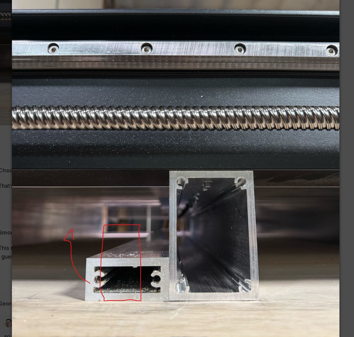
Based on the photos of the new extrusions it seems possible to remove the spoil boards and then swap out each extrusion one for one and maintain square. My machine is spot on and this would save some time to not have to repleat the entire process. Square checks will be performed during the swap, just to make sure.
Besides… this allows me use that really expensive heavy duty “red” square and lower its cost per use ratio!
I think you could swap them one at a time, and that might be how I’d go about it. But it’s probably a two-man job to lift the machine to get the new tubes in place. (Or, one engineer, who’s waaay overthinking everything and taking twice as much time)
I am seeing the potential here for a future added 4th axis rotary to the Shapeoko 5 Pro with all of these base upgrades. By opening up the space between the table and the machine, a rotary could be added as an inset to the machine surface. This way part of the material would be under the surface of the machine, so that, not all of the material in the rotary would be restricted by being on the top of the machine table. The height of the table surface and the gantry clearance is only 4.25 inches. If we are seeing an increase in table height of 4 inches, there will be potentially a total clearance of 8.25 inches from the surface below the table and the clearance of the gantry.
A cutout on the table allowing for the rotary insert would be great because then we step into the realm of complete 3D carving, not limited to flat surface 3D carving.
I hope this is the direction the devs are going with these upgrade ideas. I think the only limitation that would be there is the programming necessary for designing 4th axis 3D designs and getting away from programming issues. The computing requirements would be higher, but maybe worth it for many of us that would enjoy being able to run 4th axis, also known as A axis, designs.
If this wasn’t your intentions, then it surely is something to think about for future developments of the Shapeoko machines.
Just need to fab some quick spacers to go in between the existing extrusions and Y rails to fully support them and then swap one for one. You know, like rotating the tires on a vehicle.
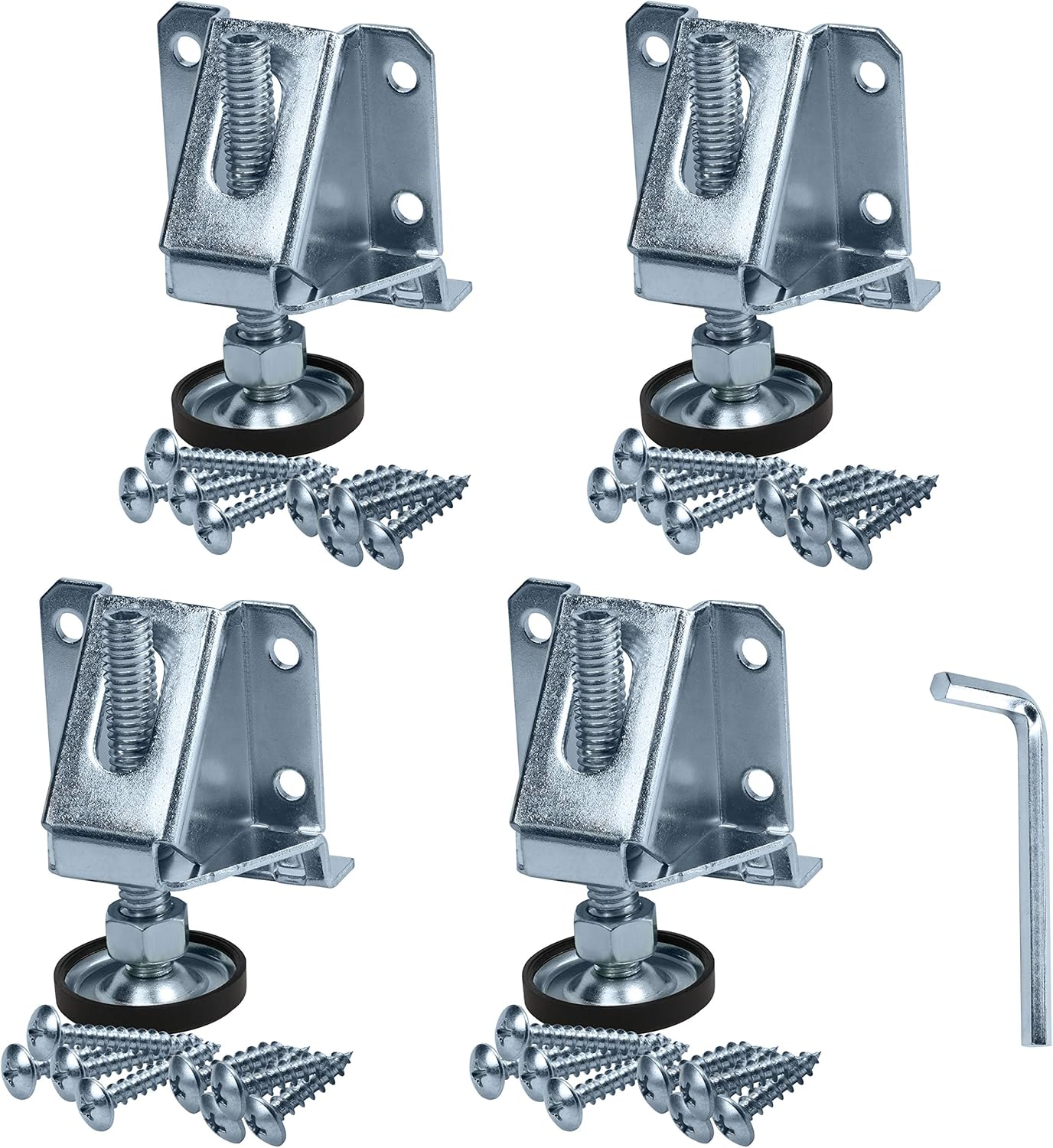
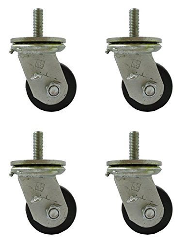
The feet are mounted through M12 holes in the legs, so you should be able to use any wheels with an M12 stud on them. But, be sure to use wheels that lock very securely to make sure you don’t get any wobble as the machine moves.
I echo @robgrz . Make sure you get good double locking casters or the machine will try to walk across your garage. I like Rockler’s Total locking casters. But they have a 1/2" stem, so you would have to drill out the holes if you want to use that solution. Otherwise there are less expensive options on Amazon, I may try when I get my S5 to S5.1 conversion kit and legs.
I haven’t tried Bennington Caster wheels yet, but will for an upcoming workbench build. Neat design and seemingly made by mom-n-pop operation in Pennsylvania.
Thank you for the sizing on the casters. I purchased the legs and am going to try them. I’m a little nervous as I am used to a cabinet under my CNC. Having said that I see holes in the legs that may allow cross bracing. I was hoping to at least get a platform underneath and possibly boxes for drawers in the front. Perhaps even a power box in the back for all the sensative items. I then need to find a comfy spot for a laptop and a surface to place tools, clamps, etc.
I’m going to dump all my 5.1 questions on you guys.
Does the above plan seem feasible? Braces, platform, drawer boxes, etc.
Do you recommend cross bracing prior to casters? Do you have a hole size on the legs for those holes that are mid-way up on the legs?
Is there a printable supplement to the 5 Pro installation instructions?
How difficult would it be to transition the 5.1 to a table from the legs?
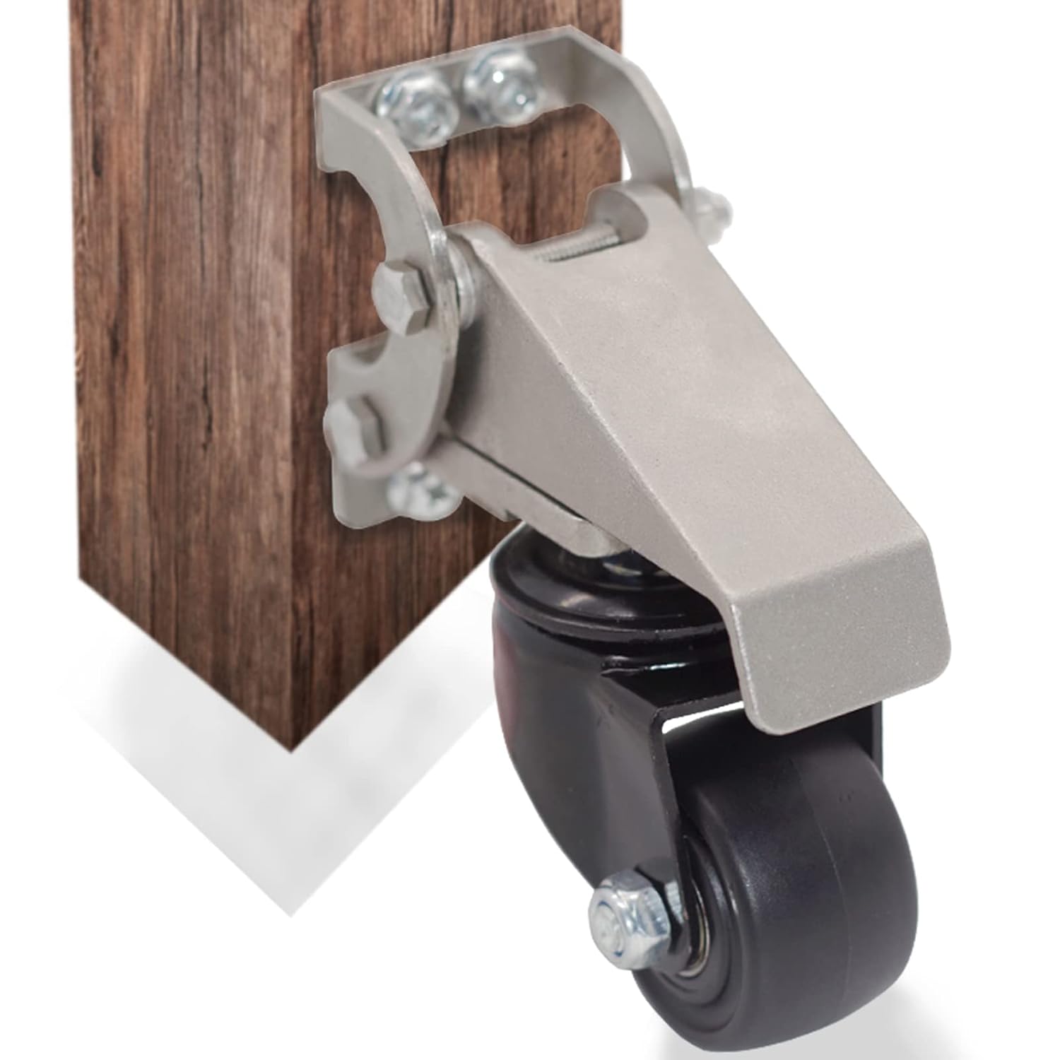
The last picture of the wheels are toe busters and ankle biters. They stick out and have a tendency to catch your feet. A better version are ones that have brackets that the wheels attach to. You buy brackets for everything you want to move and one set of wheels. When not deployed the table/bench sits on its own legs and it only takes a minute to attach the wheels. Then after moving you take them off.
The double locking casters work well but over time the overcover on the wheels deteriorates and peel off. Then the wheels wont lock anymore. I have taken to buying steel wheels for things that dont need to lock. The steel wheels never give me problems.
Hmmm…looking at your pitch. If you rotated the bottom cross member (called a Nomad tube, I think) to the orientation you marked in red, wouldn’t there be less overall surface area in contact between the Nomad tubes and the Y-Axis tubes? And wouldn’t that mean less overall stiffness?
While you could do that (and if you’re out of warranty you can do whatever you want), it wasn’t a realistic solution for us. You wouldn’t get the surface area or stability needed to do vertical workholding, and there’s just not enough meat in there to properly outfit a machine like that with legs, if desired. This is a case of bigger = better.
I agree with Winston if you have the $$$ to spend, I say go for the kit. If not, I was just saying to use the tubes you have you could do this…
To increase a box beams stiffness you need to increase the beam’s depth, this is based on the tension and compression loads do not change. This is the most impactful change, as stiffness in the bending direction is proportional to the cube of its depth. Making a beam twice as deep increases its stiffness by a factor of eight. Which in this case with these tubes rotated 90° it would be significantly stiffer.
The decision is yours to make. I assume no responsibility for the change.
I like the thought to reuse what is available. When I upgrade to 5.1, I may use the old base tubes to run to what look like holes halfway down the legs. Or maybe I can reuse them to aid in vertical workholding.

 I like Rockler’s Total locking casters. But they have a 1/2" stem, so you would have to drill out the holes if you want to use that solution. Otherwise there are less expensive options on Amazon, I may try when I get my S5 to S5.1 conversion kit and legs.