A while back there was a thread discussing belt tension, I had been working on a model for a few months now, was waiting on some hardware. The initial designs are completed although it needs some tweaking, it seems to work well.
The current system relies on crimping the belt down, and using lever action while tightening, to apply tension. I had problems adjusting it after initially tightening, due to the fact that the method basically destroys the belt by bending it sharply and crushing the teeth and makes it very difficult to adjust afterwards.
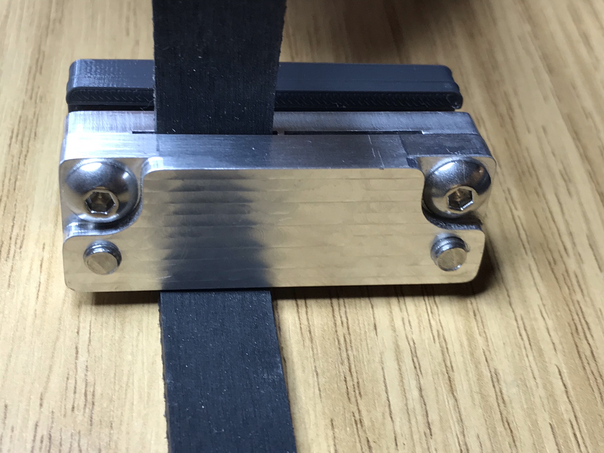
My design is meant to gently tighten and clamp the belt without damaging it and allowing for future adjustments.
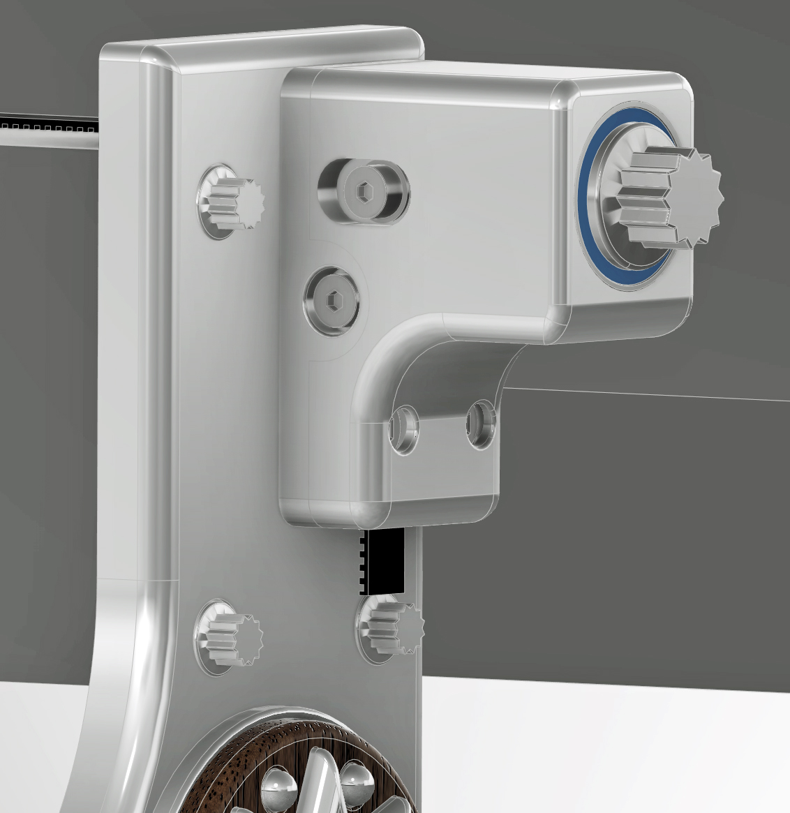
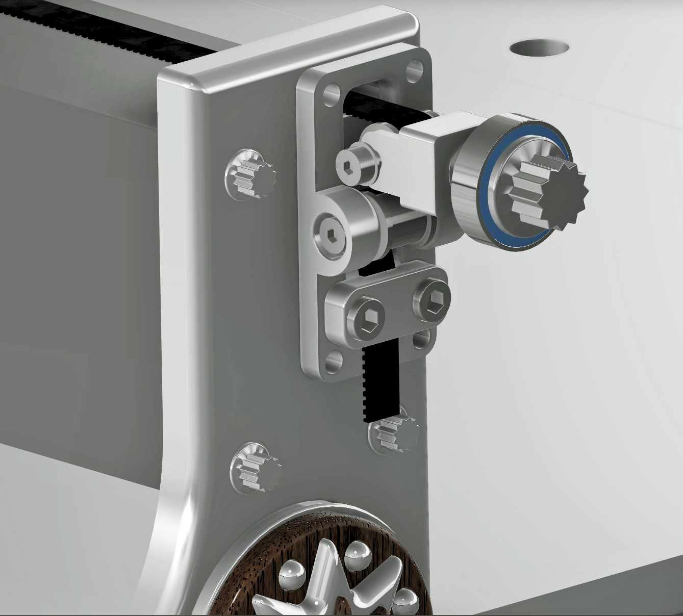
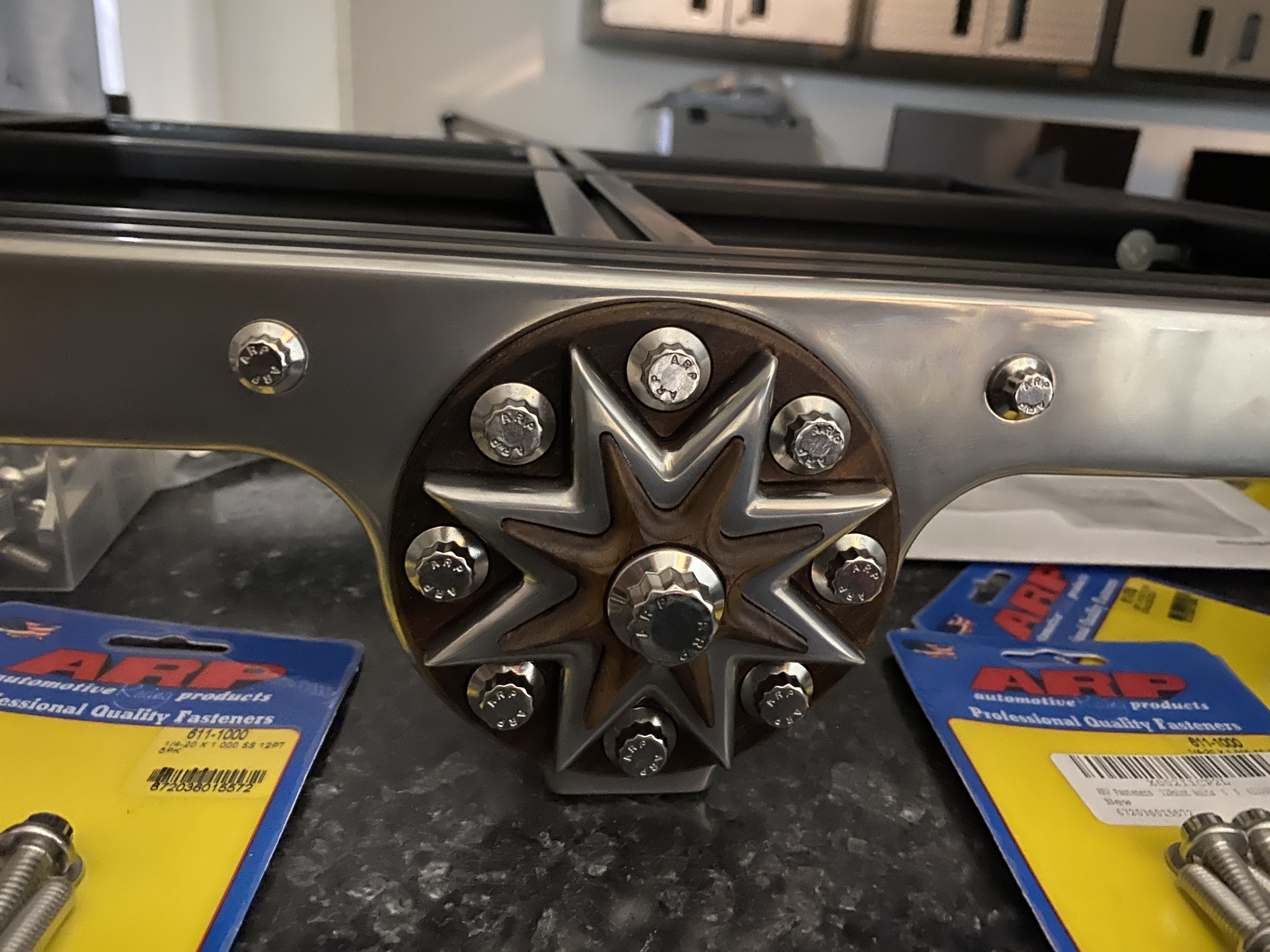
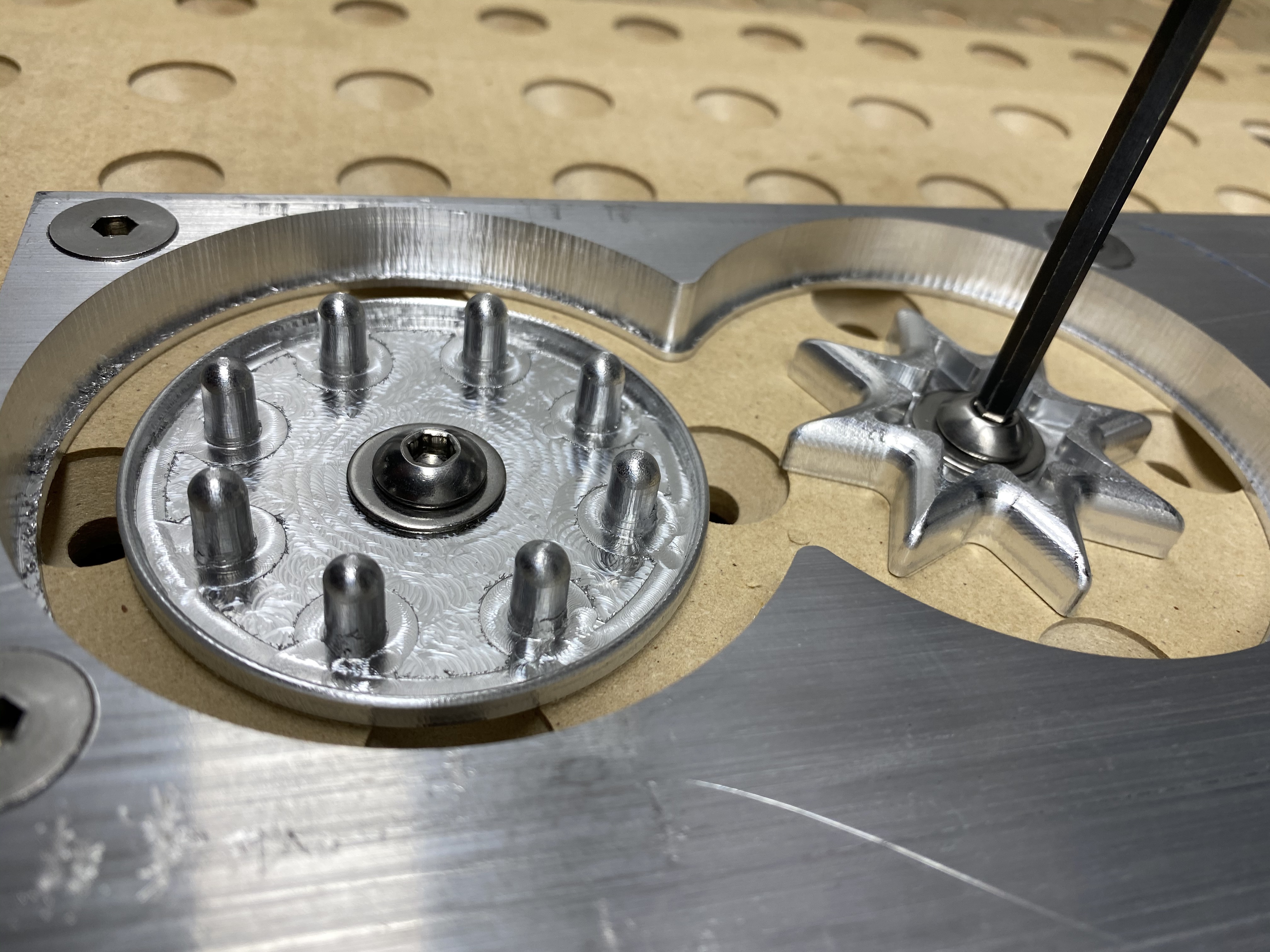
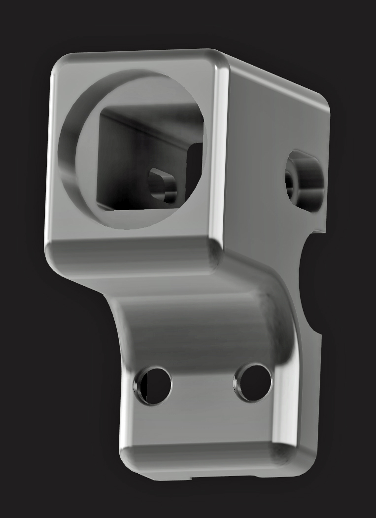
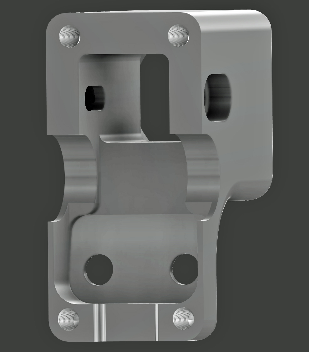
Once the belt is fed into the mechanism, it is clamped down on a GT2 clamping block designed to interlock with the belt teeth, This will not damage the belt while allowing it to be locked down. The 1/2" fine thread ARP bolt rides on a 1/2 bearing for smooth operation, and allows for almost a half inch of adjustment which is far more then needed. The belt can easily be adjusted using the two access windows over the top of the Allen head bolts holding the belt clamp and pulling on the pig tail on the bottom.
I will make a bracket to mount it to the stock S3 frame as soon as I am finished with my 80/20 frame builds. It will require frame removal and minor drilling and filing for a belt access window.
I have ordered some springs and plan on making a tension gauge next to be able to fine tune the belts to be the same tension.
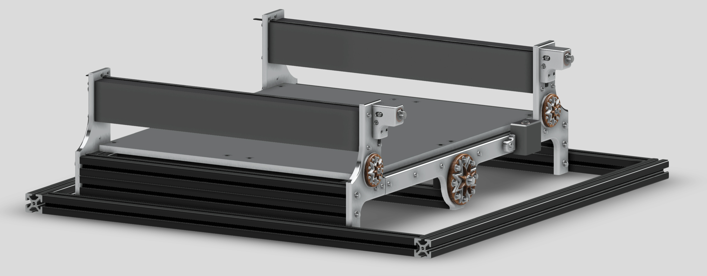
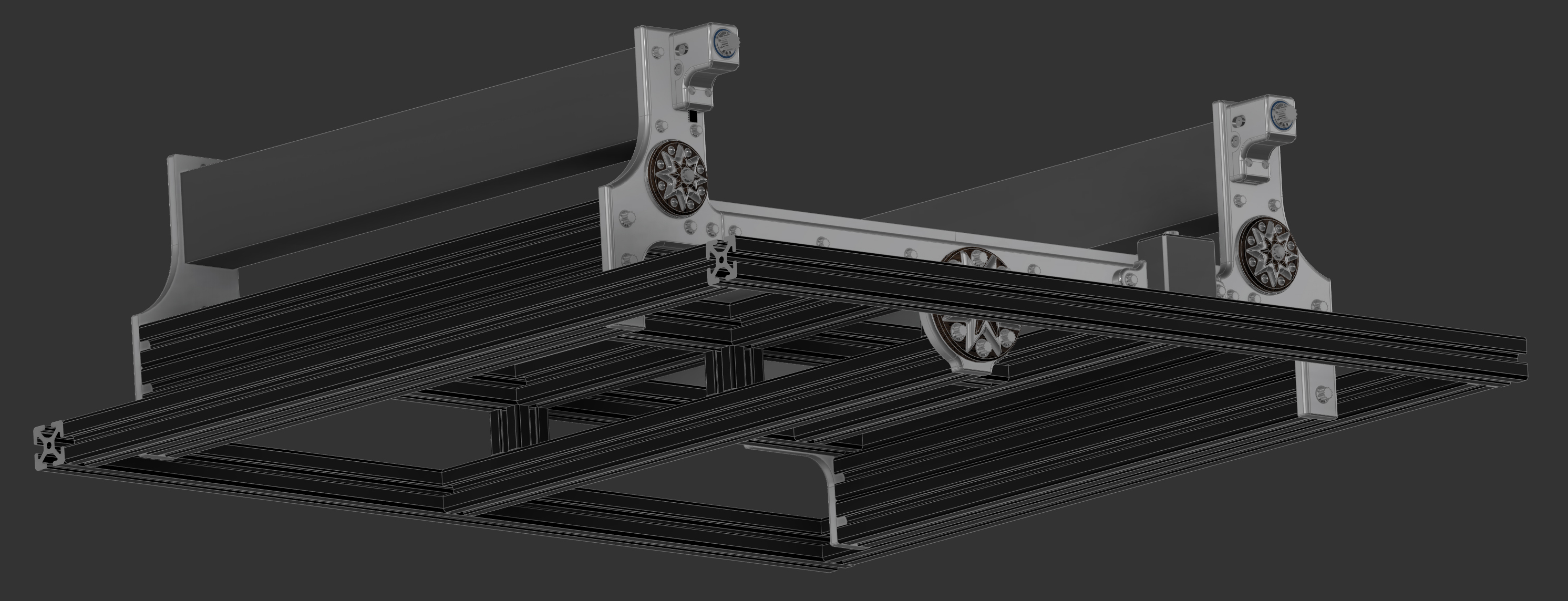
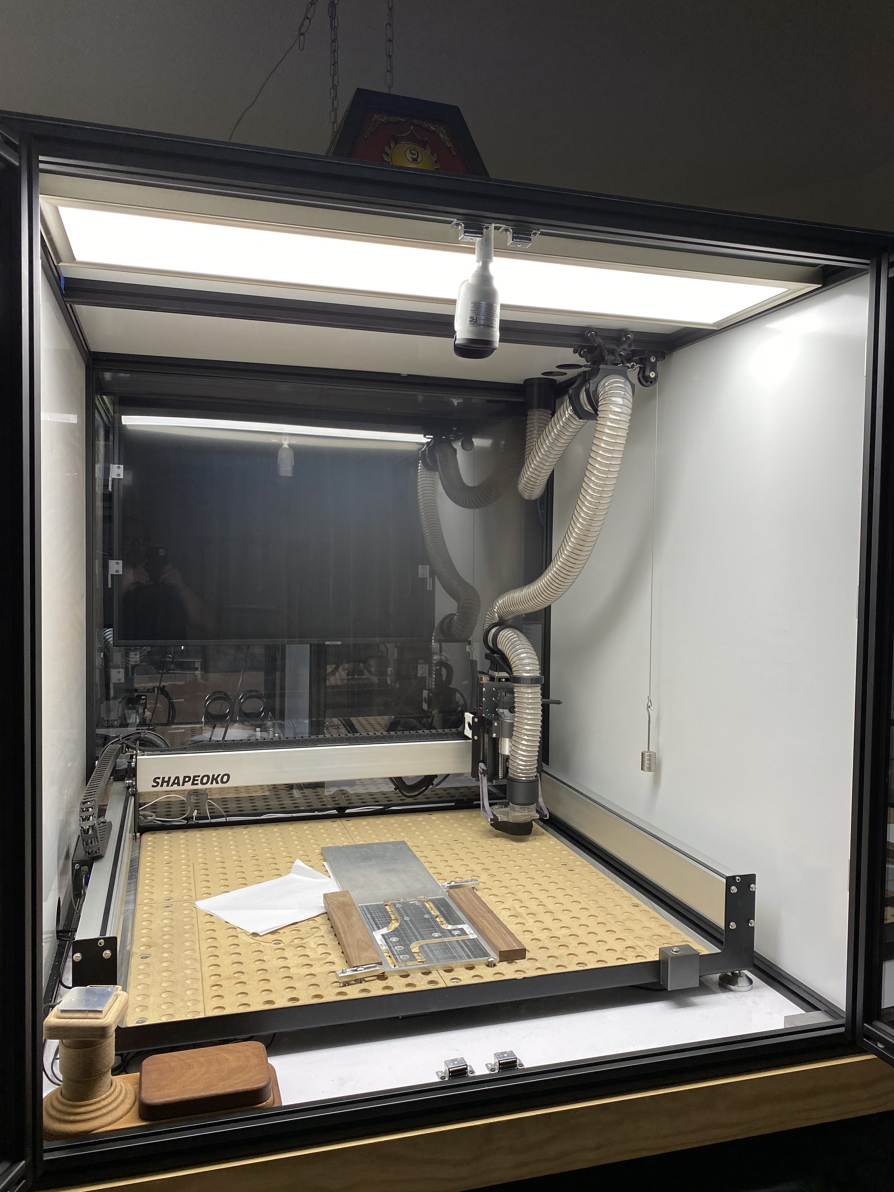
I included some of my latest renders and photos from my current S3 80/20 frame build.
Fusion Viewer


Pretty cool design !
I’m slightly confused by the “pushing on the bearing” part though, would it work by just pushing against a washer embedded in the 3D-printed case ?
Do you tighten the “side” screws of the pulley after you have tensioned the belt using the main bolt?
The shoulder bolts when tightened slightly compress the inner workings which in turn locks everything down. I had considered a set screw, and will implement after testing if needed.
It could definitely be made to function without the bearing. It costs about 2 dollars and
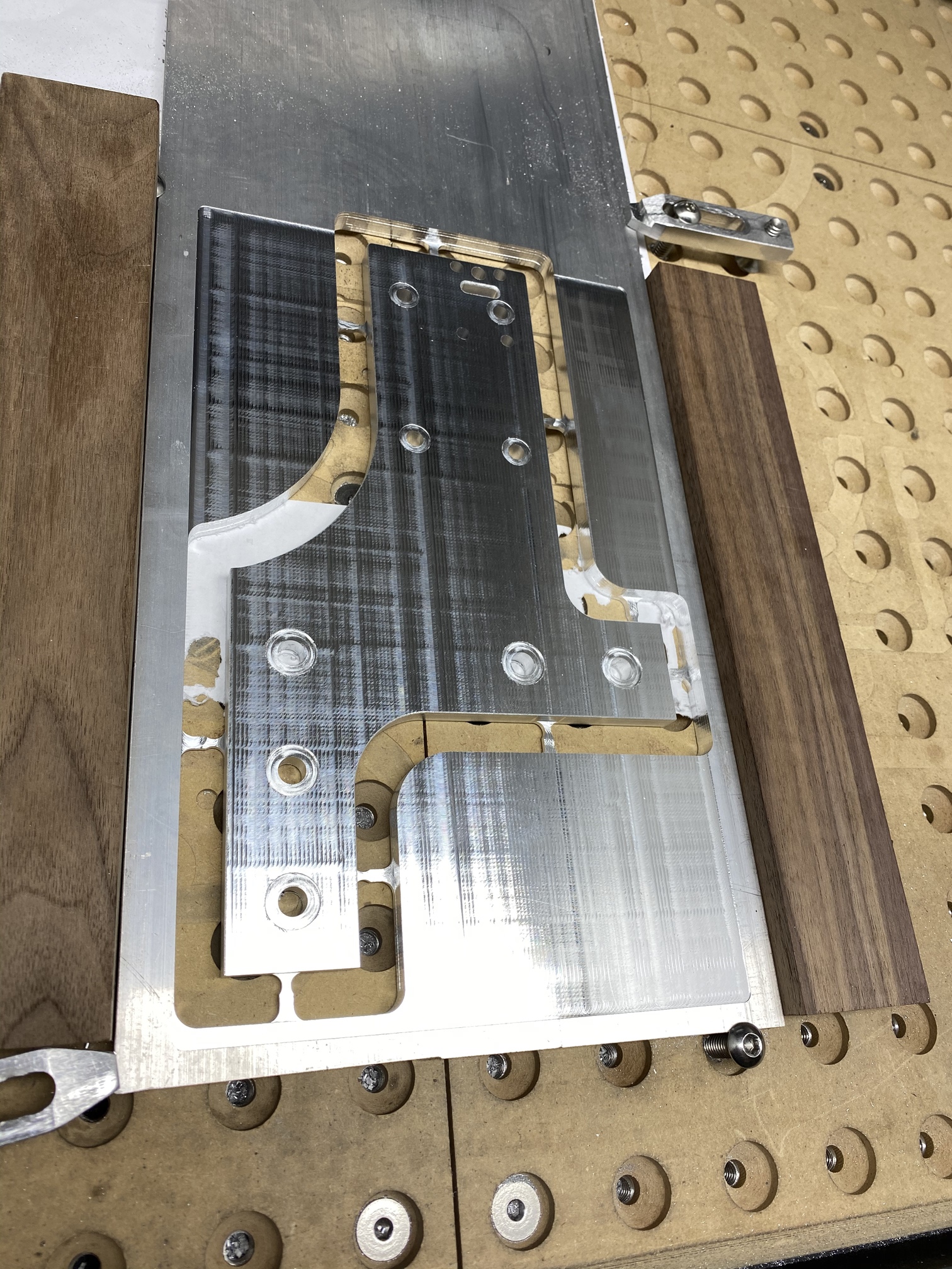
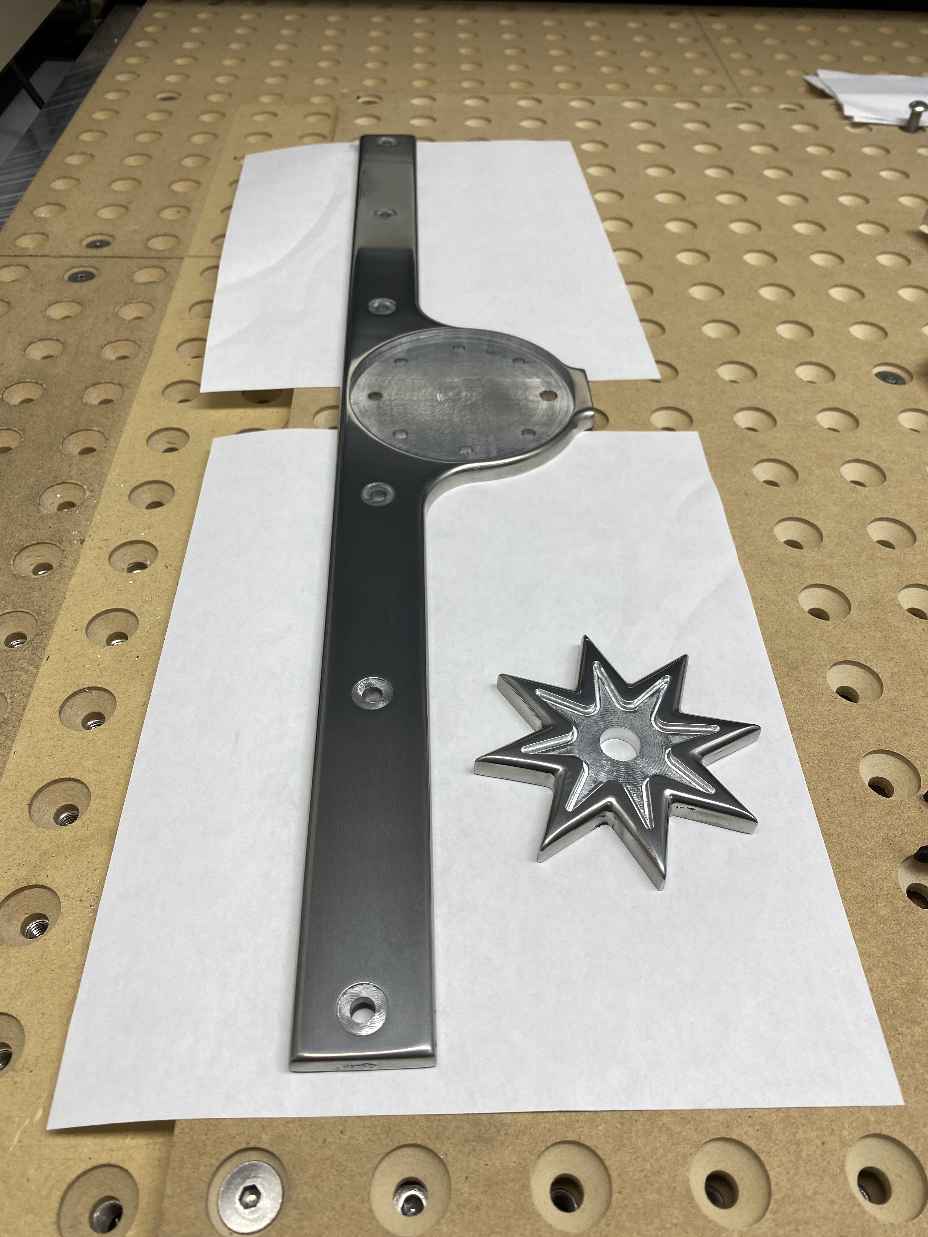
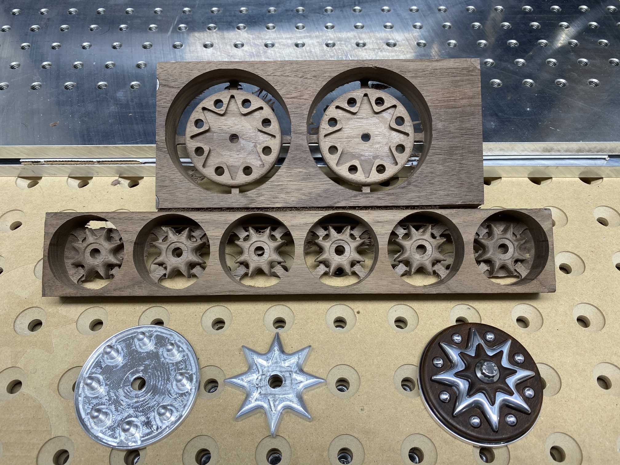
I plan to explore making 3d printed jigs and perform a 5 sided operation and try to carve this out of aluminum and polish it.
The ARP bolt nestles inside the 1/2 bearing perfectly and can be repeatedly adjusted very smoothly due to the fine thread on the ARP bolt, it can have fine adjustment without causing any wear or scratches.
Beautiful design as usual Max 
Why am I always the “wet blanket”?  Isn’t this solution just a tad bit over engineered?
It looks great, and I certainly see that it would work well, but does a belt tensioner really need a ball bearing and mighty fine threaded adjustments? I think some folks are tightening the belts with their ears now.
The reason we all bought a Shapeoko was that simplicity reduced the costs involved.
You have a great engineering talent, so why not design a tensioner that is really simple?
It is, but sometimes that’s part of the point, like the way the Victorians built their steam engines and water pumping facilities, a celebration of the technology.
You could engrave a scale on the face by the bolt to describe the mm (or thou) of belt extension being applied per revolution of the bolt head, that’s all knowable from the thread pitch and geometry.
Edit - that said, my custom belt tensioner is simple and not very pretty…
Prove it… ![]()
nice work @CNCInspiration
I would like to know how you “polish” your aluminum parts?
I’m always impressed by your work, it’s very inspiring.
and have a class on aluminuim work 
I’m just starting, I had to make two pieces in aluminuim, if you have any advice, I’d love it.
and where to buy aluminum blocks at a reasonable price?
Thank you for the very nice compliment Tex, but that was my simple design! Oh by the way it has 3 bearings on each side, lol. My thought process was not saving money, (Total for this build so far is about 30 dollars in hardware.) it was creating the best design I could! I looked at the designs of Creality 3d printers and similar methods of belt tightening, the only examples I could find for inspiration.
Constraints were mounting vertically and converting the belt path from horizontal to vertical, using the only 9 mm belt pulleys and 30 mm shoulder bolts I could find. Also needed a design that would work being 3d printed and wanted it to look good.
I love ARP bolts, I don’t know if you are familiar with race car parts but it matches my frame design and (Cough) vibration dampeners lol.
When I count up what I have spent on CNC so far it is a considerable amount, investing a few more dollars into a solution like this is worth it to me, considering I plan to stay with belts on my C3D Machines, and after all the time and effort I have put into the design of my frames, I plan to keep them and enjoy them for a very long time.
I ordered the PRO and it also looks like it also has the same belt crimping method still. So this will work well, I will adapt for the 15 mm belts as soon as I find the correct pulleys and hardware soon after my new machine arrives.
Also think of all the poor belts that wont need a dentist after everyone gets a set of these!
Comon man!
Thank you for the great idea Liam, I can engrave something on top for a gauge.
Hi Vivien,
Thank you very much! I only know Fusion, if you are trying to make aluminum parts you can send me a file and I will edit it for you and send it back with an explanation so you can learn what to do.
One big thing is to learn to make a frame around the part you are cutting out to allow for the tool to have enough room to work properly, and learn how to make tabs.
Also a table router is great for cutting tabs off very easily from aluminum and wood as well.
My advice for aluminum is for starters get single flute end mills, I use all 3 that the Carbide 3d store sells on almost every part. They sell a 1/4 a 1/8 and a 2mm. Use these to rough cut out any aluminum piece you make.
I often use a #201 3 flute flat end mill for top parallel surfacing and side finishing. I have a wide variety of different size ball and bull end mills for beveled and sloped edges.
I am never in a big hurry, I like to try to get my surfaces as nice as possible before touching them by hand. So small step overs, high tolerance and medium force cutting and attention to smooth surfaces are some of the design considerations I spend the most time with.
Best thing to do is practice with different tool paths and find what works for your style of pieces. If you want fast cuts with square edges and just want to get a job done, it is a lot different then making a part with all rounded edges and smooth surfaces with no sharp edges.
I almost never use a 2D tool path for cutting out parts, mostly just Adaptive3d.
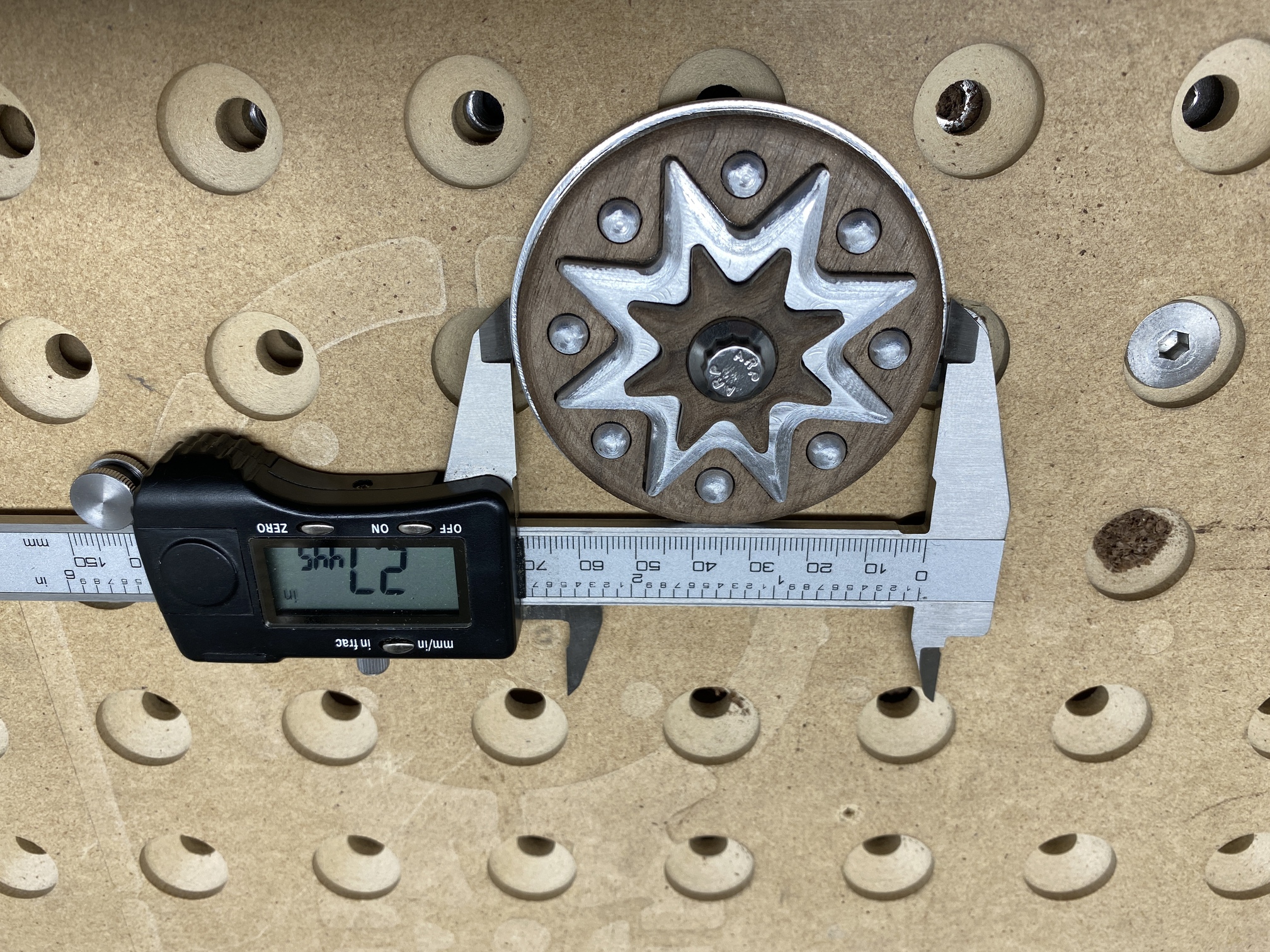
Once I get my part off the machine, I start sanding. A lot of my parts are round with a center hole by design. I attach them with a bolt to a drill and use it like a lathe to easily sand down. Other parts depending on shape, I sometimes use a orbital sander and the rest by hand.
I start out off the machine with 400 grit, then 600, 800, 1000, 2000, 3000, 5000.
Once 5000 is done it is a hazy almost chrome shine. I then start with a buffing wheel with coarse then fine grit polish. After it is done, I wash with dish soap. Then after handling it I finally use hand polish/wax and wipe it down by hand.
For touch ups I use auto spray detailer.
Hope this helps, you can PM me any time.
I have been buying most of my Aluminum from Stoner Metals on Amazon.
If you want aluminum that has been surfaced already to spec search for “Tooling Stock”
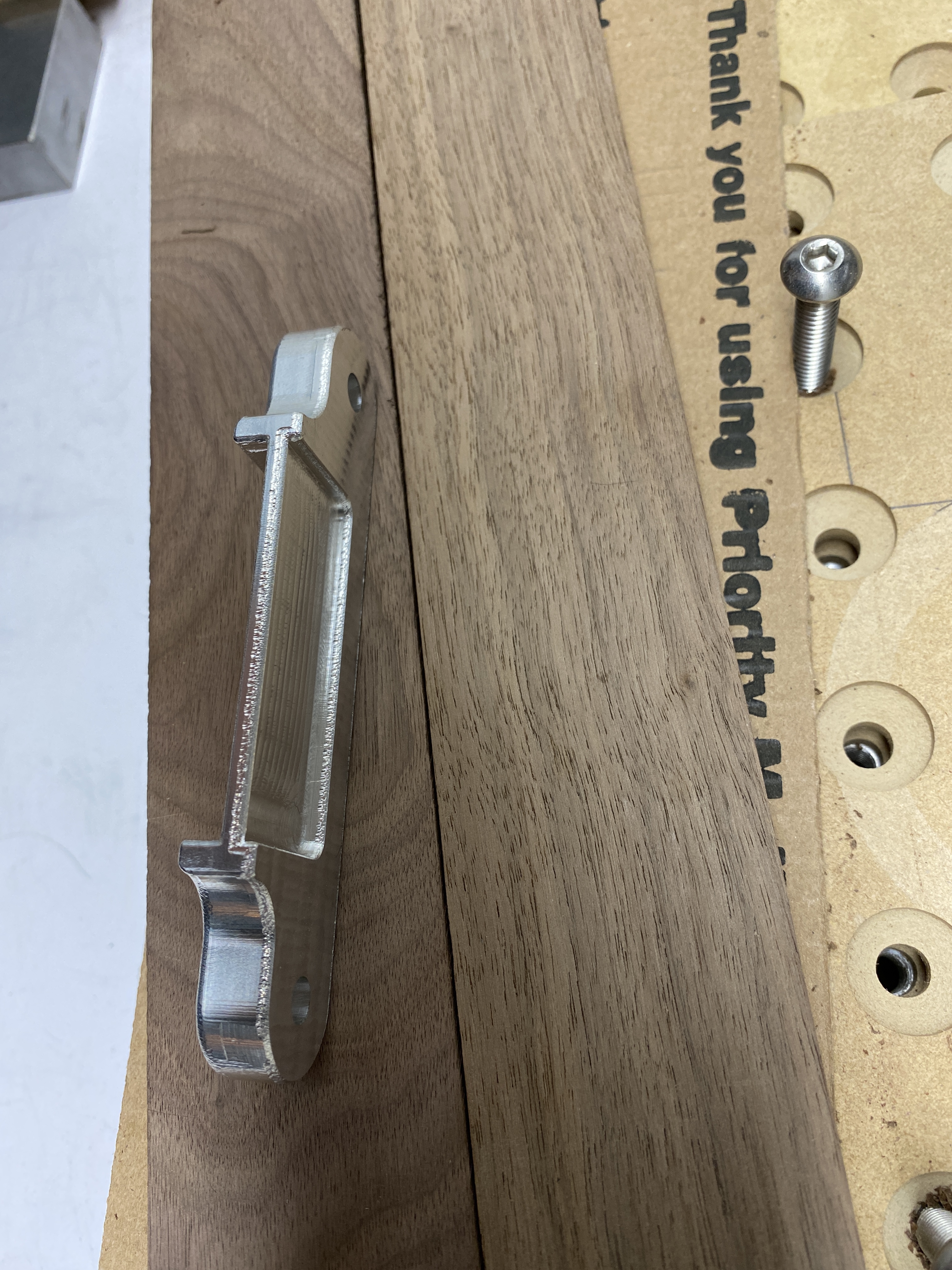
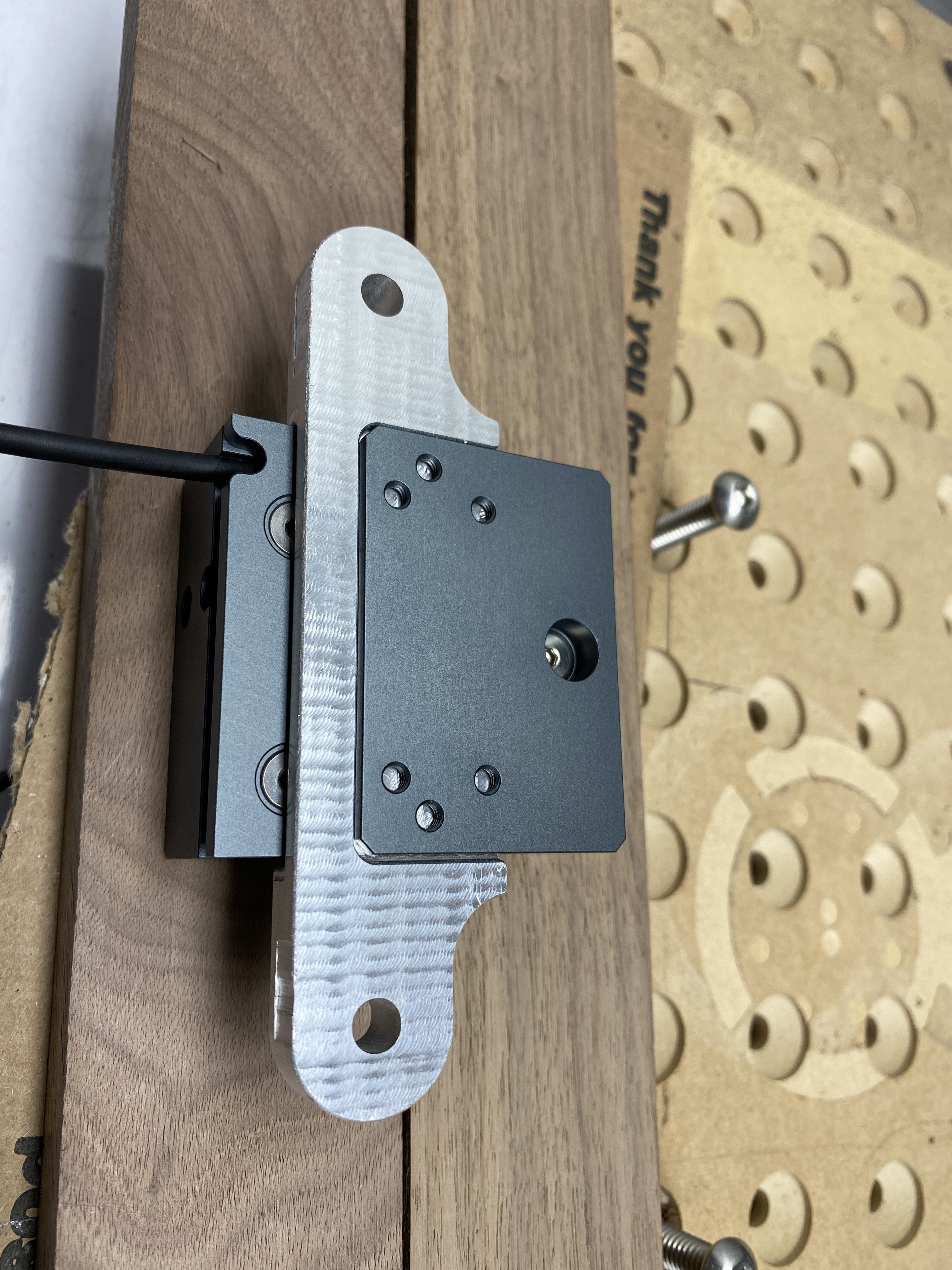
Well, don’t say I didn’t warn you about the aesthetics, here’s the prototypes in a mix of Shapeoko milled and 3D printed, they do not have the design elegance or presentation of those above;
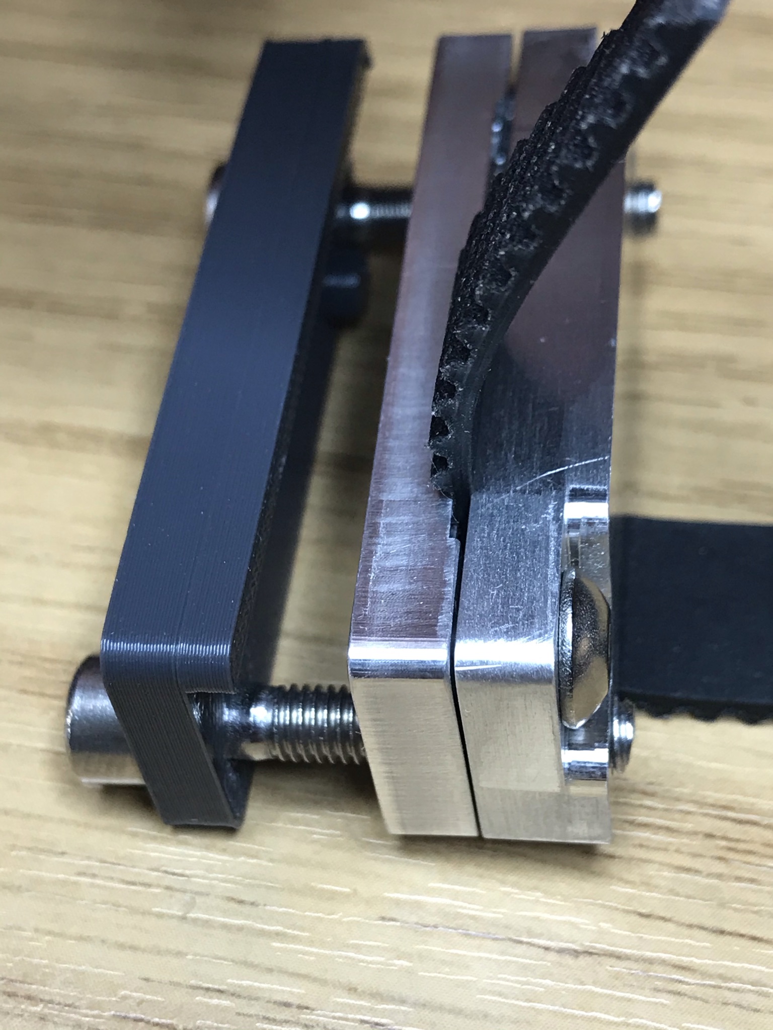
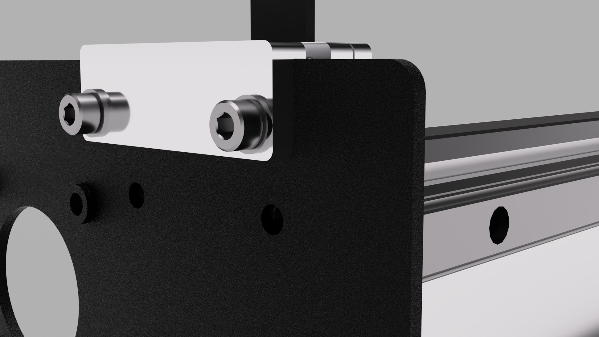
And here’s some Fusion renders of where I plan to make some new holes in my Y plates to mount them, one hole and a belt slot should do it. The clamps occupy the space where the V Wheels will no longer be after the linear rails are installed. This is all based on Dan Storey’s rails design, the design goal is to be easier to set and control tension than the current belt clips.

Interesting design and looks like it will work very well. Also very nice finish work on the aluminum!
-After extensive testing, these are the results comparing Liam’s belts to mine after tensioning.
(100% Joke, not an insult!)
Here is the clamping blocks btw.
GT2 Clamps on eBay

Where do mine fit on your toothy scale? Keep in mind there are no aluminum fillings on mine.
Hah ok great design! A few questions, that would not fit on my stock machine on the inside of the rail, but with a window it would fit on the outside. How to tension though?
Uses the stock plate M5 hole. I made them to send to @Dr.Angus… He reported that they are working well.
Oh but this will fit v wheels? My frame has the V wheel right up next to the belt super close?
I understand, I see it will pull from the inside when tightened.
That’s the issue. If you look up a few posts, you’ll see that I had a Y plate made with a slot. The virus has slowed progress on that machine. My machine has the double M3 holes. Maybe @Dr.Angus will chime in as the beta tester.