Mine are a lot like your design just with the belt path curved to avoid going through the end plate because I don’t have the constraint of the V Wheels. I saw your 3D printed design but wanted to see if I could avoid cutting slots for the belt. Time will tell if this design works or winds me up and gets replaced.
1 Like
The GT2 blocks are cheap, can cut one in half and embed it in your plates, would stop any damage besides the 90 degree bend, not sure what that will do to a belt. Might put a fillet on the sharp edge to give it some curve at the apex.
Great design though!
1 Like
Below is a photo of me tightening my belts before installing my new tensioner.
Ok last tooth joke I promise.

3 Likes
Hah,
Convergent design…
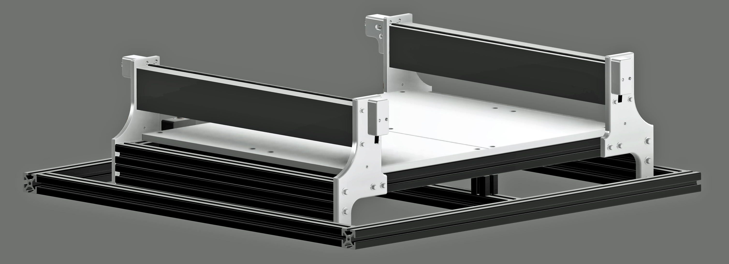
I milled tooth slots for the GT belt into the rear half of the clamp and a 5mm radius on the front half where the belt bends and exits. My working premise is that the GT belts fail on small radius bends when they are repeatedly flexed around them and not just from static strain. Time will tell if this is correct or whether I end up cutting slots in the steel plate.
1 Like
Oh thats awesome, I did not see that. Well done!
1 Like
They’re prototype-y and intended to be easily modified and changed whilst I do some experiments with belts on the machine.
Given the repeatable nature of your design, if the two Y belts are installed with the same number of teeth between clamps you should then be able to maintain an equal extension across both the belts by winding the tensioning bolt out to the same point on both Y axes too (that’s key to keeping the X axis normal to the Y axes across the full travel, if you didn’t see my long vid about belt tension)
One option that the belt through the endplate designs give is the ability to use a force gauge to directly measure the achieved belt tension.
Ideally one would make something like a torque wrench that you could dial in the target belt tension and have it go “click” when you’d wound the belt up far enough. Given your very direct pull design and the use of the bearing it might be interesting to see how well the bolt torque correlates with belt tension?
1 Like
I ordered some metered springs I plan to make a tension gauge that slides under the belt. Adjust belt to your desired tightness, measure the length from end, check the depth on the gauge and repeat on the other side for equal tension.
Did you try using the Gates belt tension app on a phone to measure the belt frequency?
3 Likes
No I never heard of it, will research now. Thank you
1 Like
There’s more about it here;
1 Like
“What did the stepper do to you” haha
1 Like
I’m having a little trouble following the logic here, but I can reiterate that Neil’s design is elegantly simple and it works. Of course, finer-grained control could probably be achieved if holes were punched thru the chasis for a tensioning device mounted externally, but such an improvement is probably overkill for a belt system anyway. I’m just happy that it takes only a few minutes to install instead of a sweaty 20 minutes. You do lose maybe 5 mm of travel but that’s negligible.
4 Likes
Thank you for the lesson, there is a lot more to it then I am aware of. I do not have a background in engineering, and the calculations seem very complex. You obviously spent a great deal of time with that post, extremely professional and informative.
Found it very interesting to measure tension by sound waves!
1 Like
My main goal is to easily be able to check tension, and adjust so both sides are equal. Right now I have one side looser then the other on my Shapeoko XXL and I am dreading playing with the crimp, they always slide back to original spot. To be able to check and adjust regularly between projects while checking the wheels, and level etc. will go a long way toward precision.
4 Likes
Absolutely, making a tool easy and a pleasure to use means you’re far more likely to actually use it. Your tensioners will be much less hassle and therefore you’re much more likely to check and tweak the belt tensions.
Unexpected reductions in belt tensions I suspect are an early warning of belt failure.
3 Likes
Awesome designs! I wonder who is going to incorporate a load cell to directly measure the tension in the belts in the belts first.
1 Like
This looks fantastic @CNCInspiration a lot of people saying it could be simpler… well you could argue that a ferrari could be simpler too!
I think it’s a very slick design, and will allow really fine adjustment of the belts, the standard adjuster definitely leaves some room for improvement
7 Likes
Thank you Jeffrey,
I will PM you as soon as I get them tested and finished. Still have to make brackets for the stock frames and the rear clamp.
1 Like
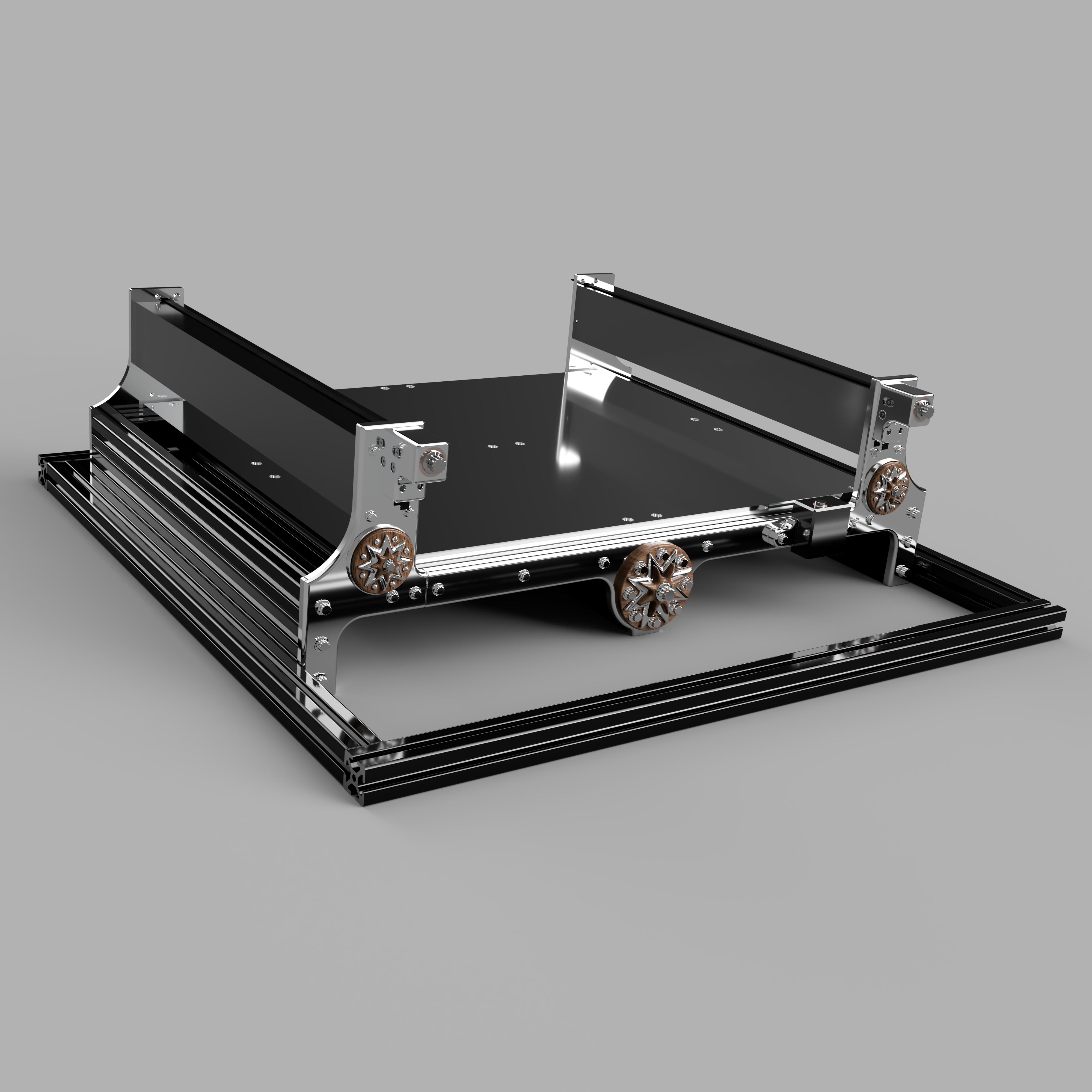
Finished the rear clamp design this morning. I set it up so you can feed the belt in without taking it apart, that way I can hide the bolt heads from behind the frame. Two access windows for the clamp socket cap screws like the front which will have rubber inserts to keep out dust.
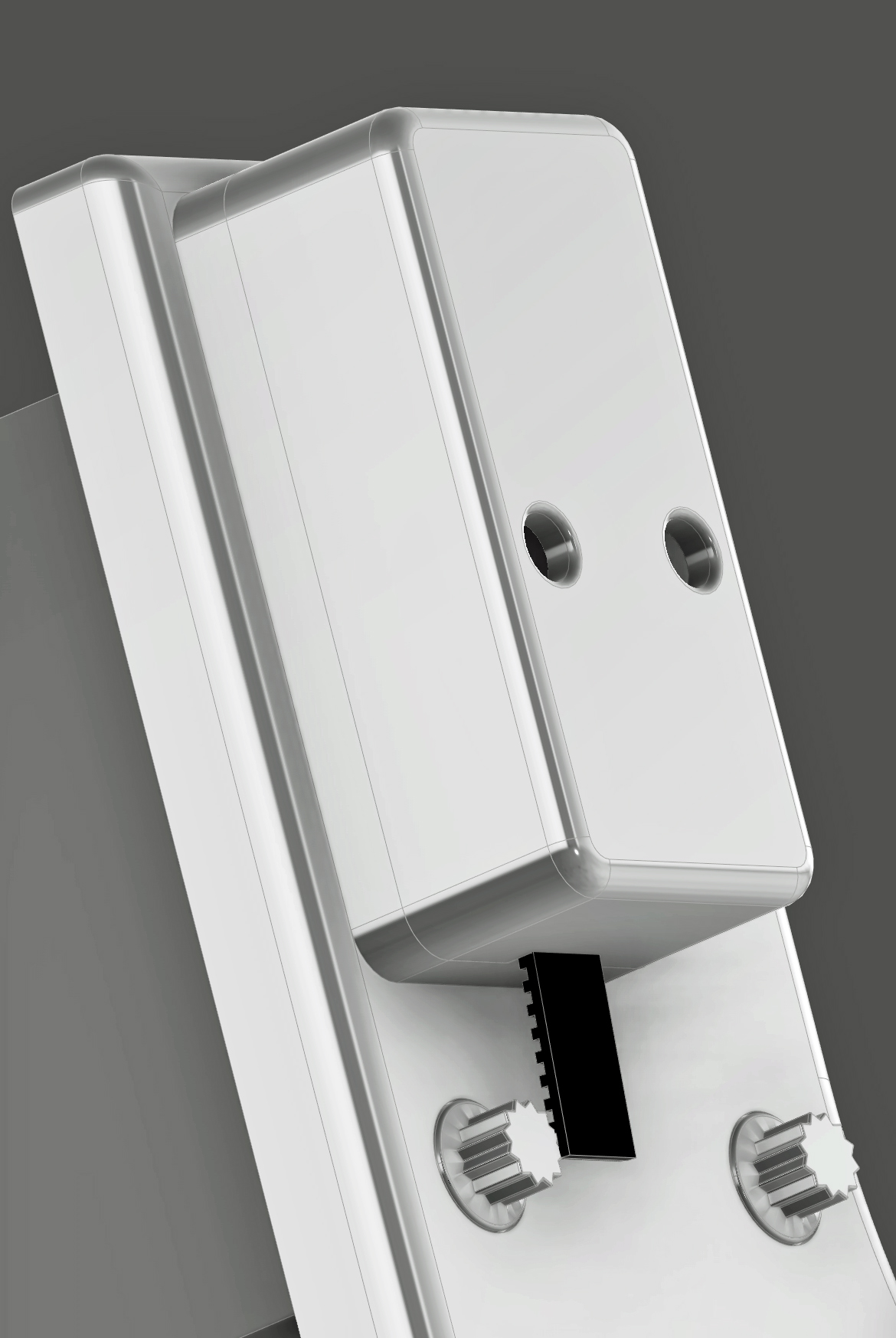
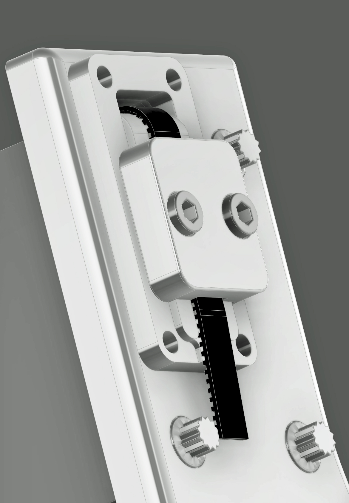
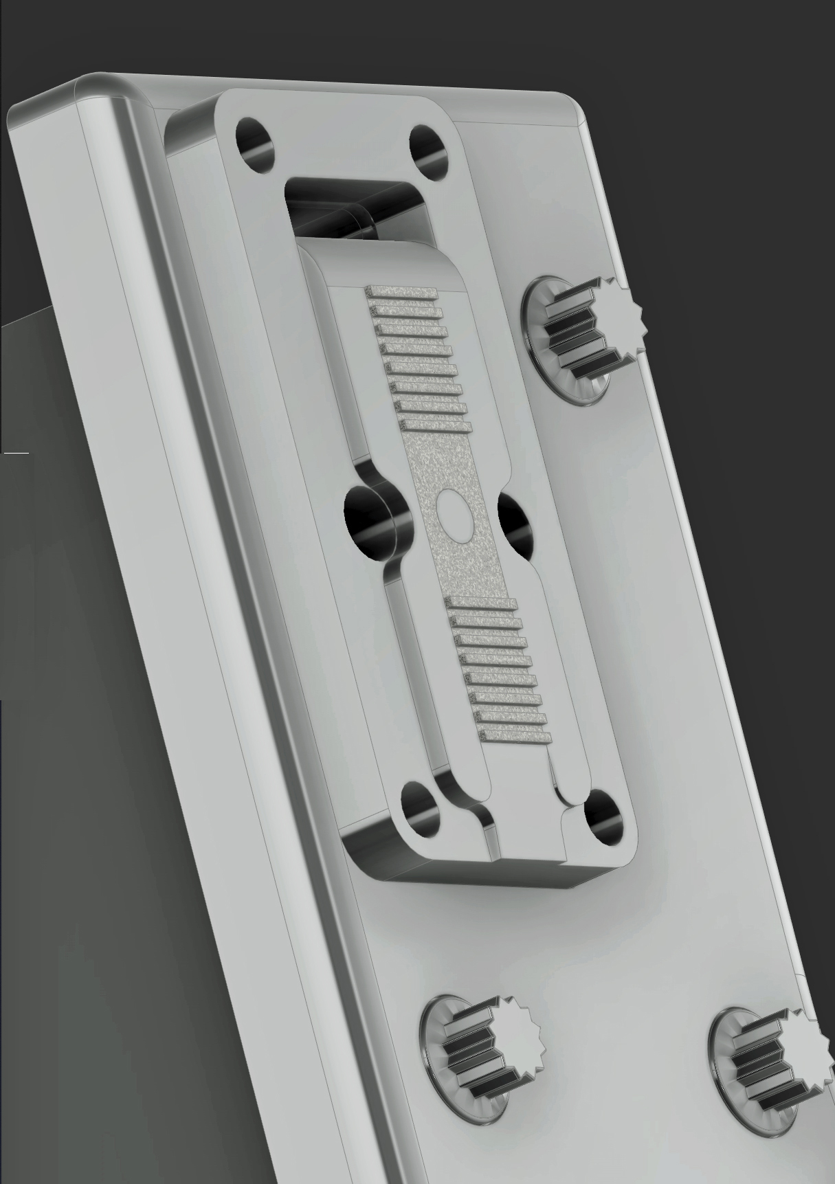
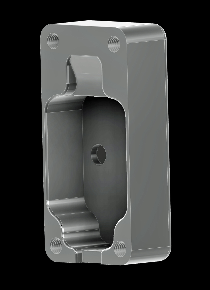

4 Likes
One thing you might want to include on the vertical plates carrying the Y rails are some alignment edges that make it easy and accurately repeatable to measure the diagonal distances for squaring the machine up.
I saw a guy on mycncuk who made up a jig with a dial gauge attached to the end of a long rod which was set to the right length to make comparative measurements the diagonals on his machine down to 0.01mm easily.
Using a tape measure across the steel plates is a PITA
3 Likes