When I mocked up the machine on the 80/20 frame I checked to see if both sides were touching at the same time, and front and back were dead square which was very nice to see. The frame is extremely rigid and very strong. 8020 makes some very precise cuts.
I have an idea to make a custom bracket that could be adjusted to fit between the frame posts with rods that joined in the middle, then have them far enough apart to spread the inside diameter blades on a caliper to measure.
I don’t know how I could notch the frame though for a diagonal. It would be a hard angle to setup for.
Very good idea though, never occurred to me. Thank you!
2 Likes
As a complete novice with this and the importance of correctly tensioned belts (squaring and tramming is relatively straightforward) I would be more than prepared to buy adjustable front and rear clamps to make sure I do get it right. I think the existing design does fall a bit short of the design standards of the rest of the XXL (in my case) and these would be a great after-market upgrade and, in Shapeoko’s best interest, an improvement for future machines.
Of course, there is also the screw drive option?
2 Likes
You HAVE seen this thread…I know you have ![]()
1 Like
I do humbly apologize, because I mistakenly assumed that this “Shapeoko Belt Tensioner” was meant for the common person. There should have been a mention by the OP that this was another thread aimed at those pumped up on steroids and highly caffeinated drinks. 
My mistake. 
4 Likes
It’s FrankenCNCtein!
Just trying to build a better mouse trap here!
3 Likes
I would say the belts are my only real issue with this machine…I have been fighting with just one. I would pay for something better than these silly little clamps…now only if I had a way to make something
3 Likes
Variety makes things interesting, if everyone’s machine was the same who would have anything interesting to post?
I like seeing both the minimalist cheap and the over-engineered uber solutions to things.
5 Likes
I got longer M5x20 vs M5x10 stock bolts to make tightening less of a chore. I guess I risk over doing them now but it’s worth it.
2 Likes
A slightly different contribution to the belt tensioner topic…
Thinking, as is my day job, about how to economically manufacture an improved tensioner, has led me to a design shown below. The idea is based on a) using manufacturing techniques already in use at C3D, b) re-using existing parts where possible, and c) perfection is nice but not essential.

The ShapeOKO chassis only needs a slot adding to the end plates, the lower edge in line with the top of the extrusion. The existing fixing hole for the ‘fold and pinch’ clamp is re-used, but with the tension device outside the plate rather than inside. The mechanism is a small, folded steel ‘chassis’, two of the existing eccentric nuts, a snail-cam lever, two bolts and nuts. I have drawn this to offer up to 15mm belt width.
The process for installing the belts would be: Thread the belt through the slot, around the eccentric pin, and under the snail-cam. Loosen the eccentric pin locking nut slightly, then ensure the eccentric pin is turned to be close to the slot. Pull the belt by hand and close the snail-cam to give ‘first tension’. Tension the belt with spanners on the eccentric nuts. Lock the eccentric pin with the locking nut. Adjust the eccentric nuts as required to give the correct ‘ping’ on the belts.
Thoughts?
7 Likes
The issue, @jepho, of over-tightening was part of my thinking, hence the eccentric range being about 5mm. Cranking up the tightness way too much, if easy to do, might result in first time/inexperienced users causing stepper bearing issues otherwise.
Pull it tight by hand first, followed by up to 5mm of tensioning felt ‘about right’ given this, and anyway a low cost (hint) option to consider as an upgrade or standard factory fitment.
The most practical and simple advice I have seen, audio frequency techniques aside, is that you should ‘just’ be able to get a pencil beneath the middle of the belt with the carriage all the way to one extreme. Ping this and compare the sound to the other side, and adjust one or other to match.
Maybe not sufficiently accurate or calibrated as a purist might opine, but when starting out there needs to be a ‘likely to be near correct’ guide that is uncomplicated to follow.
1 Like
Seems like you are depending on the belt friction against round surfaces too much.
The face of the steel plate is envisaged to be ribbed, and with the teeth of the belt facing this the cam (closing force has to be reasonably high) ought to be able to hold firm.
Critique is the way ideas become good ideas - the more the merrier!!
Great design!
My thoughts:
1 bolt at top will likely leave the bottom flopping. I would think it would need attachments at bottom also.
.2 inches is not a lot of adjustment, might be enough?
Possible tooth damage from splines riding on bolt, sharp bend may damage belt?
The cam is locking the belt down? Is that secure from vibration? Does it crush the teeth or have a clamping block underneath?
Are you using shoulder bolts? They get very expensive. I bought mine from a Chinese vender they were made for 3D printer pulleys so they are cheap. Larger ones jump way up in price.
Maybe a 3d printed sleeve over a threaded bolt, possibly with teeth to avoid damaging the belt and have a wider bend radius. -Cheaper and less belt damage.
Fair comments. Given the steel gauge (envisaged 2mm stainless), I felt that the single fixing might be enough - but experience may tell otherwise. Drilling another hole in the ShapeOKO chassis, over and above the required slot was another factor - those plates are a critical element in the machine’s rigidity and the fewer holes = better. That was the logic, anyway.
The eccentric pin likely does have to be a shoulder bolt, and is what is drawn in the design. I too was concerned over belt teeth otherwise dragging over a threaded surface. I like your idea of a PTFE sleeve, or similar, to a) reduce belt-on-metal issues, b) would allow a regular bolt, and c) increase the radius and therefore eccentricity range.
I do wonder if beneath the snail-cam there could be a ‘GT2’ style plate with an indexing pin into the steel plate to hold it in position, so the cam closes the belt against a well defined GT2 tooth pattern - would improve grip too.
Part of the reason for using the snail-cam, rather than a bolt/screw fixing, is the conundrum that the fixing has to be inline with the belt and therefore makes the clamp much longer, or to the sides and therefore much wider. Trade-offs, trade-offs 
All tiny details aside, it is a very fine piece of engineering. I suggest you make a similar back clamp. Not necessary but would be nice to have a matching set.
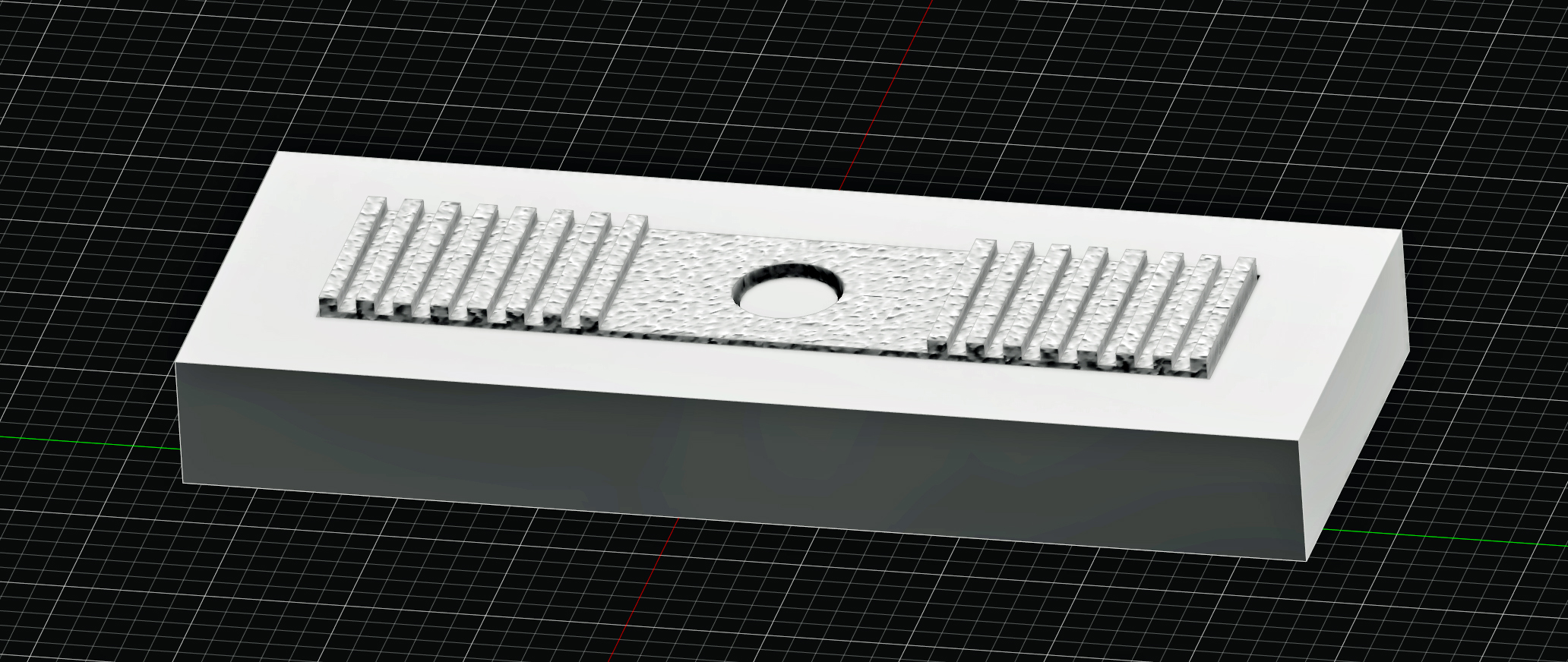
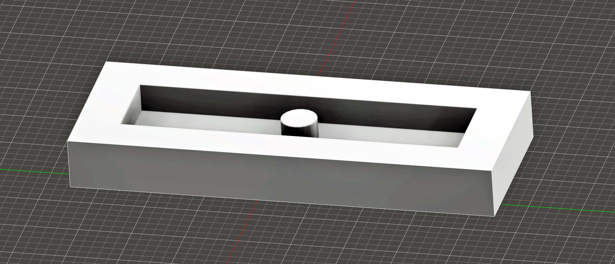
I have designed the rear clamp on my system to allow the GT2 clamping block to fit perfectly.
If you would like the 3D model, to copy that cutout, It should save you some time.
Gt2 Clamping Block Gapped Cutout
1 Like
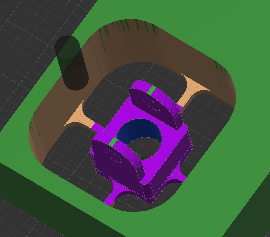
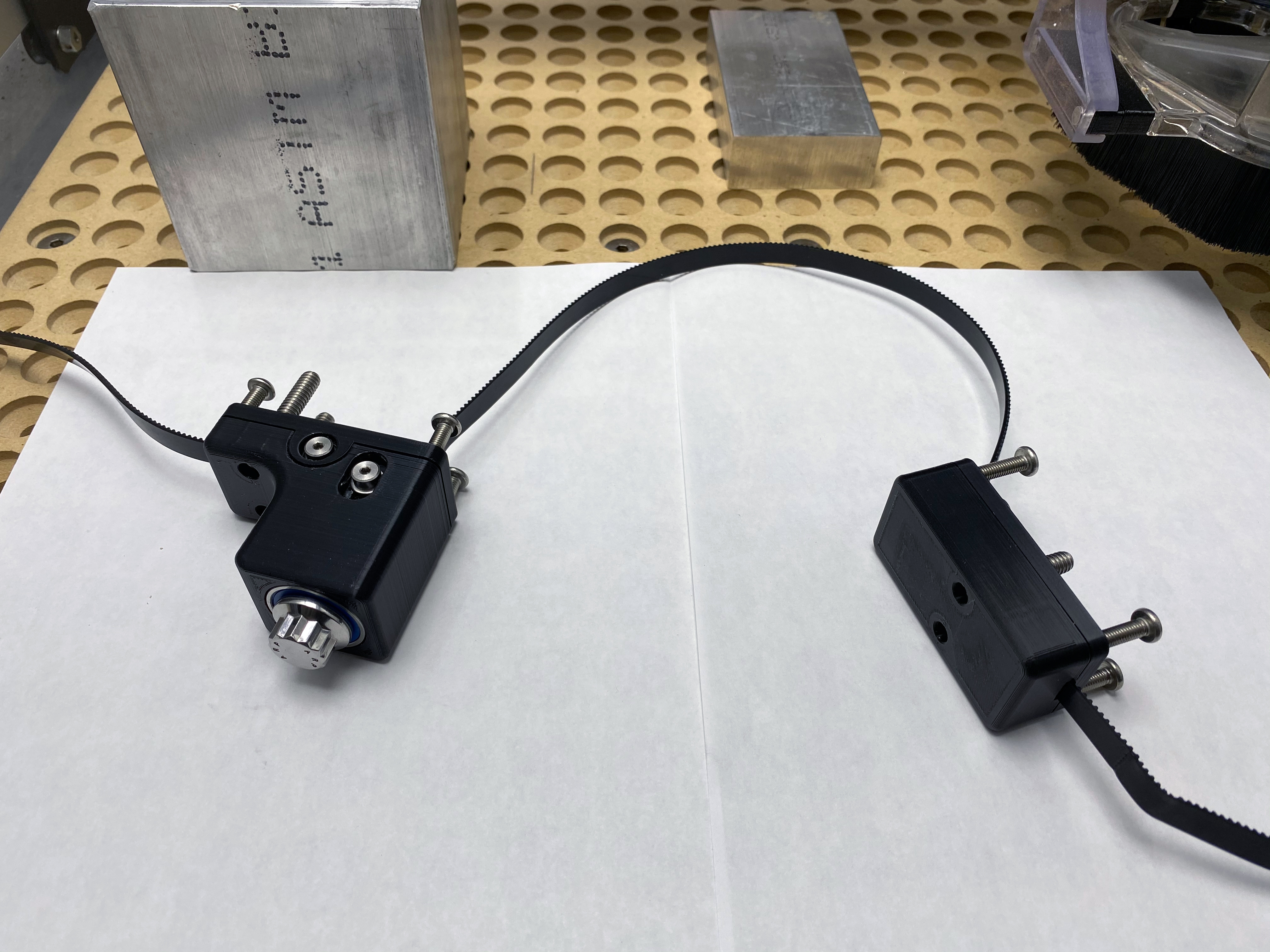
I did some fast prints for testing. Still waiting on some socket cap screws, they should arrive in a few days.
This part will need to be milled out of aluminum (1 inch thick) to be strong enough.
I decided to make an aluminum mounting plate for the front and rear brackets that uses the existing four 6mm bolts to hold the rails on, for the stock frame adaptation. I am mounting mine directly to 3/4 aluminum plate with rear countersunk socket cap bolts that I am using for my 80/20 frames.
1 Like
You are milling that base out of stainless? Why not aluminum, might be easier to cut and cheaper? or is that bent stamped steel? I have no experience with having something like that made, is it expensive?