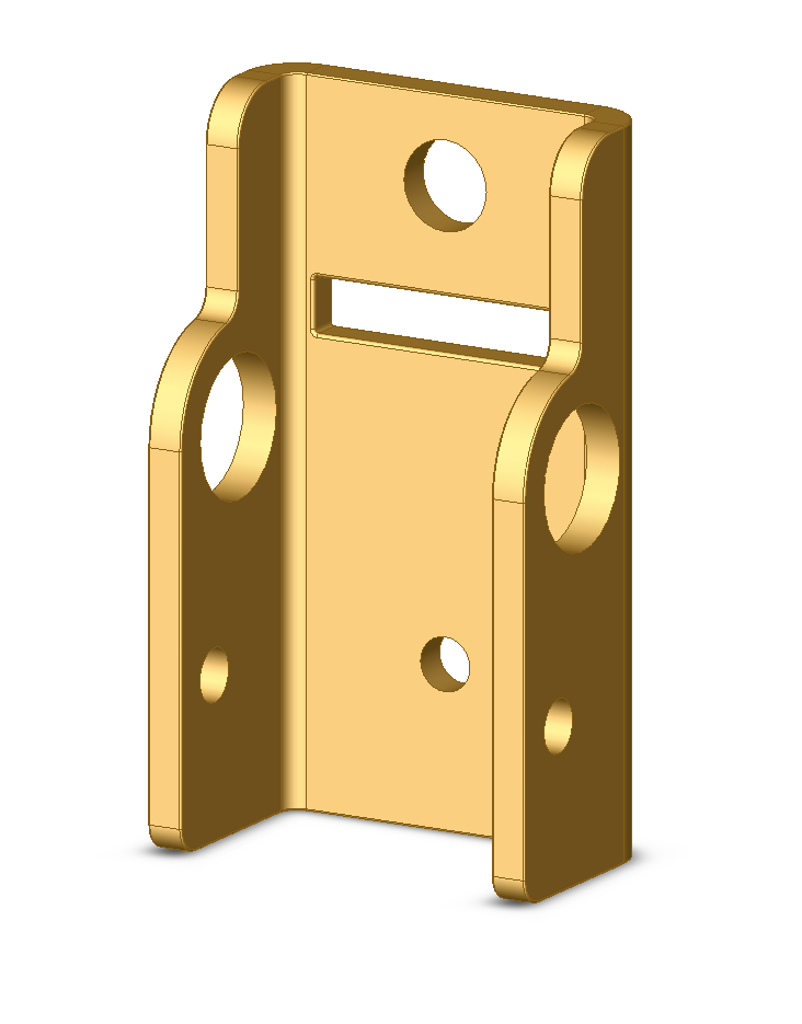
The ‘chassis’ part is folded steel, much like the standard ‘fold and clamp’ parts supplied. Tooling for such a punch and fold part in a relatively tough material (eg: stainless) is not expensive ($2-3k) and the piece parts require very little manual processing aside from tumbling to remove sharp edges, so say $50c ea.
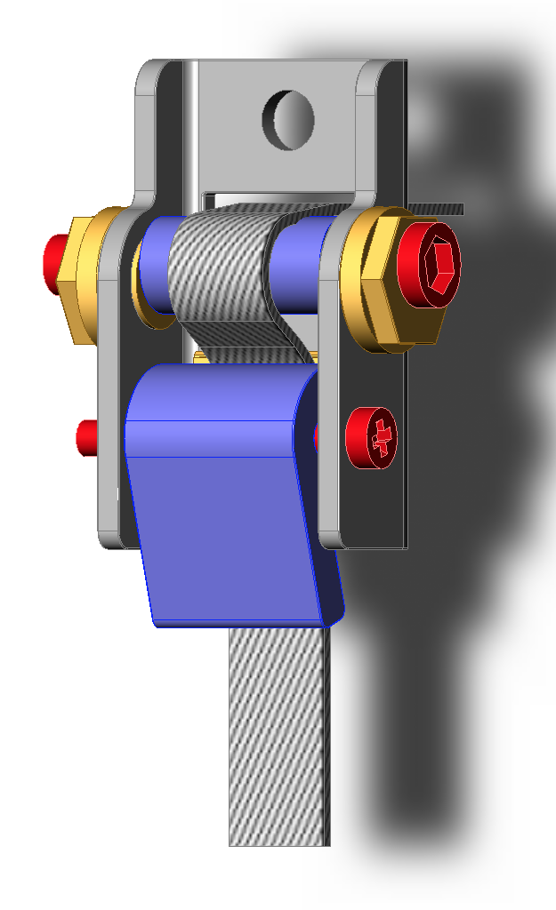
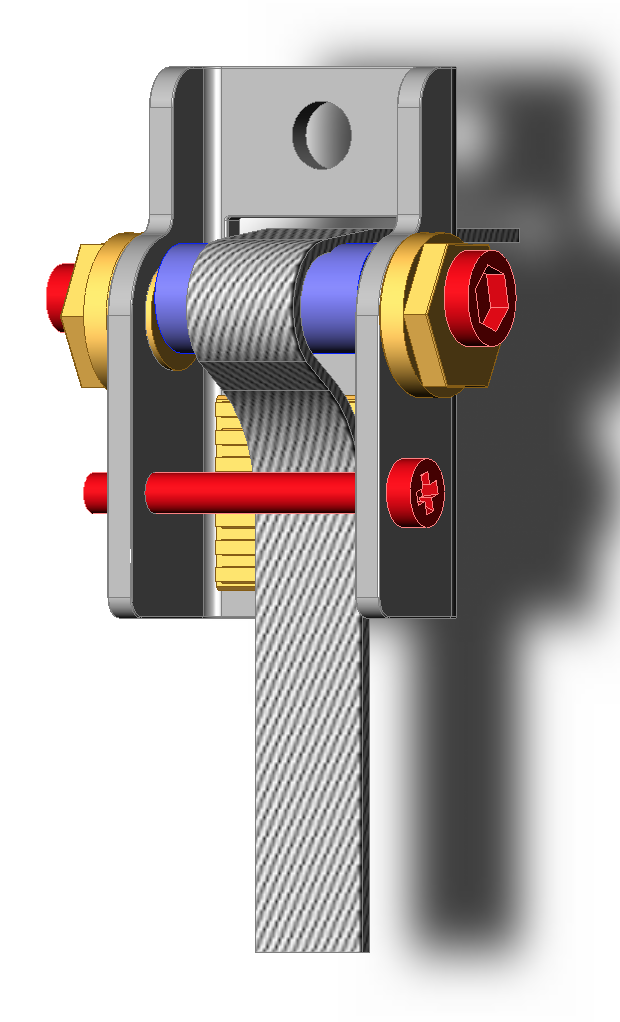
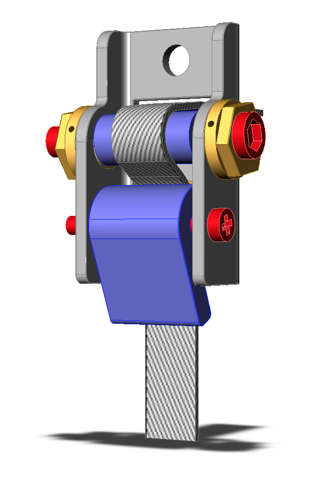
Taking on board the various comments (plastic sleeve over eccentric pin, GT2 clamp base) the idea has become as follows;
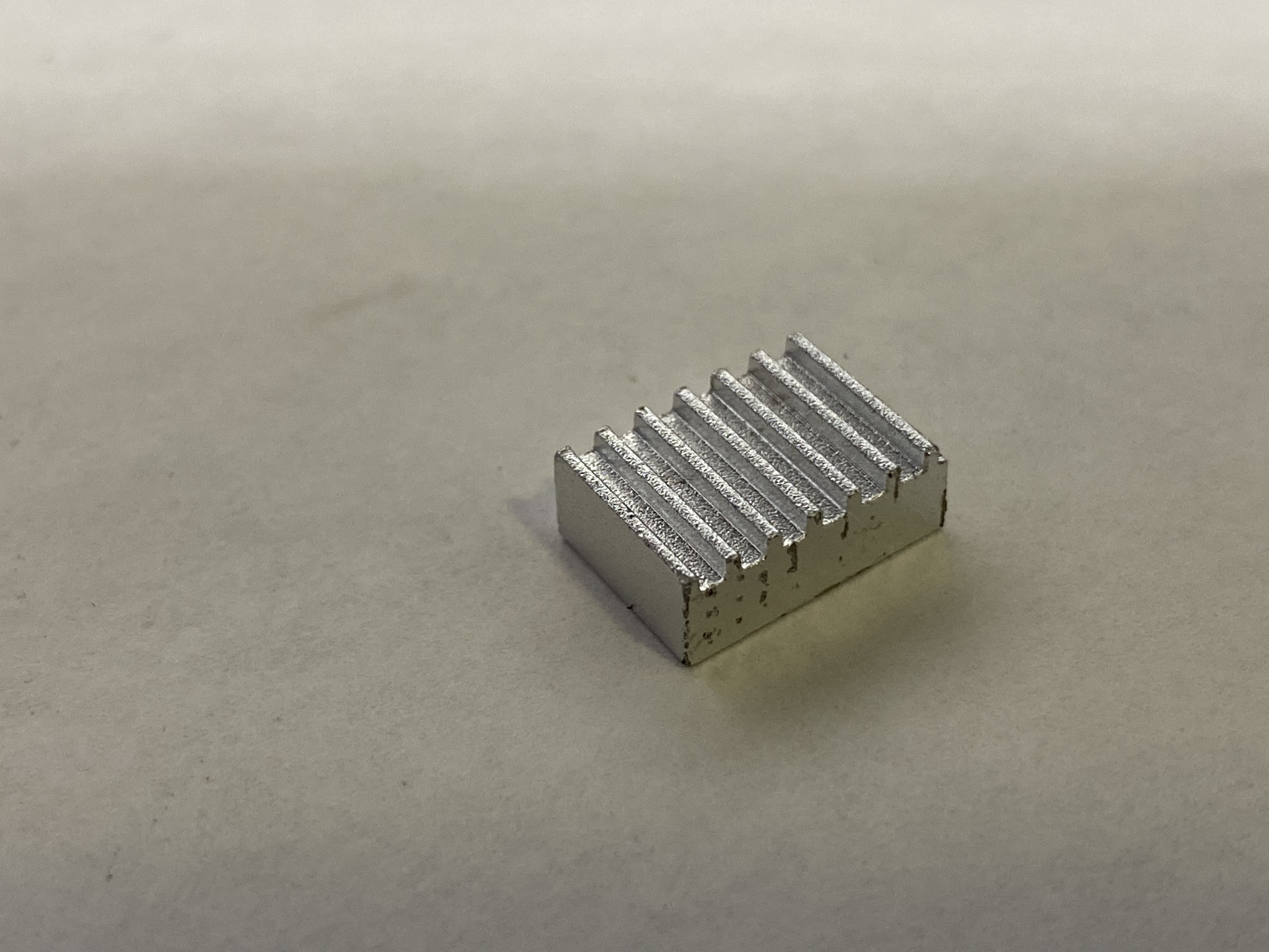
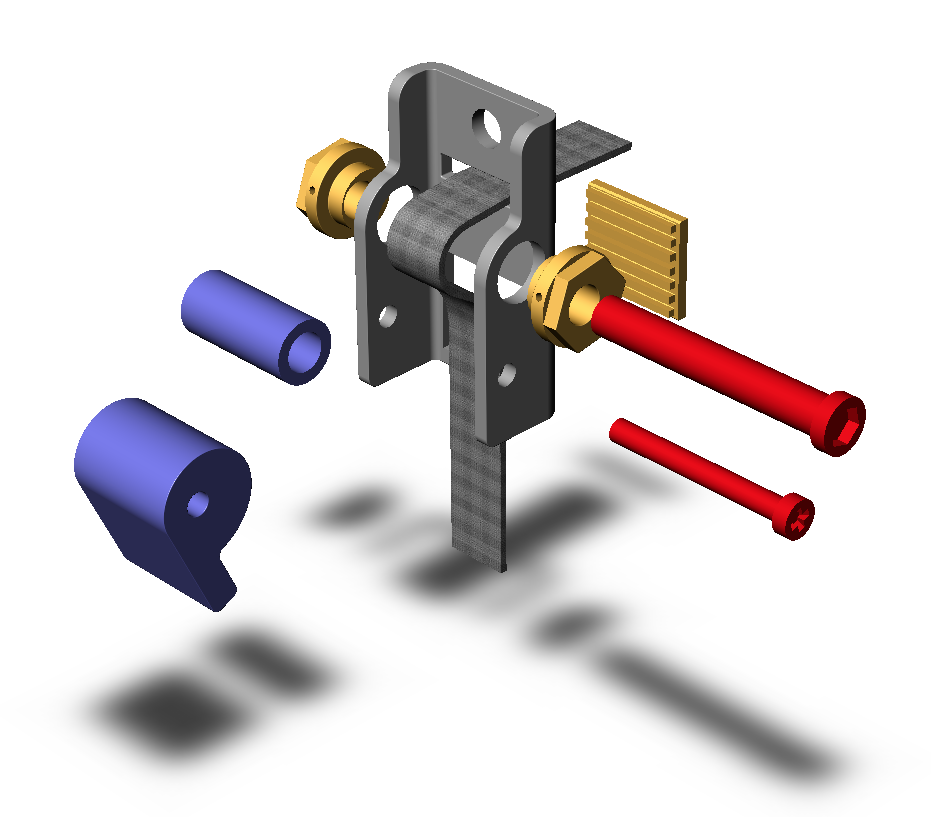
Are you countersinking a tiny bolt to hold the clamping block? It takes a .08 MM bit to carve one out, the teeth are small!
I would think the initial investment of thousands in tooling costs to stamp that metal might be hard to recoup. One of my design constraints was being able to manufacture in house with existing equipment and abilities.
One other issue you might need to address, the belt and top belt attachment bolt hole are so close to the mounting bolt for the rails, your design will be sitting right on top of it. they are button heads so they are not super tall, you might be able to cut out a hole for it to fit inside your part. Looks like it will occur right at the right upper bend point.
Unfortunately my estimation is your upper shoulder bolt is directly on top of the frame bolt.
Picture the force your cam clamp is applying to the bottom of the clamp, I think it would possibly bend the frame and pull it away from the surface.
My 80/20 frame design uses one countersunk flat head socket cap screw for that particular bolt, so it is not affecting the mount.
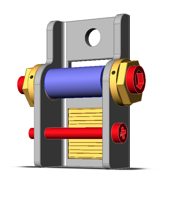
My upcoming design for the stock frame attachment plate will incorporate countersunk 6mm flat head socket caps bolts for the frame bolts, and raise the mechanism from the front of the frame plate by most likely an additional .375"
Also have plans for a aluminum Bitsetter and wire mount attachment below.
Sorry, I misread you are designing this for the pro with 15mm belts or a S3 upgrade to 15’s?
I am wondering about the tooth profile on the new belts are they the same as the 9mm?
I was waiting to get the pro before I started designing for 15mm parts, I am sure the frame bolt profiles and spacing are different. Not sure where to source pulleys and clamp blocks that size either.
My design will take about 20+ hours to fine print all the parts for a pair(front and rear clamp).I have to count it up but I estimate about $30 in hardware on each pair, so 60 hours of printing for each set of 3 pairs to complete one machine, and $90 in hardware. Then I will be doing a detailed milling operation x3 in 1" thick 6061 on each pulley lever, plus drilling and threading and polishing/finishing work, also will be printing a 3d printed jig for precise drilling. Then the four stock frame mount adapters will be milled with aluminum, around 4 hours of machine time, and have 10 dollars in hardware each.
I ordered some 2 inch thick aluminum to make some polished caps, that is a whole other adventure I will post about in the near future I am sure.
Also I would caution to spend a bunch of money up front as I would be careful not to over estimate the interest in a S3 belt clamp, as we 9 people discussing it on the forum might be the only ones interested haha…
I had presumed that GT2/15 was still 2mm tooth pitch, so given that a choice of width had to be made anyway, 9mm or 15mm it seemed sensible to go for 15. If the tooth pitch on the 15mm is different, then the GT2 ‘slab’ could simply be changed for a suitable pitch alternative. I need to look critically at the relative hole positions on the ShapeOKO chassis, the relative ‘centring’ of the 9mm vs the 15mm belt due to a) the vee rail profile on the extrusion and b) the likely pulley position as these will, I think push the outer edge of the 15mm belt further out rather than just fall on the same centre line as the 9mm.
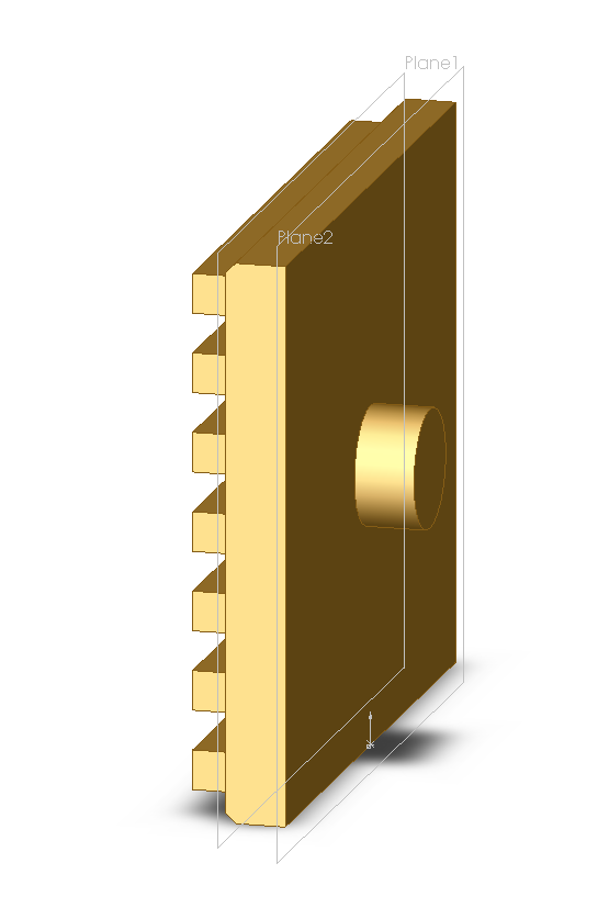
One other option for the belt gripper, assuming the steel plate would be punched / laser cut and then folded would be to simply cut slots in the steel for the GT2 belt teeth to engage in.