Nice idea - a laser cut slot pattern 1mm x 15mm x 7 or 8 slots would be neat and save a component. Punching this pattern would give any toolmaker palpitations - just too fine a geometry to be realistic.
1 Like
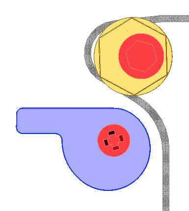
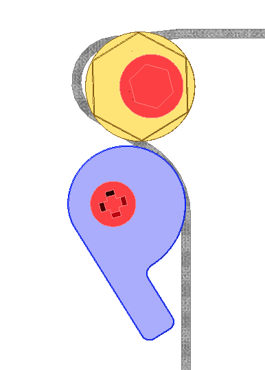
Is your “snail-cam” designed to tighten CW or CCW? Hmmmm …
It’s organised so that the belt ‘pulling back’ tightens the cam. Also so that the cam cannot be forced so hard as to either break it, or damage the belt - it won’t ‘crush’ the belt more than 50% of thickness before the cam action flattens out to constant radius.
3 Likes
Carve the base frame out of aluminum or 3d print it and test it out! If the design has the belt at 15mm the current design will be hanging over the inside of the frame, might want to offset it 6mm toward the center of the rails, or adjust for the 9mm belts everyone is using so it will fit. Just make the base thicker to stand over the frame bolt. Also occurred to me if you put one on the front and back you will double the adjust-ability. I never considered a cam for tightening, I chose two 1/4-20 bolts for my clamp. I am interested to see how it reacts to vibration.
Based on my current prototype belt clips and the GT2 belt tooth profile;
The teeth are quite curved so the slots, if square edged, should be wider than the teeth to allow the belt to sit fully into the slot. In mine the slots are wider than the tooth and I fillet the edge slightly but I’m machining not laser cutting.
You don’t need to match the tooth width because the job is to pre-tension the belt, it is consistently pulled one way so there’s no need to worry about backlash, just retention against a force pulling out.
The belts don’t compress much across the 0.6mm of the main belt (the bit that isn’t teeth) and it’s not friction holding the belt anyway, it’s tooth engagement so the cam only needs to compress down to, say 0.4-0.5mm and stay there to position the belt teeth in the slots to do the job they’re designed for.
The cam doesn’t have to hold against pulling force on the belt, the teeth are doing this job so the normal friction lock cam concerns probably don’t apply.
2 Likes
@neilferreri 's Awesome design uses a relatively small surface of 3D printed teeth that are reported to work very well so that says a lot about the force needed to do the job.
Liam the GT2 nomenclature designates that it is 2mm between center of teeth?
1 Like
-Asked the guy that spent 15 minutes making tiny curved GT2 teeth in Fusion 360 yesterday…
1 Like
Hah 
Here’s my implementation of the tooth profile from the ref drawing in case anyone has a use for it and doesn’t want to work out the weird centre locations of the arcs in the spec;
20 Tooth GT2 Pulley 9mm Belt 6.35mm Bore v4.f3d.zip (441.4 KB)
Yep,
The whole design by Gates is optimised to produce high lateral engagement with very low jacking out forces. It’s also designed for ultra low backlash and to achieve that at relatively low tensions around the pulleys. All in that means that all you really have to do is hold the belt down over some matching teeth and if there’s any pre-load in one direction it will just sit there. The teeth will largely just pull sideways on the slots and are way too deep to pull out without ripping the teeth off.
It’s the belt equivalent of Torx or Allen head bolt replacing the awful Phillips head which just jacks the screwdriver out of the head as you apply torque to the bolt.
2 Likes
I will note that the Phillips head screw coming out was by design — it’s supposed to cam out when fully tightened, that was a feature which Henry Ford wanted for his assembly lines. (and so that he wouldn’t have to pay the patent for the Robertson head screw)
4 Likes
Knowing that it’s deliberately broken somehow doesn’t make me like it any better
3 Likes
The Robertson is a very interesting story.
1 Like
It’s not broken — just misused — any Phillips Head fastener which would ever need to be reversed should replaced.
Hmm,
I’d argue that torque limiting drivers are now so cheap and commonplace that the Philips and flat head drivers are EoL and have been for many years.
Back in the days of early mass production I can see that self-limiting fasteners may have been an economical, least-worst solution. The problem is that the torque limiting they provide is wildly inconsistent based on the tool wear which the design inherently causes and the individual conditions of each tightening. The cam-out forces vary with tool angle, tool wear, fastener materials and coatings and the hold-in forces vary with body position, strength, size and type of tooling used.
Arguably in today’s low cost mass production, for the rare cases where you don’t have a clutch in the drive system to control torque, the Torx type torque limiting of allowing the replaceable driver hex insert to shear is more effective as that doesn’t leave you with a fastener too damaged to remove.
The inconsistent use of pozi-drive and philips is the last straw for me, trying to figure out which partially chewed profile I’m trying to undo is just unnecessary.
</ rant >
3 Likes
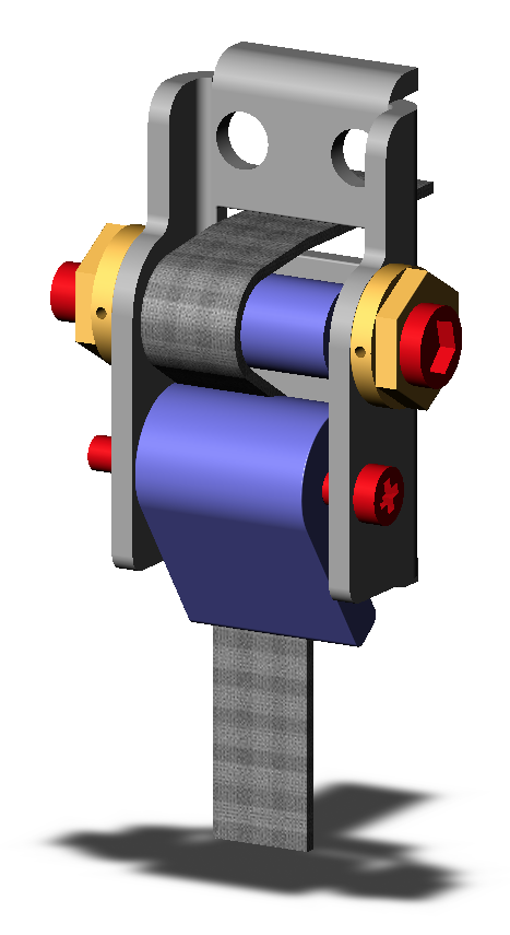
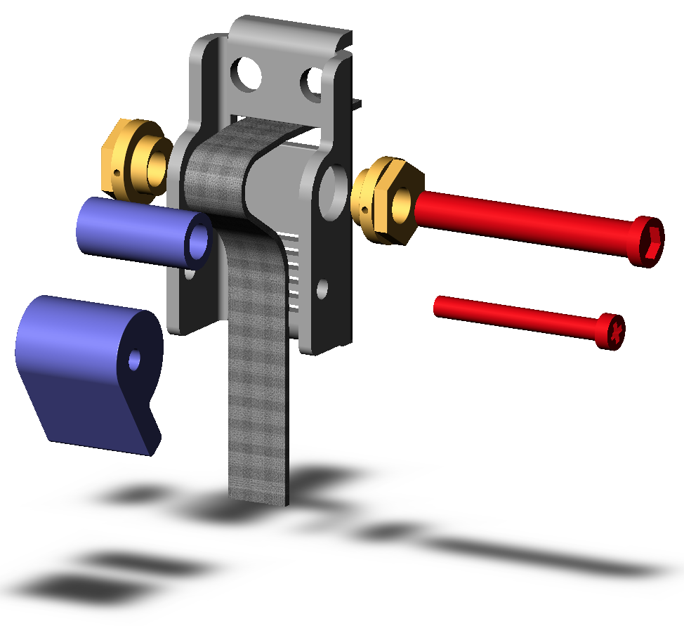
Left and right mount idea added, also ‘almost’ deals with the extrusion bolt head interference. Were this to be tool-punched, I have added a pair of ‘feet’ that would be easy to incorporate (not so easy for CNC machining). Also kept the Philips Head screw as it seems to be pleasing so many
2 Likes
Nice! Now the only other issue I can see is how the center bolt will behave when you attempt to tighten one side then the other, or maybe use 2 wrenches at the same time?
Are you Pozidrive we can’t torx you out of it? The idea of cross head is quite Allen to me, not what I’d hexpect at all.
7 Likes
Hahahah oh man got me on that one.
Phillips is my go to method of attachment hardware. -Said nobody.
Phillips… what I reach for… when there is nothing else available…within a few hours drive.
2 Likes