Approximately an extra 5 lbf on both axes for a 1/16" deflection then? Note that the amount of spindle and bit stickout (their vertical position with respect to the load carriers) will affect the measurements too.
My Makita Spindle is all the way in the mount, bit stick out is 1 3/16in. Measured about 1/16in above my wasteboard which is 3/4in above the OEM wasteboard.
1 Like
To be fair, it only outputs this 0.0002" chipload when the turtle/hare slider is at the minimum (1%), and goes up to 0.001" as soon as one selects at least 15% on the slider. This slider is probably the top reason why I don’t really use GW anymore, since I have yet to figure out what part of this slider range is actually appropriate on a Shapeoko. As you noted, the 1% position might as well be called the “bit burnishing setting”.
If I know anything about me, I will want to experiment to measure actual endmill temperature depending on the chipload & K factor, to be convinced. I wanted to contribute to your K-factor database anyway by doing test cuts in as many different materials as I have on hand, so it will kill two birds with one stone.
Anyway, it seems to me that no matter what approach we take, we end up concluding time and again that anything in the [0.001" to max chipload for the endmill size/manufacturer] range will work, and that more specifically [0.001’‘-0.002’'] is better at high RPMs (while I still believe that at lower RPMs thicker chips are needed, but I have yet to prove it or convince myself otherwise)
You must have been close to having the X-axis stepper slip. Did you check that? What size Shapeko do you have? (My measurements were on the small one with a Makita fully lowered in the current stock mount and about 1/2" thick spoil-board.) So, in light of your measurements, what force would you put into the calculator to come up with an initial feed rate with that stick-out? (This link has some issues, but shows the basic idea.) Is your EasyTram Z plate pink? Do you have upgraded V wheels on all 3 axes? Does/will Carbide 3d sell them? ![]()
The stepper did not slip. I have the Shapeoko XL. The EasyTram is anodized redish (I prefer that to pink). Not all the wheels have been upgraded but the Z have and some of the others. I would like to finish the wheel upgrade but Mr Beaver had run out. Maybe Vince’s upgrade would also address some of the deflection issues.
1 Like
The researchers from the link you provided imbedded thermocouples in the workpiece to measure its temperatures near the cut. The temperatures measured there were around 450 degrees C. That suggests that the carbide endmills that they used were good for temperatures significantly higher than that. Aluminum melts at 660 degrees C. Pyrographers typically use tools with less than 571 degrees C tip temperatures. Most plastics melt at around 200 degrees C. So, why do endmills need to be kept “cool to the touch”?
Regardless, the proof is in the pudding and its nice when you can kill two birds with one stone, even if it may be guiding the lily. I recall @Vince.Fab mentioning an IR camera recently. That seems lot easier than the thermocouple approach.
I’m glad to hear your planning on measuring some K Factors!![]()
Holy Cow! Mitsubishi says their endmill coatings are good to 1300 degrees C!!!![]()
1 Like
How about using an infrared thermometer? It is a lot cheaper, more available and provides a temperature not a graphic depiction.
1 Like
Exactly what I was planning on using, I raided the kitchen a few minutes ago in search from our laser/IR cooking thermometer 
2 Likes
True, I have no evidence that endmill temperature is necessarily bad. Just personal experience from bad and good cuts, BUT that might have been only a sign of rubbing vs not rubbing.
Also, I learned a new saying today (“gilding the lily”) !
1 Like
I found them too hard to keep aimed at the small the moving target.
I’ll try to work in more idioms since you seem willing to lend me an ear! 
Agreed, so it will double as good entertainment, like in the good old days of shooting ducks on TV with the Nintendo gun
Joke aside, what I wanted to do is measure endmill temperature immediately after the end of a given test cut, so aiming won’t be an issue. Accuracy, that’s another problem.
1 Like
5 min of googling and now my next 40 minutes HAVE to go into watching him talk about this :
We’ll see if he mentions thermal considerations at any point
EDIT: the video is awesome, probably the best intro to adaptive clearing I have seen, and the guy is brilliant. But…apart from a few seconds near the beginning, no clear answer regarding chip versus heat. I’ll keep searching.
7 Likes
That video is really dope. Thanks for sharing it. So much to learn and so little time! 
4 Likes
I think the answer is in the HSM chart that he copied from the cnccookbook. That chart shows that heat increases with increasing cutting speed (SFM/RPM) and, assuming that the feed rate was constant (was it?), power until the material starts to melt (as he said the chips become “plastic”). I wonder what happens with plastic! Note that Titanium is also a “non-ferrous metal” but has a melting temperature of 1668 degrees C, so HSM probably won’t work with it. ![]()
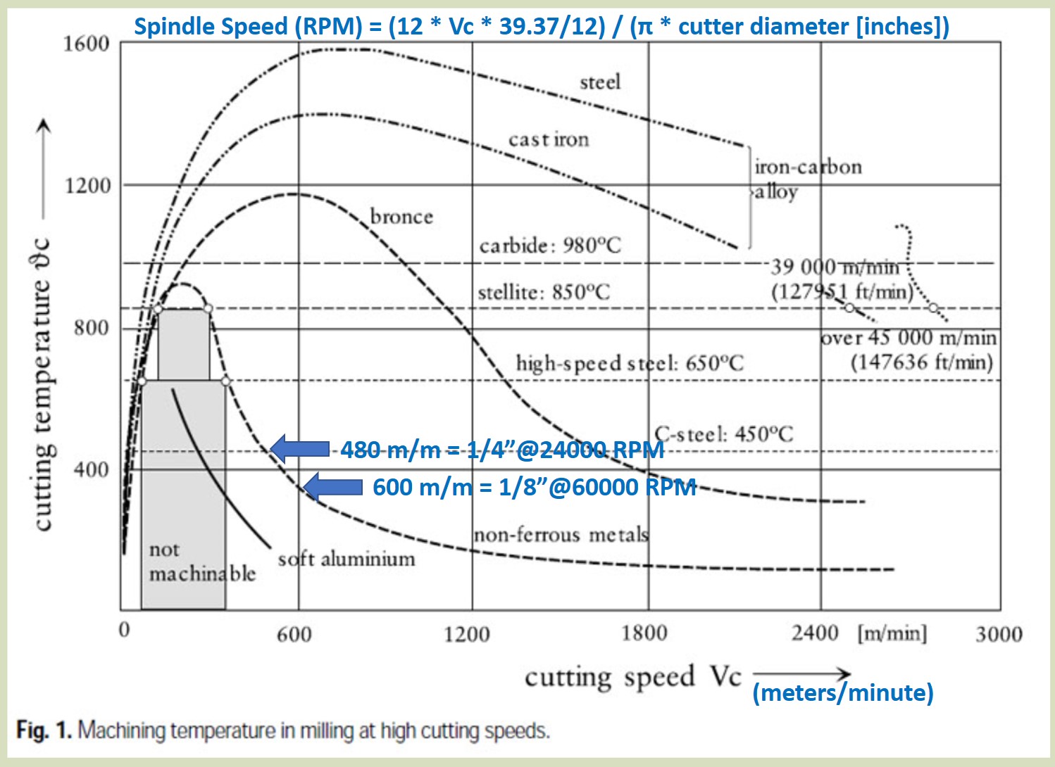
2019-08-29 Here’s an update/correction to BW’s HSM chart from.
~ Twice the spindle speed required for Aluminun but far less for steel and iron!
2 Likes
Well thank you, I had seen that chart before but it had not clicked for me / I had not made the link with the decreasing chipload (assuming, as you mention, that feedrate is kept constant in this experiment)
So at least for metals, at slow RPMs thicker chiploads do help removing heat, and at high RPMs it matters less because of this nice plunge of the “non-ferrous metals” curve that is the root of HSM, so one can get away with small chiploads (and we’re back to the 0.001" rule)
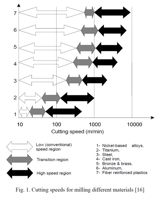
It would be very interesting to see what curves exist for other softer materials, I imagine they only have the first part of the curve (with heat increasing with Vc)
Oh and about titanium, I thought @Vince.Fab used HSM ?
I think its more likely that less heat is generated at the lower feed rates because there’s less cutting power and friction. So there is no contradiction after all. (I removed mention of the contradiction from post 111 to avoid potential confusion.) But maybe that’s the genesis (or oranges as Trump would say) of BW’s misconception?![]()
@Vince.Fab used the Nomad to mill Titanium. It’s limited to 10,000 RPM, so he apparently wasn’t HSMing.
2 Likes
Also used the shapeoko to cut ti adaptive but what the hell, let’s go 100% D in titanium too… even though I like a thicker chipload.
Some metals transfer heat differently and I adjust radial and axial to compensate, but that’s a little experimental
I wonder how it works. Is the cutter softening the material by heating it? Seems like using coolants would be counterproductive too. 
Maybe, but hot wires cut plastic and hot knives cut butter nicely. More experiments for you?![]()