Hi all.
First let me say that I do love my new Shapeoko Pro and I have been using it to cut wood part without worrying too much about this issue.
So now, here is my current issue :
There is a Z difference of about 1mm from the left side to the right side (back to front seems to be fine).
Today I took all of the MDF boards out, check that the hybrid extrusions are properly screwed in.
Swapped the PDF board around thinking some might not all be the exact same thickness.
Then I use the 1/4" probe to zero my Z on the left side using a piece of paper.
I then moved it acros from left to right and I can feel the gap getting smaller and smaller as I stop in each MDF board, and I see the probe slightly digging into the last 2 boards on the right.
I would say the difference between left and right is about 1mm
I tried loosening screws on the left side to try to lower the gantry and on the right side to try to raise the gantry a bit. But nothing helped.
I don’t want to obsess too much about this but if someone has some advice for a newbie to try to address this I’ll be grateful.
I could probably address this by running a fly cutter on the hybrid table but this would not do the whole table for obvious reason and I would still have the issue when I put boards that are slightly bigger than the cut area on the table.
I’ll check all of these as soon as I can.
Table being level shouldn’t “matter” as long as everything else is parallel/perpendicular to the table ? (aka the table on which the hybrid table is on should be flat but not necessarily leveled ?)
But I’ll recheck all of this. When I built it I was on my Skill table and it’s pretty sturdy and flat.
My understanding is that the “most” important is to have the Y extrusion perpendicular to the bed and then make sure the gantry is parallel to the table (and therefore perpendicular to the Y extrusion).
Don’t want to hijack the post but what are your thoughts of removing the leveling legs and sitting the machine on rigid foam
I see a lot do it but I’m leaning towards keeping the legs and supporting the middle of my S3 xxl
William,
My plan is to move the CNC on the sturdy living room table (make of wood and flat/level).
Then loosen all bolts.
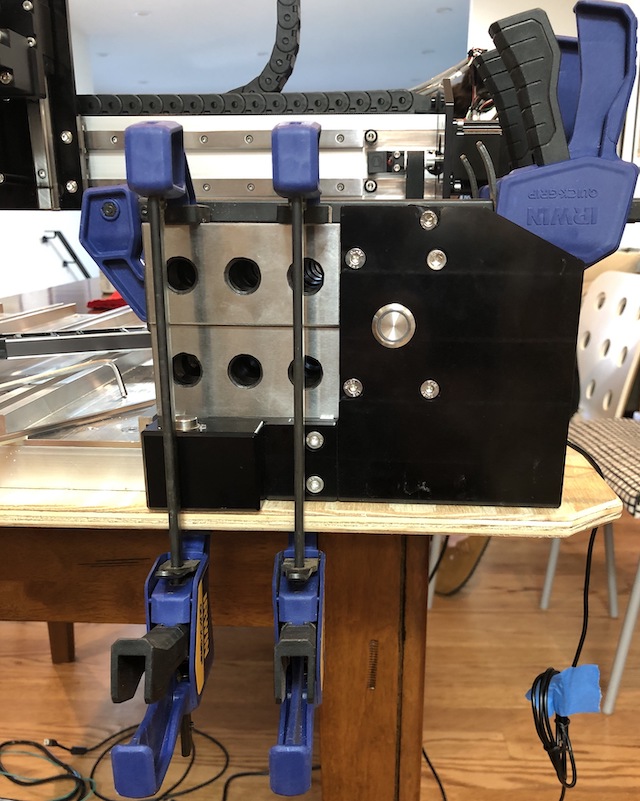
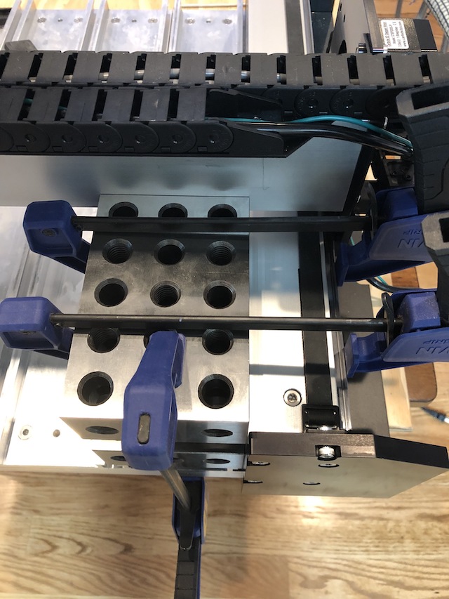
I will use 123 and 246 blocks and start by squaring the end plate and Y-axis extrusions to the hybrid table (after removing the MFD slates ).
Then from there use the same method to square the X-axis extrusions (gantry) to the Y-axis extrusion and the hybrid table.
Then verify that the carriage is also square to the gantry.
Hopefully this will get me where I need to be.
Does this sound reasonable ?
Some of thew 12mm M6 seem to have slightly striped the extrusion holes and I replaced one with a 20mm long that is now tight and not moving (I have 3 more to replace as 12mm seems a bit short in some cases).
I won’t be able to do this before next weekend as this require me to commission the dining table (my wife is very understanding and supporting of my hobby …within some limits ).
Regards,
Rodolphe
So I spent the afternoon squaring everything.
I started by making sure that the aluminum part of the hybrid table was flat : it was
So I had my starting point.
I then squared the end plates and the extrusion in relation to the hybrid table :
I did all 4 corners like this.
The I check the gantry squareness. Also good.
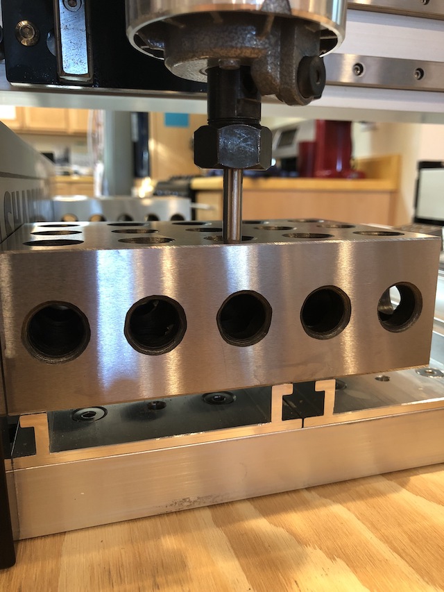
I then checked the gantry level in relation to the hybrid table and there was some adjustment needed.
I started by using a laser level to get close then fine tune using the probe bit in the router and going to all 4 corners, adjust, rinse, repeat :
I also took time to make sure the router is squared. Did some more adjustment.
I then re-installed the MDF slates and did the same test as with the 246 block… ALL GOOD !!
A this point when I move the probe across after using the paper method on the left to set it almost touching the MDF and move to the right, no more difference.
I want to thank you all for your advice and Carbide 3D for the great support
Next will be to do a cut of 1/4" Red Oak PureBond Plywood where I really ran into this problem (previous job were on 1/2" and 3/4" plywood so it was not a big issue).
 (my wife is very understanding and supporting of my hobby …within some limits
 ).
).