Sloping on Z axis

I’ve got a Shapeoko 4 Pro. I understand that Carbide Create does not handle Z axis slopes. However…

If I add a Z to the CC created NC file like illustrated below, will that accomplish that? Meaning will my CNC blow up, crash or do other nasty things?

(Toolpath: Contour Toolpath 5)
M03S10000
G0X-0.1492Y2.7707
Z-0.1902
G1Z-0.2500F8.0
X-0.1718Y2.7726F20.0
X-0.1945Y2.7742Z-0.1890
X-0.2171Y2.7756Z-0.1880
X-0.2398Y2.7767Z-0.1870
X-0.2624Y2.7775Z-0.1860
X-0.2851Y2.7782Z-0.1850
X-0.3078Y2.7785Z-0.1840
X-0.3305Y2.7786Z-0.1830
X-0.3532Y2.7785Z-0.1820
X-0.3758Y2.7782Z-0.1810
X-0.3985Y2.7775Z-0.1800
X-0.4212Y2.7767Z-0.1790
X-0.4439Y2.7756Z-0.1780
X-0.4665Y2.7742Z-0.1770
X-0.4892Y2.7726Z-0.1760
X-0.5118Y2.7707Z-0.1750
Z0.2500
M05

I don’t believe your code does what you want:

If you’ll let me know what dimensions you want, I’ll work up an example file.

Thanks in advance. Most likely using 1/4" ball nose for the cutting, but that’s a future issue.

Work Piece is 9.00" Square
Cutting a circle 7.75" diam
Circle Height at back 0.5"
Circle Height at front 1.0"

If I can actually do this I’ll be thrilled. Hoping that I can use Excel to do point calculations and ultimately push that into NC file.

First, let’s draw this up:

Naturally, the first thing to do is to pocket down to 0.5":

Next, we draw up the profile:

Then we will need a series of lines which are inset from the edge by the radius of the tool — we’ll use a #202, so 0.125":

For the lines, we’ll use a Linear Array:

and we’ll dupe this and move the dupe off to the side and do Trim Vectors on each:

Those line lengths will give us the depth assigned to each line.

Repeat to get the shortened lines:

OK

Select each line from the angle to get the needed depth:

(note that each toolpath needs to start at a depth of 0.5" and then cut deeper by the noted dimension)

Repeat for each until one arrives at:

(messed up the dimensions a bit, so there will necessarily be some adjustment)

At this point, one has to ask — are you sure you wouldn’t want a license for Carbide Create Pro and to just do this in 3D?

Attached as a v7 file.

ramped_circle_3D_v7.c2d (572 KB)

At this point, we want a programming system with a loop — we start with one line:

and we assign a toolpath:

And we export the G-code, and open it in a suitable 3D G-code previewer:

(Toolpath: Contour Toolpath 59 VERTICAL)
M03S18000
G0X4.5000Y8.2500
Z-0.4902
G1Z-0.5010F12.0
Y0.7500F60.0

Go ahead and run that:

Edit the two coordinates:

(Toolpath: Contour Toolpath 59 VERTICAL)
M03S18000
G0X4.5000Y8.2500
Z-0.5
G1Y0.7500Z-1F60.0
Z0.2500

to get:

Now it’s just a matter of repeating that latter toolpath w/ a suitable stepover and begin/end points, and begin/end depths.

Thanks.

I’ve got the PRO version. So far I’m sturggling to make any progress with 3D. Perhaps my 83 years are beginning to extend my learning curve more than I want to admit. Maybe it’s more than “Perhaps”!

Will dig into what you sent in a day or two.

Okay, to model this in Pro you will want to make the working area markedly larger:

Then position things to take advantage of this:

Then draw in geometry sized to allow the angle to be modeled:

Then model the stock:

to the height of the ramp:

Then subtract the angle:

Then restore the material around:

Are you trying to make a circular pocket like Will demonstrates? Or just a sloped circle?

You can use circular/helical interpolation (G2, G3) commands to cut a sloped circle…

(Design File: slanted_circle.nc)
(stockMin:0.000in, 0.000in, -0.500in)
(stockMax:9.000in, 9.000in, 0.000in)
(STOCK/BLOCK,9.000, 9.000, 0.500,0.000, 0.000, 0.500)
G90
G20
G17
(Move to safe Z to avoid workholding)
G53G0Z-0.197
(Toolpath: Contour Toolpath 1)
M05
(TOOL/MILL,0.125, 0.000, 0.000, 0.00)
M6T102
M03S10000
(PREPOSITION FOR RAPID PLUNGE)
G0X4.5000Y8.3750
Z0.0098
G1Z-0.5000F8.0
G3X0.625Y4.5Z-0.75J-3.875
G3X4.5Y0.65Z-1.0I3.875
G3X8.375Y4.5Z-0.75J3.875
G3X4.5Y8.375Z-0.5I-3.875
G0Z0.5
M05
(Move to safe Z to avoid workholding)
G53G0Z-0.197
M02

1 Like

Essentially trying to make an inclined flat hoop.

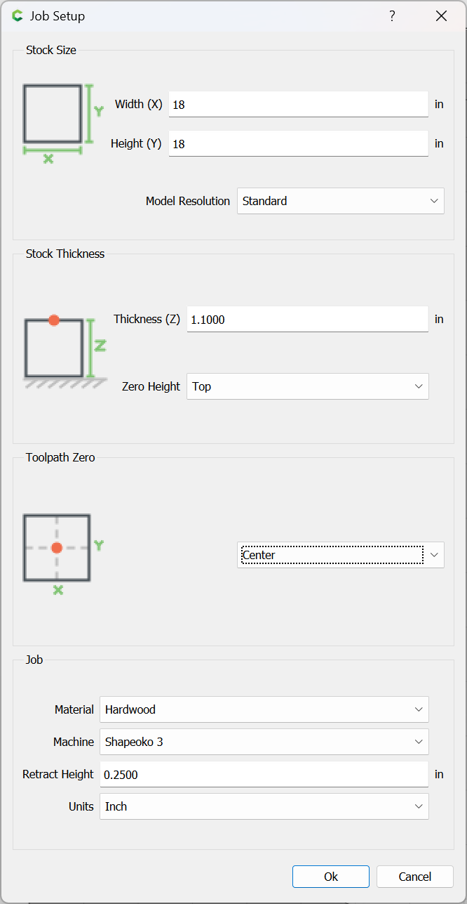
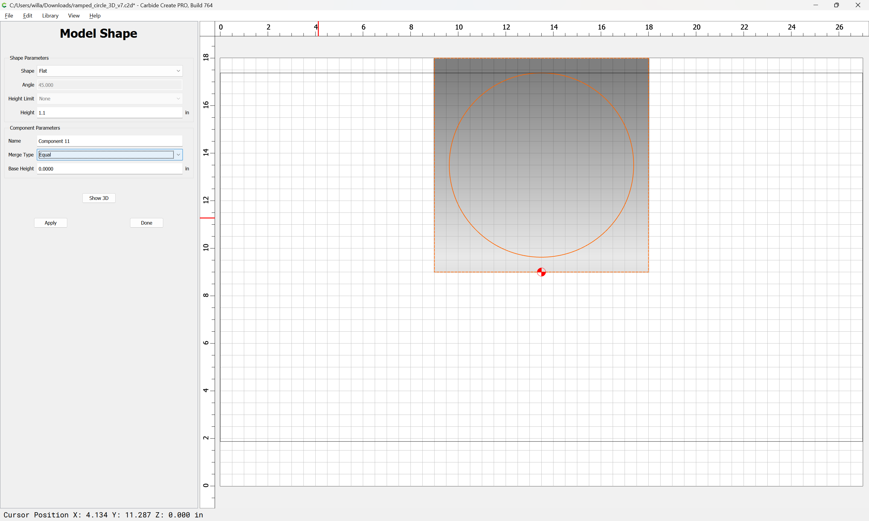
In total, what I’m trying to do is create a round wall plaque based on the attached PNG. I bought a package consisting of JPG, PNG and SVG file. Found out that the SVG would work great for a 2D line drawing. My goal is to give the think some physical depth. So for the past week I’ve been heavily tweaking that and creating lots of Tool Paths. Assuming 1.5" board, The stuff in front of the house goes into the wood about .25". Elements of the house go a little deeper and the roof is set to .40". The tree and other stuff on top of the roof and around .75 deep. Eventually the sky is probably 1.1" deep.

I’m used to designing stuff in TurboCAD and can generally create whatever I need there and then send it to CC via SVG files. It looks to me as though if TurboCAD did an STL export I might be able to pull that into the Model function. Unfortunately my version of TC doesn’t do that. Big surprise.

1 Like

Will:

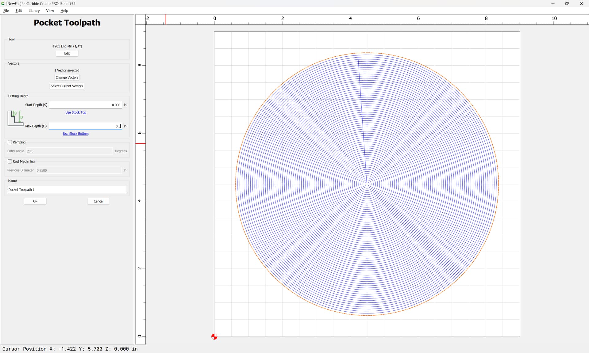
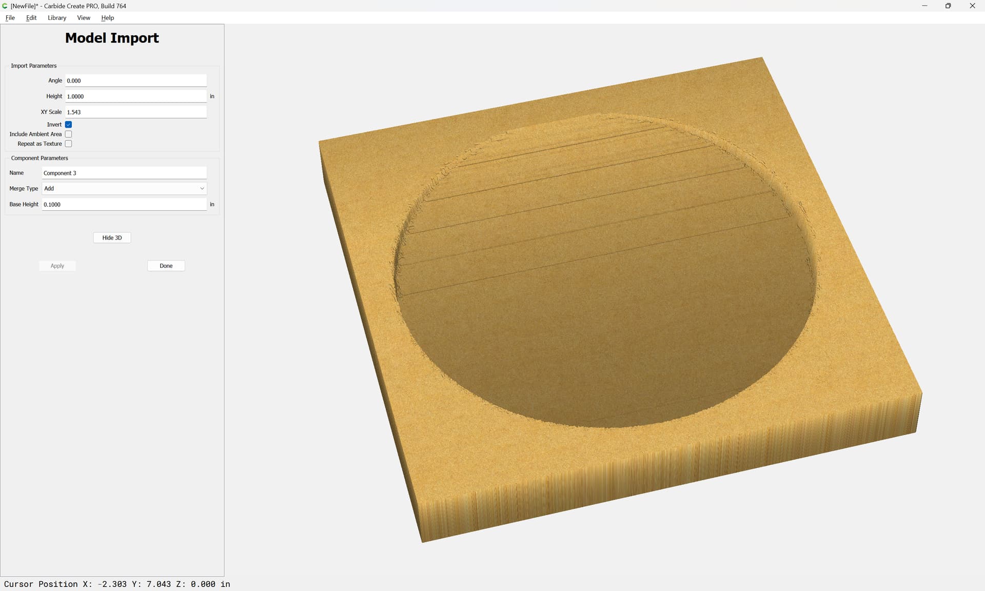
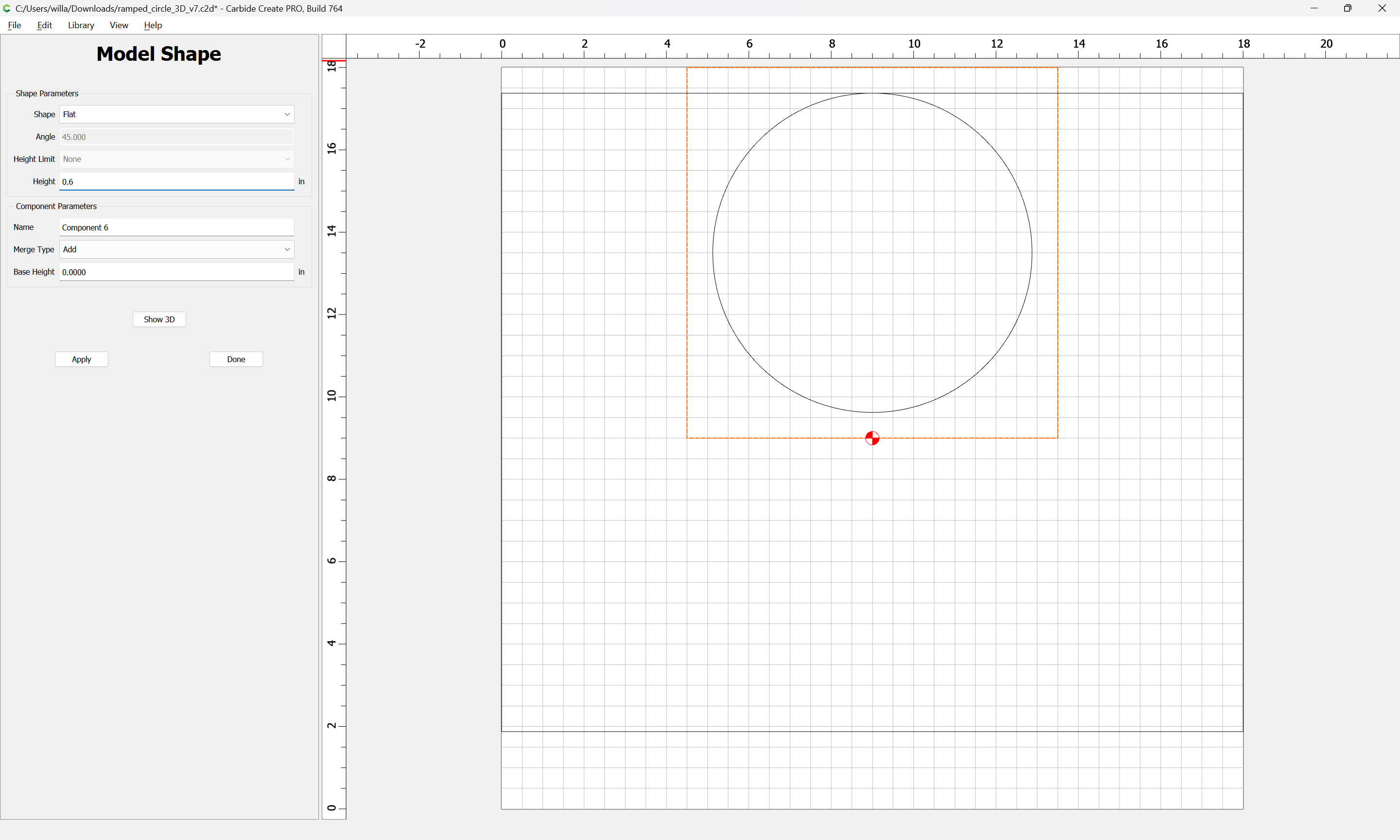
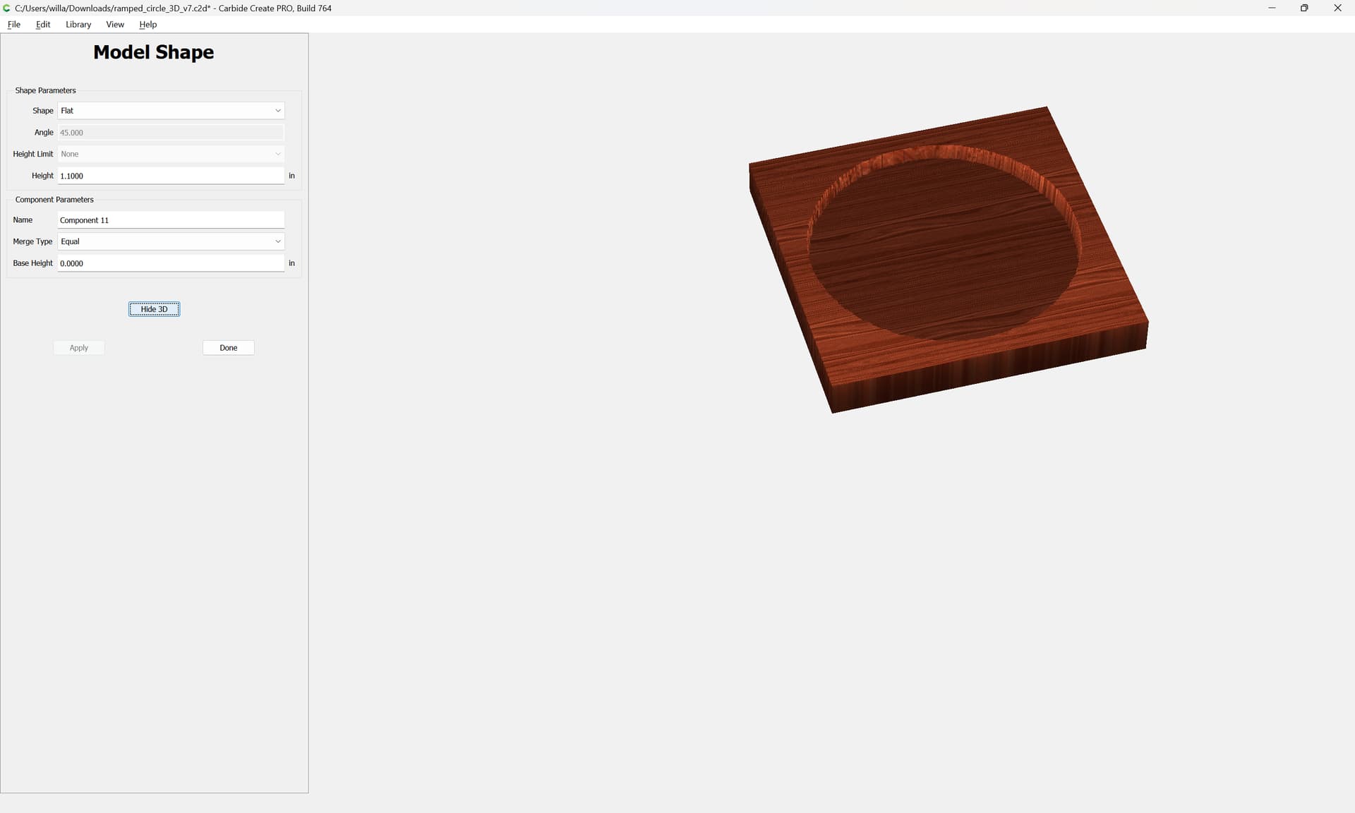
Hate to be dense but here I go. I tiptoed through your Model example and not surprisingly eventually got exactly what your example showed. Hurray. It appears to me that the center disk is what tilted. True?

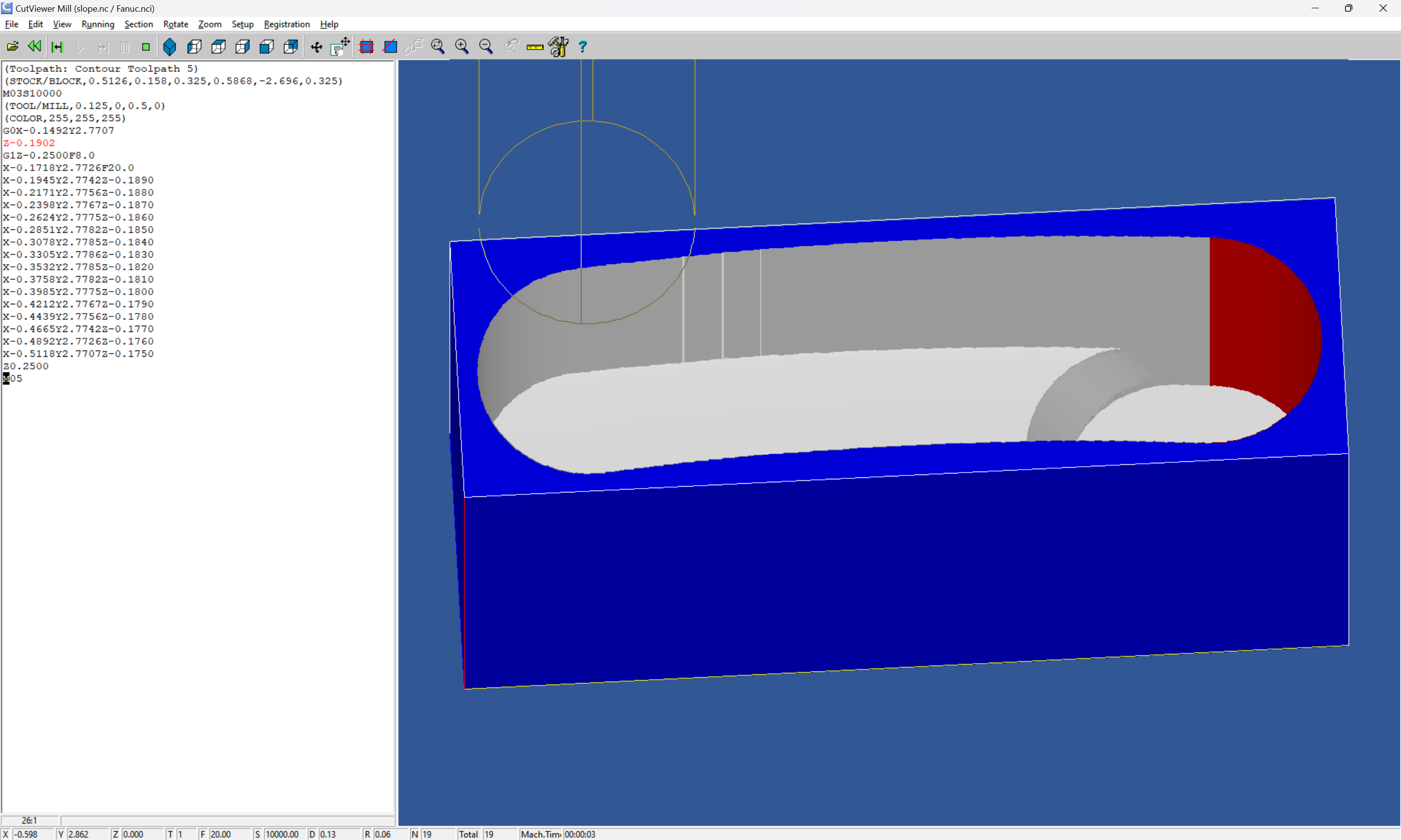
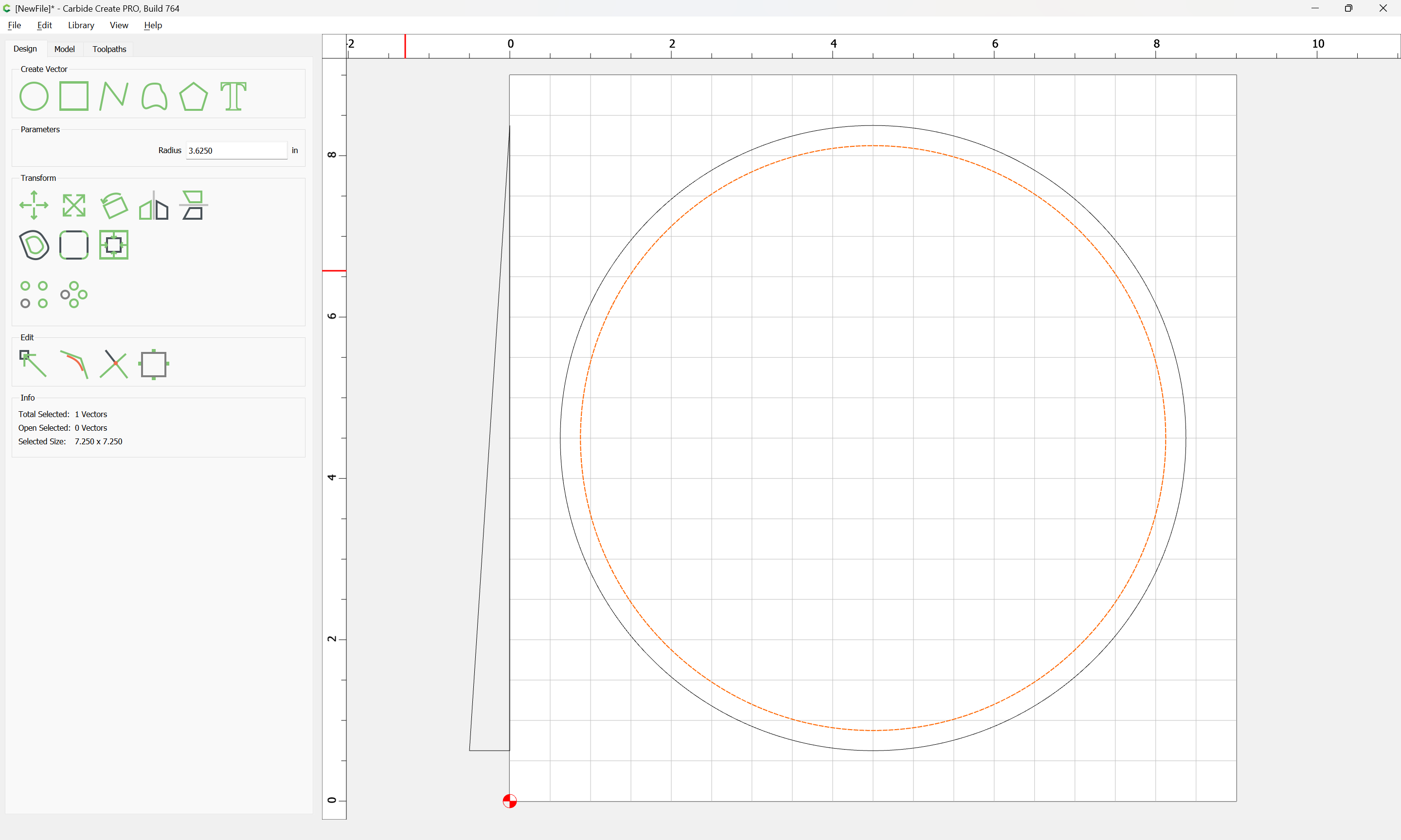
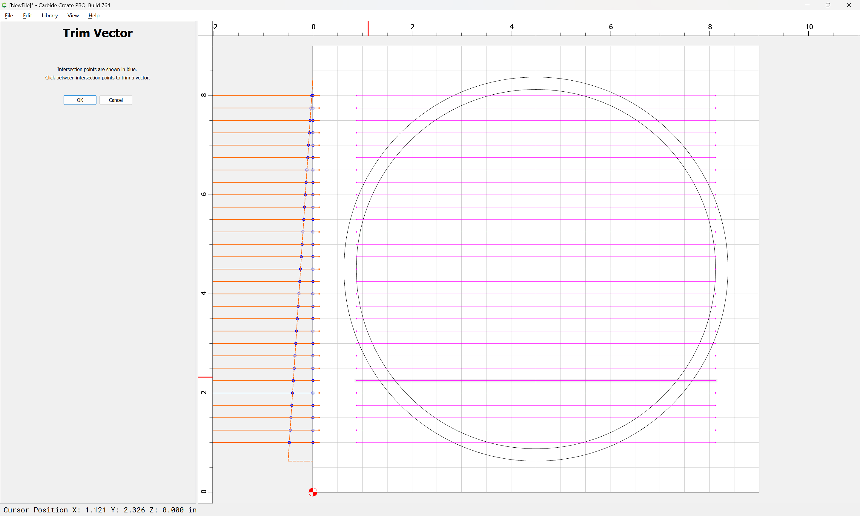
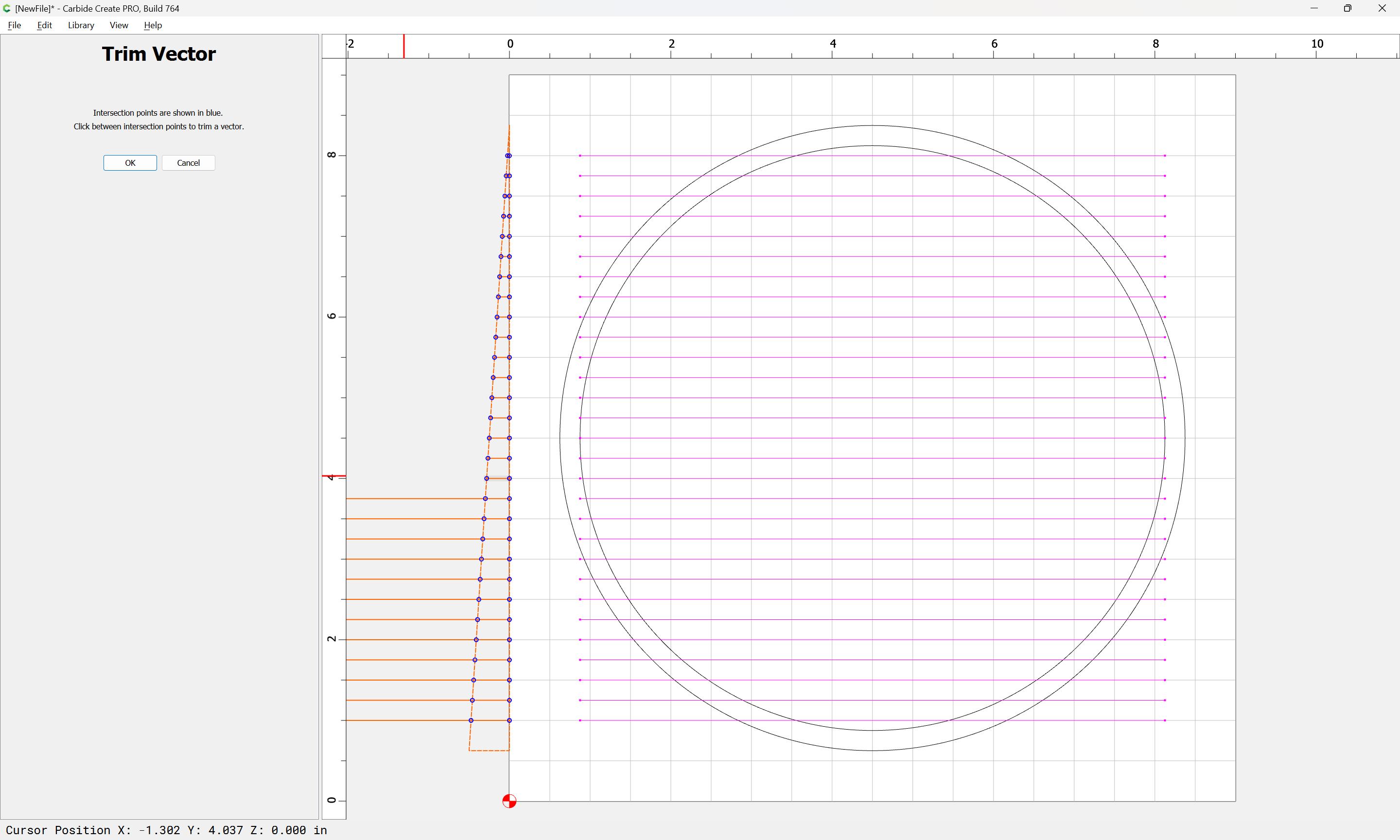
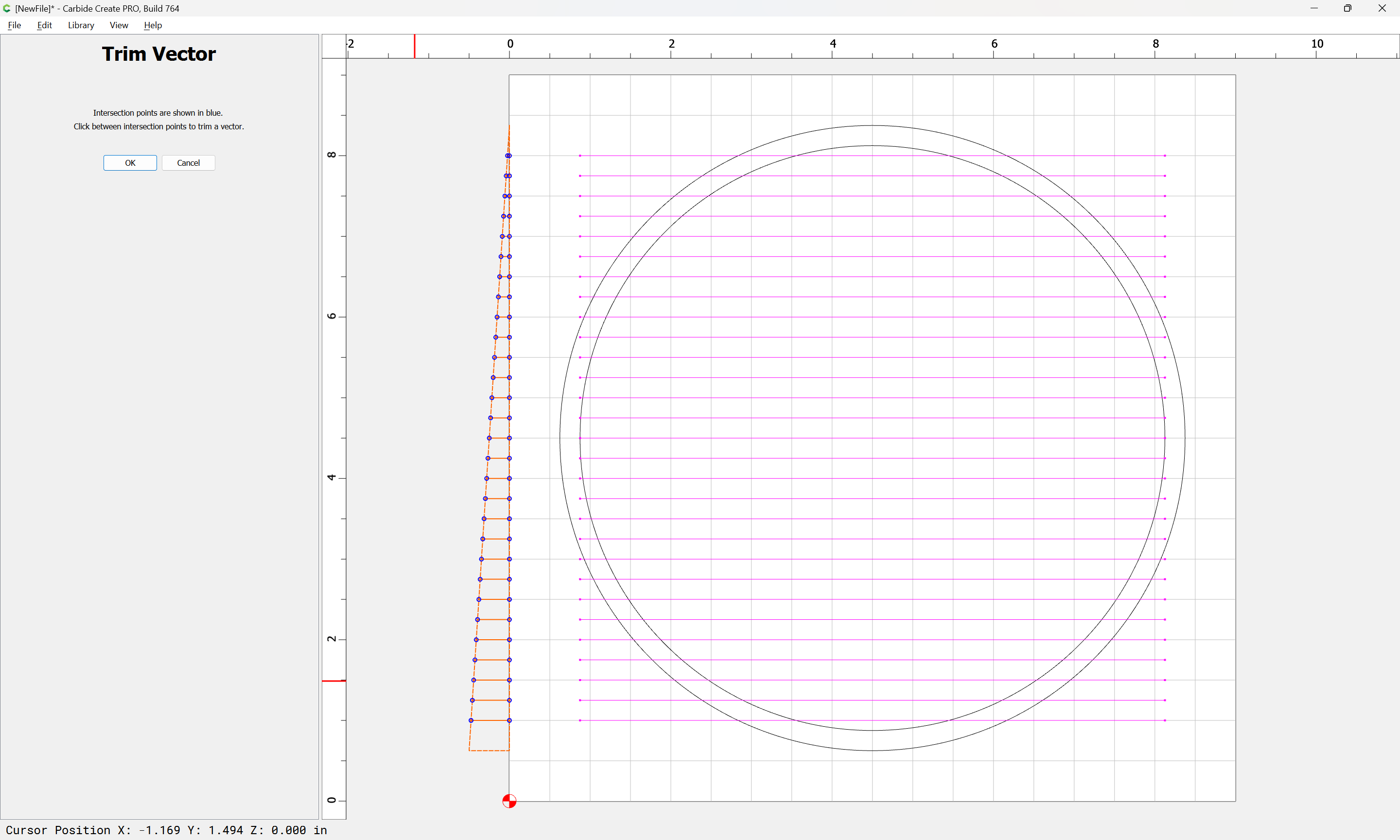
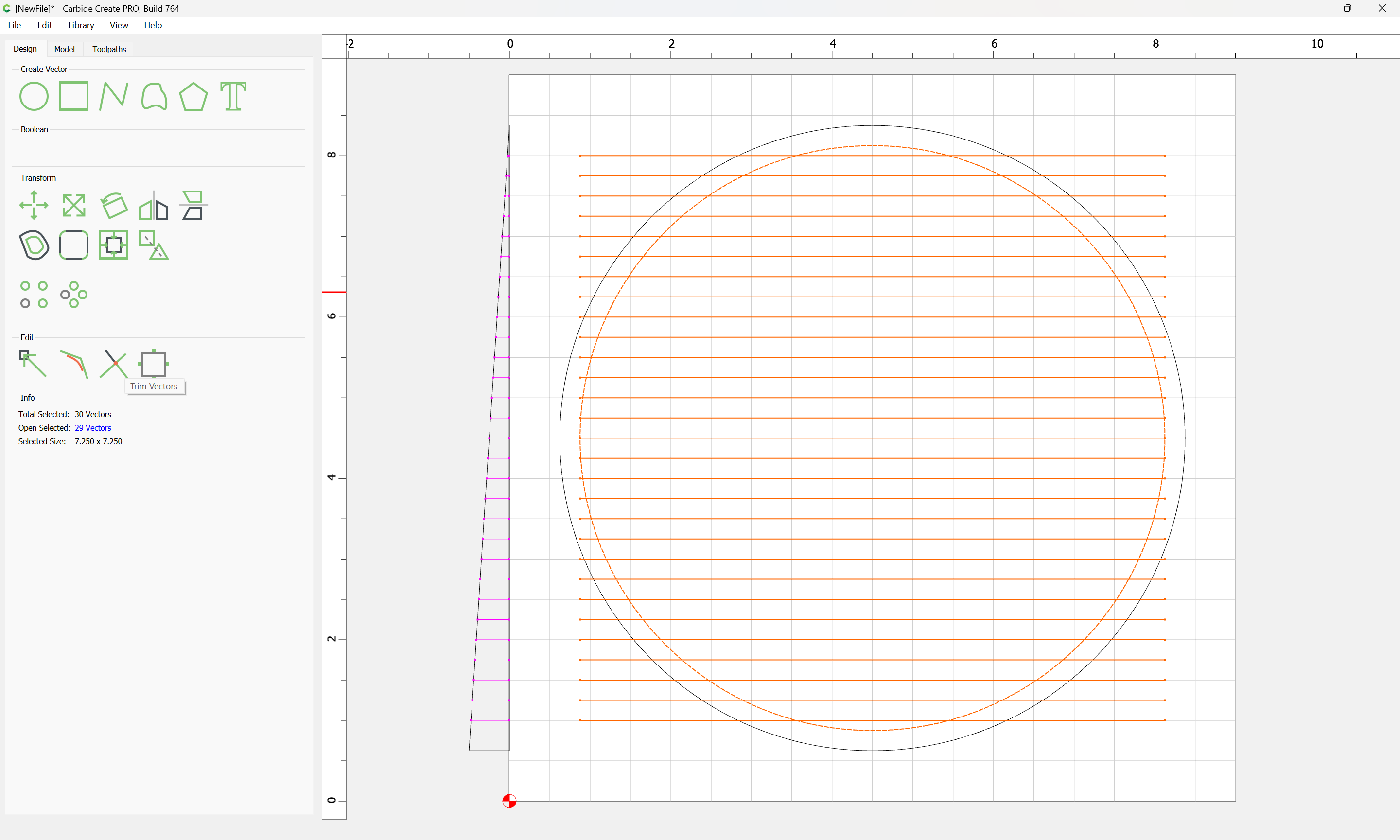
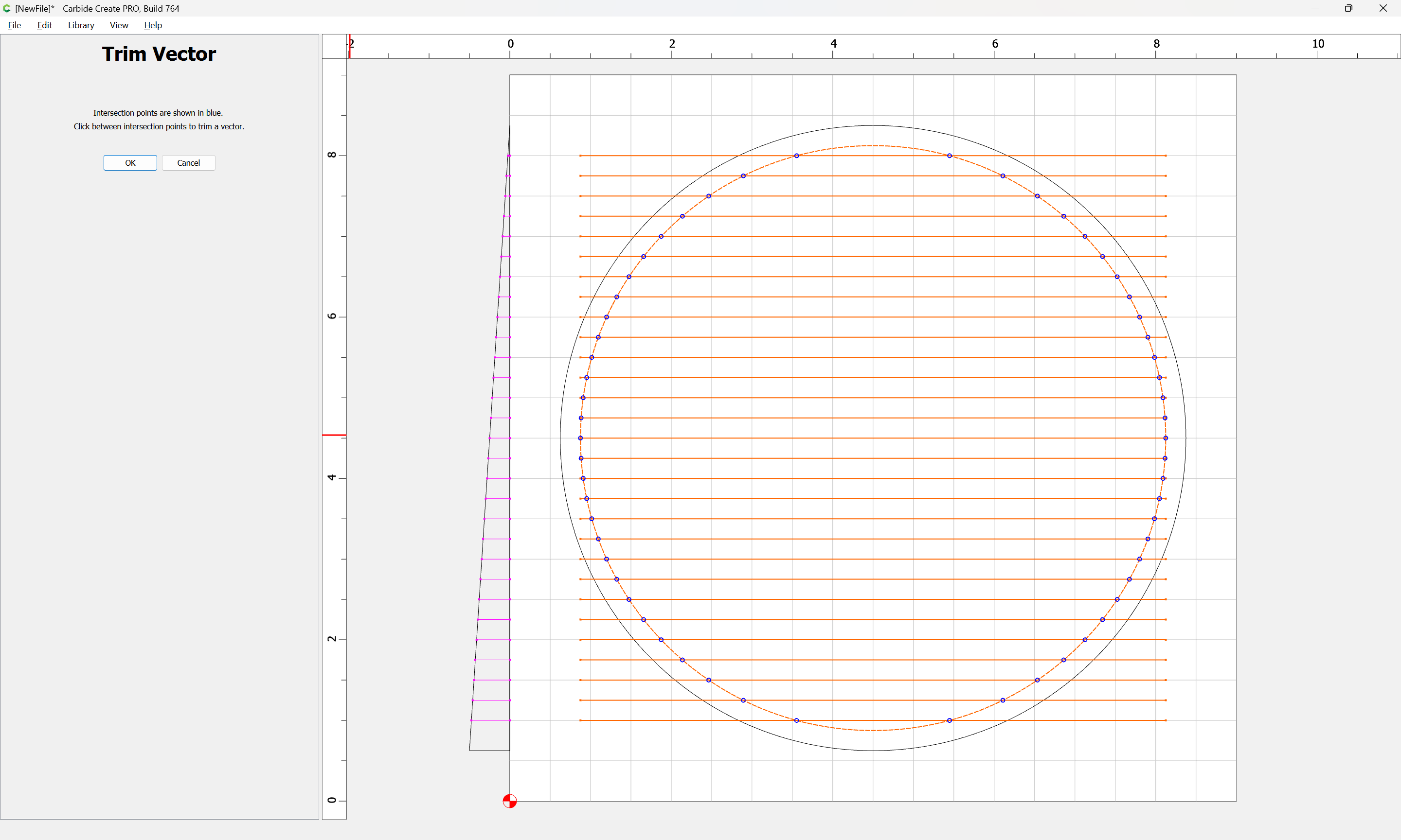
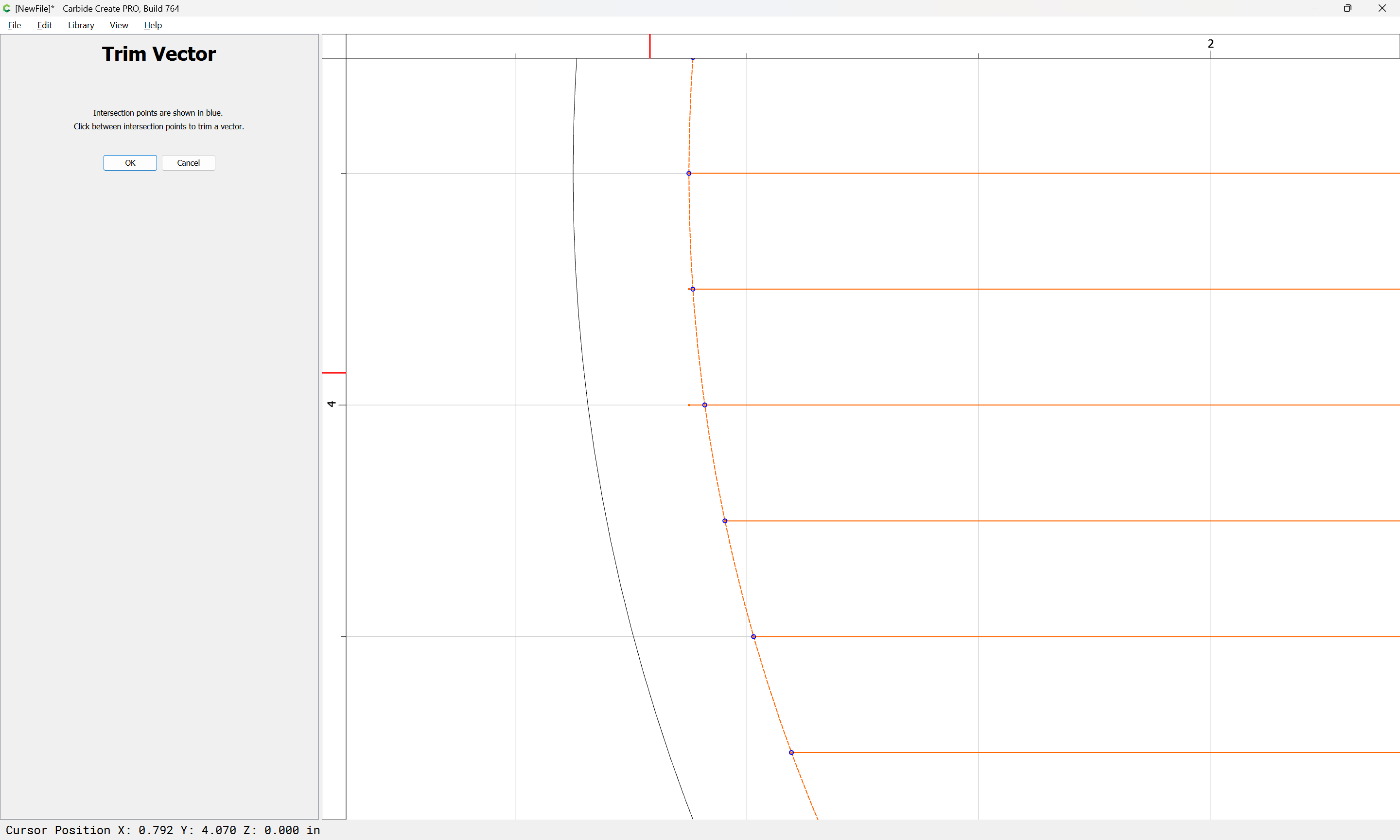
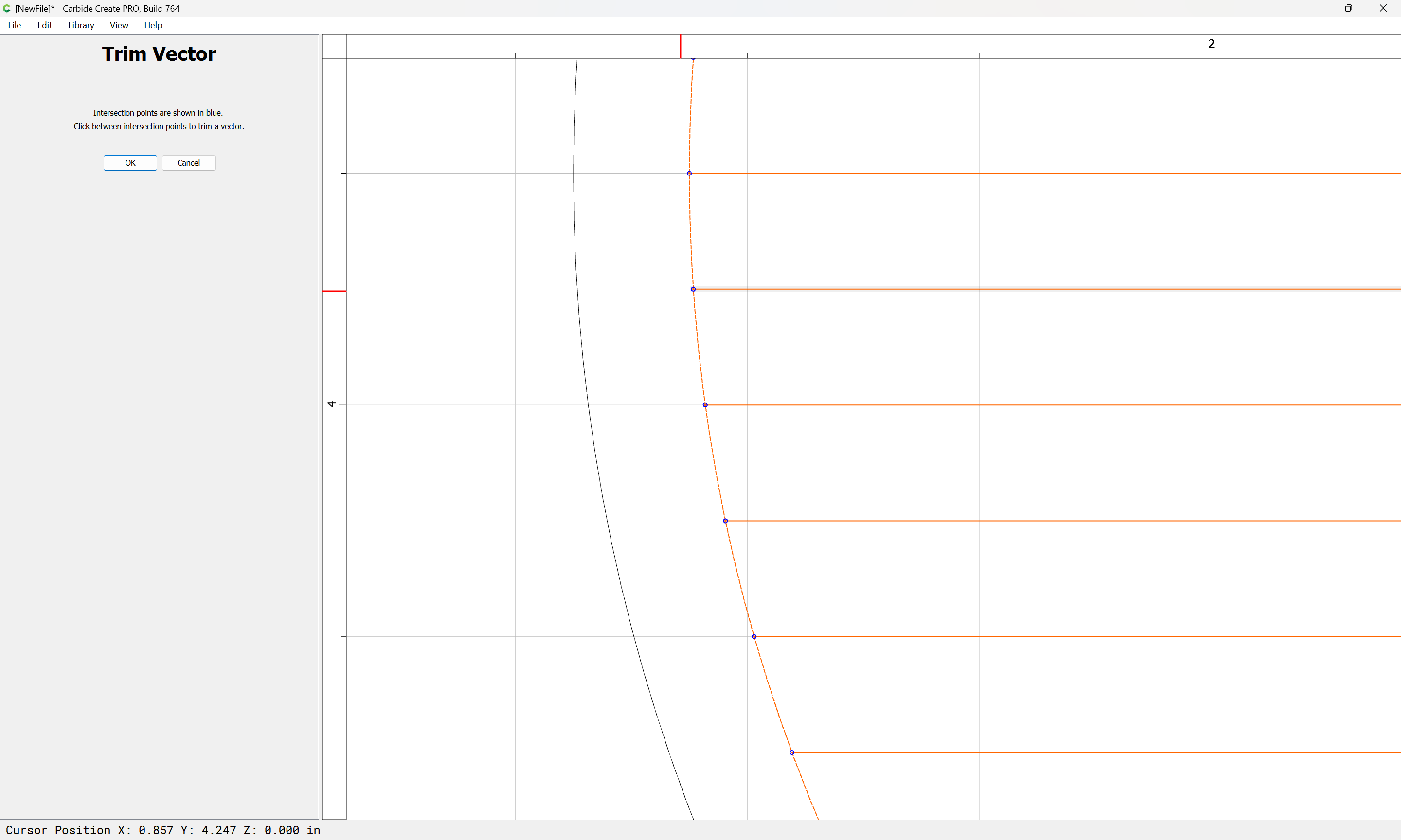
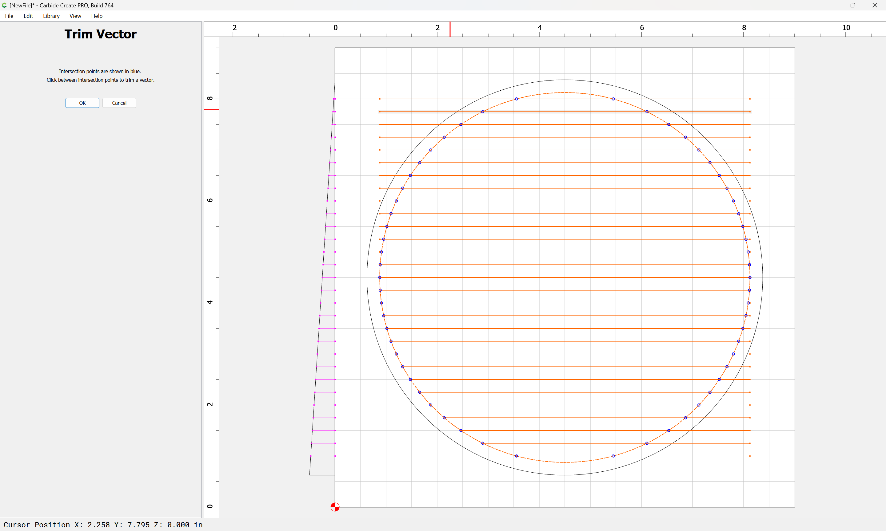
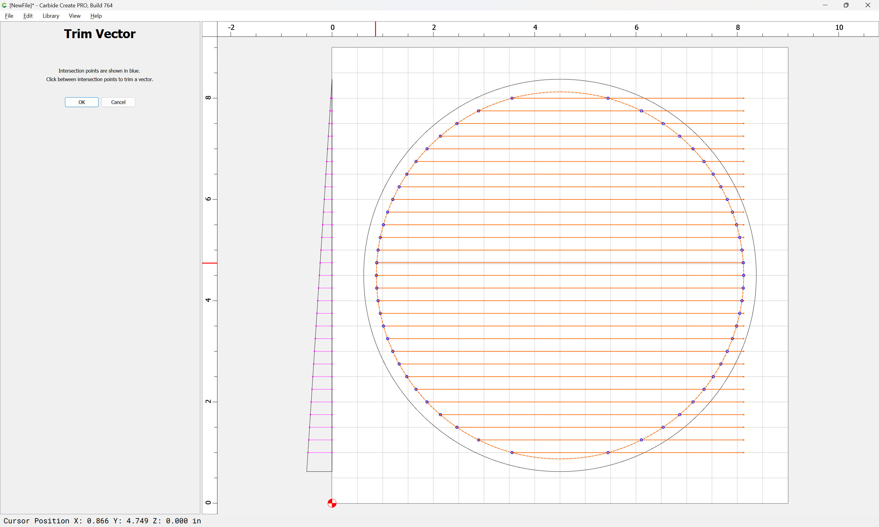
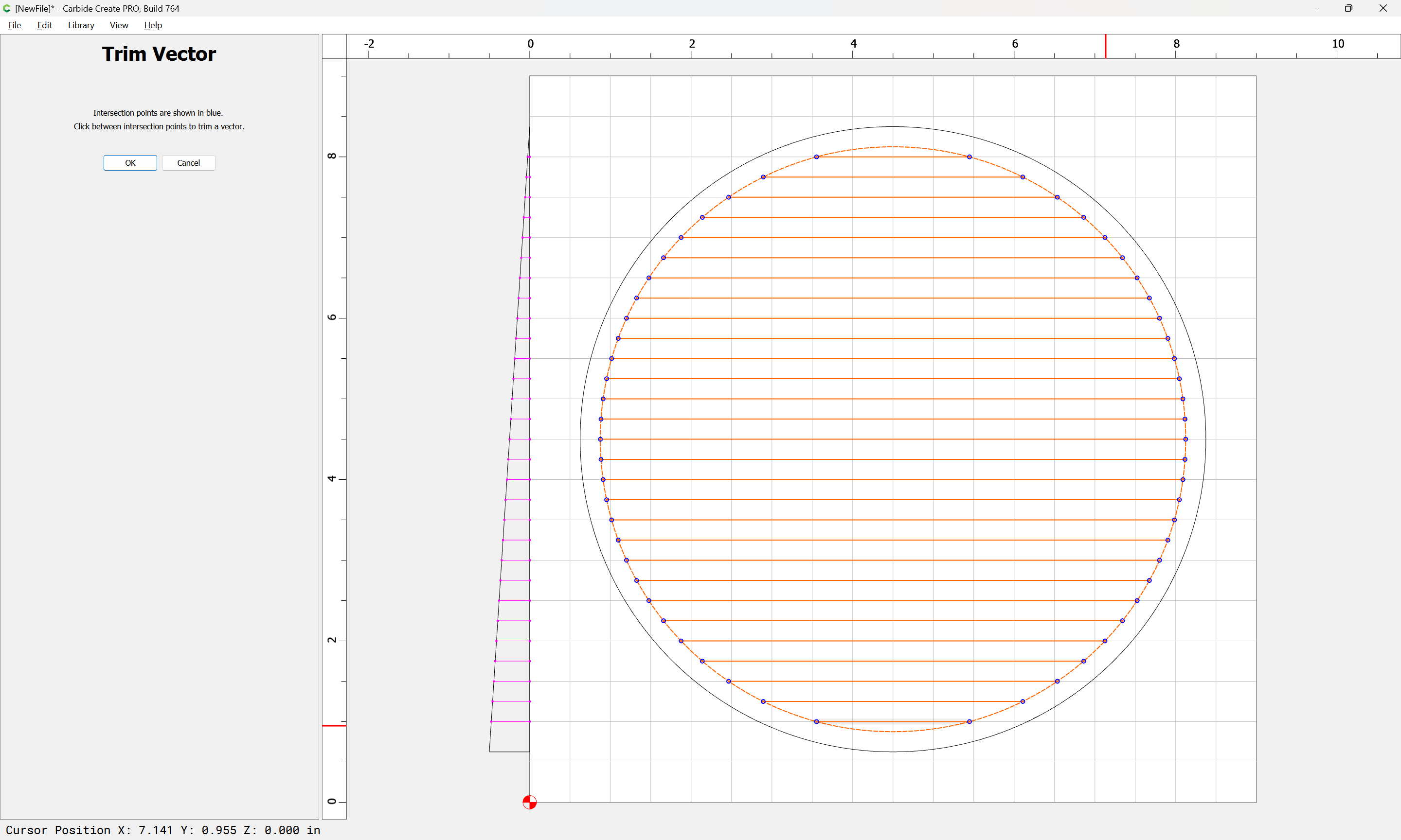
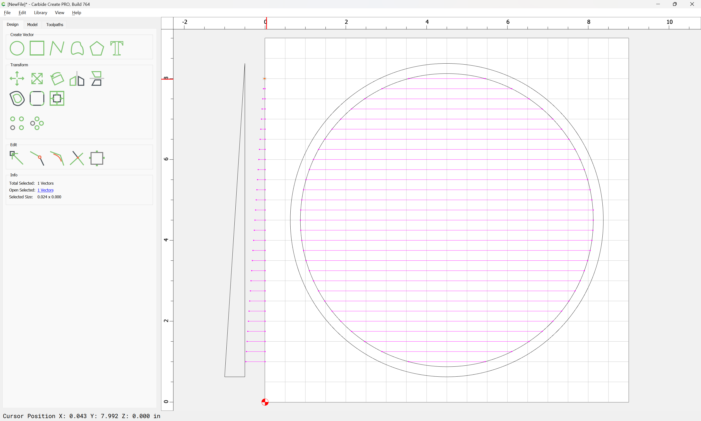
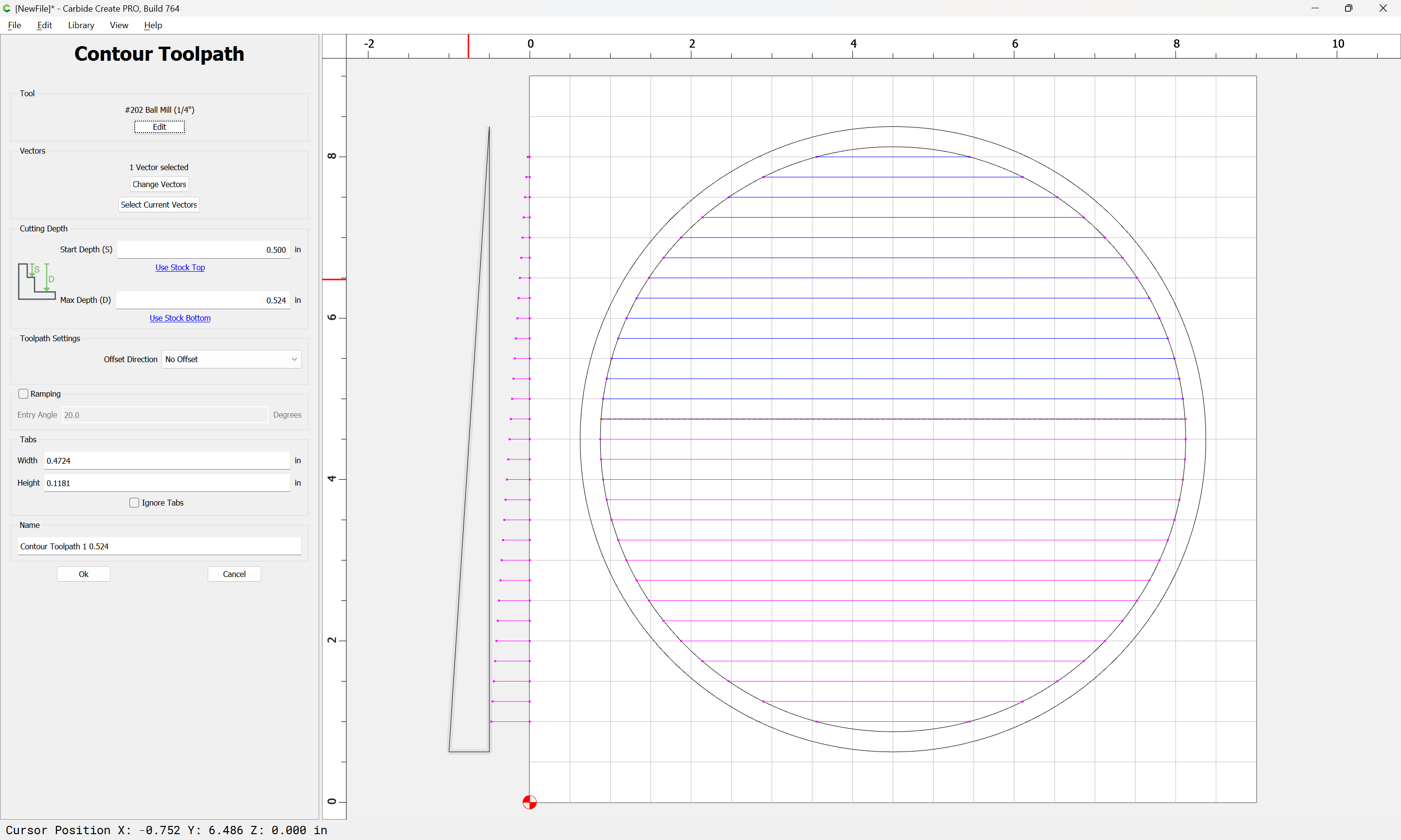
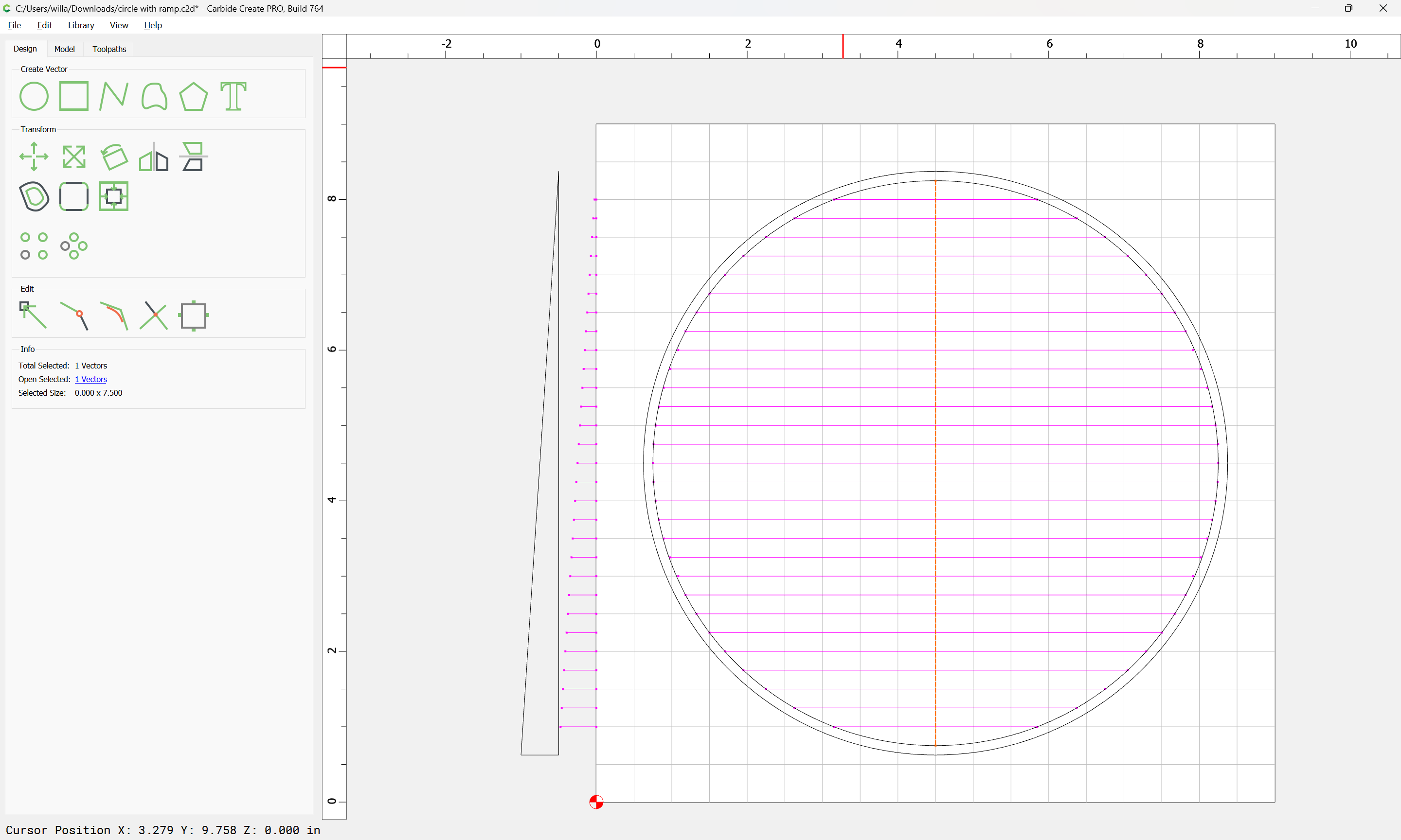
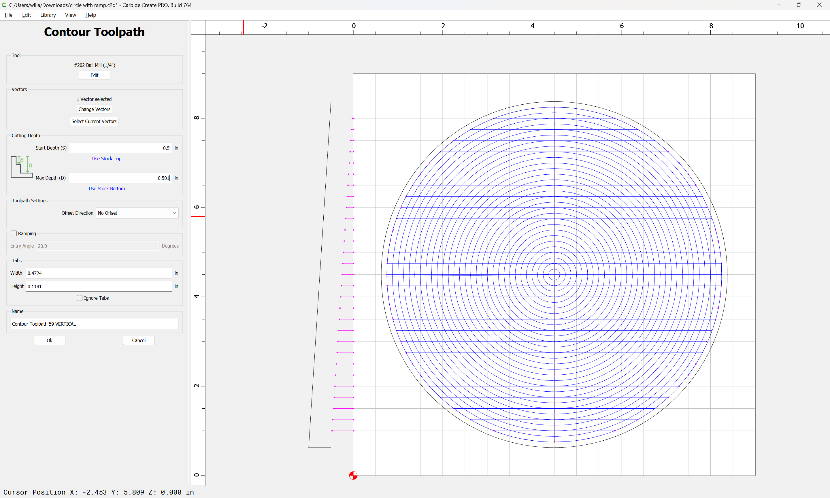
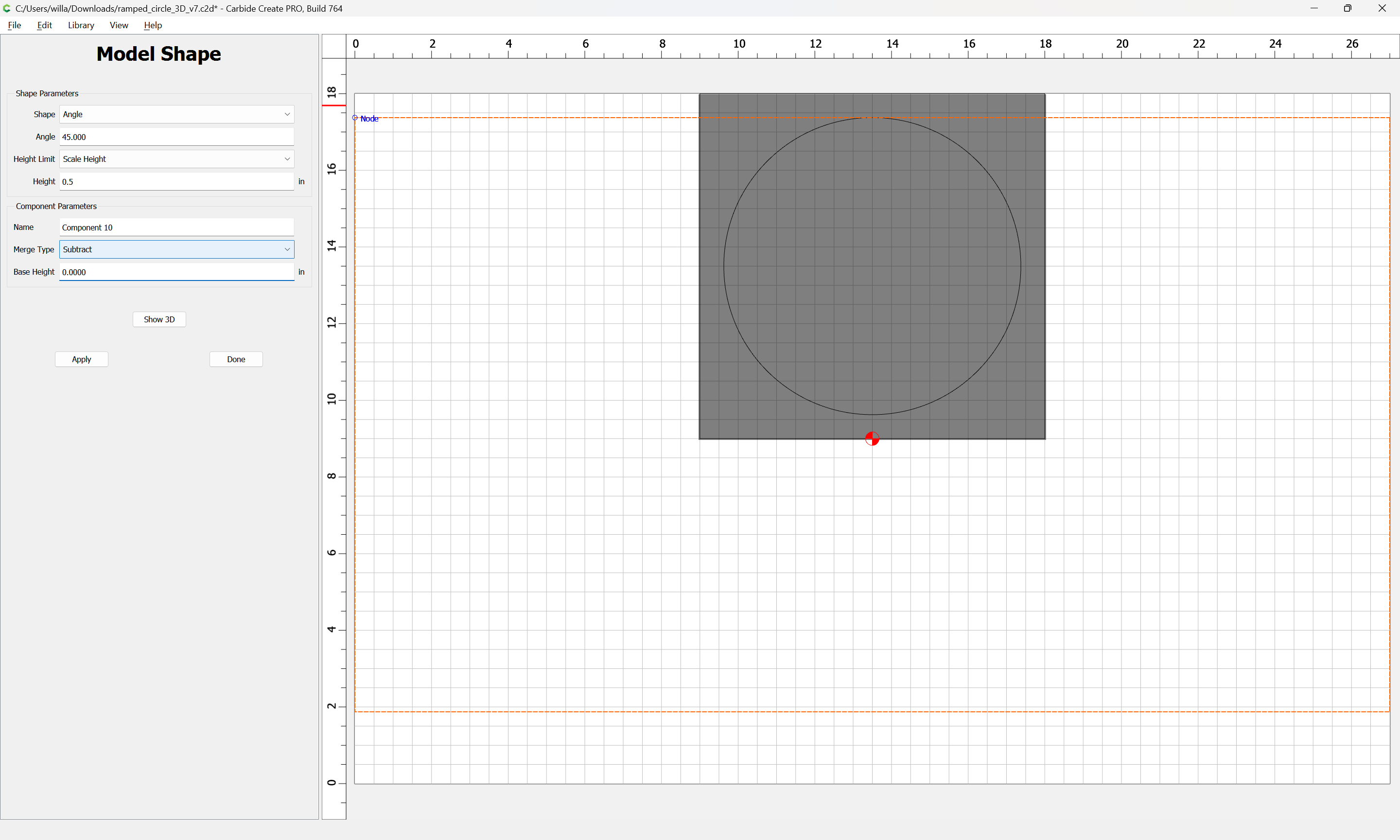
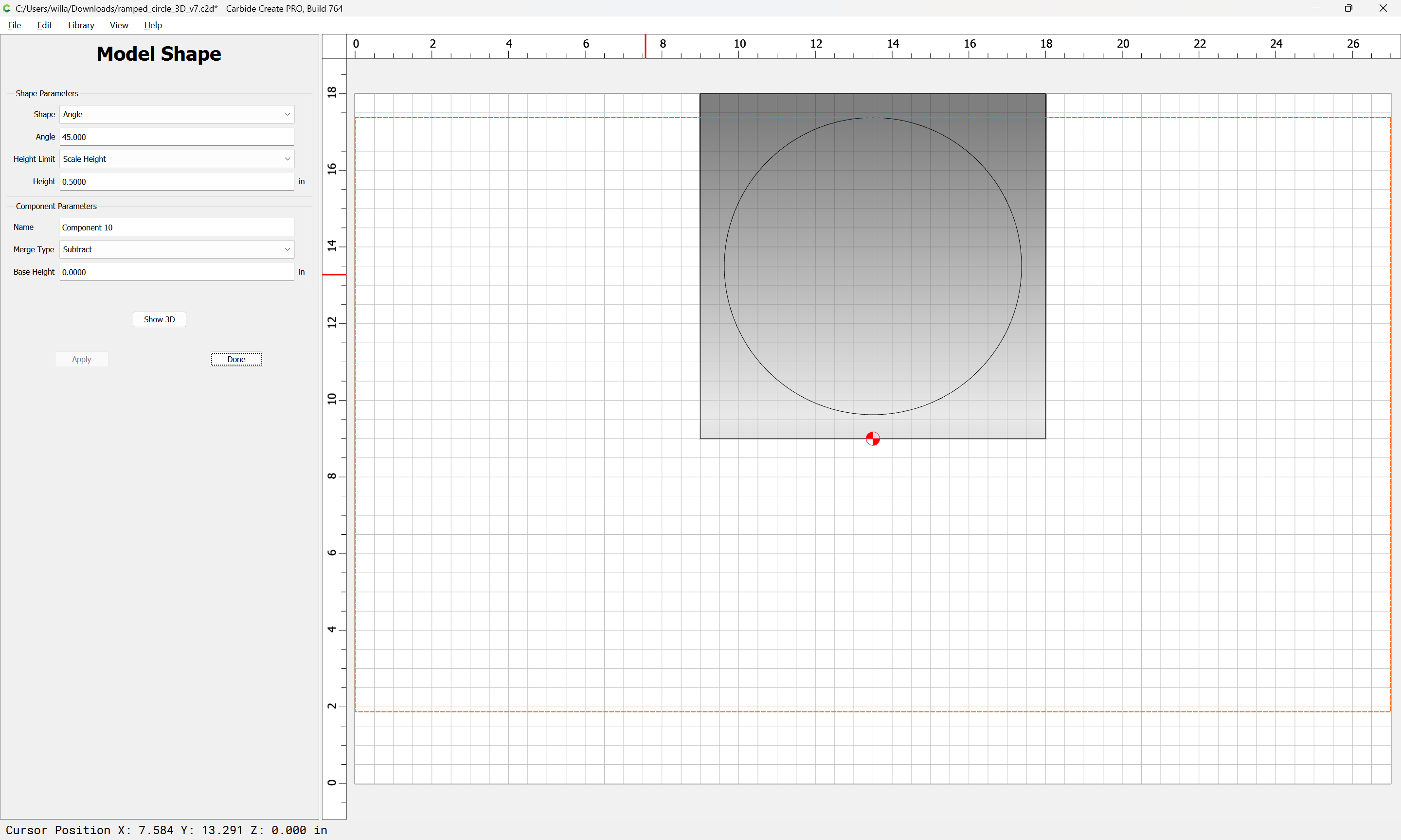
Unfortunately that’s not what I’m trying to accomplish with this next-to-final step. I’ve got about 90% of the detailed carving that’s to be done within the circle. Essentially I want to do now is create a Contour circular cut, at the perimeter, with approximately a 0.5" front-to-back slope. I anticipate using a Point Roundover or V bit for that, probably stopping when the bit Shoulder is about .25" an inch from the surface at the front. After that I anticipate doing the normal cutout routine using a regular 1/4" bit.

Your help is greatly appreciated as I wend my way through another learning experience.

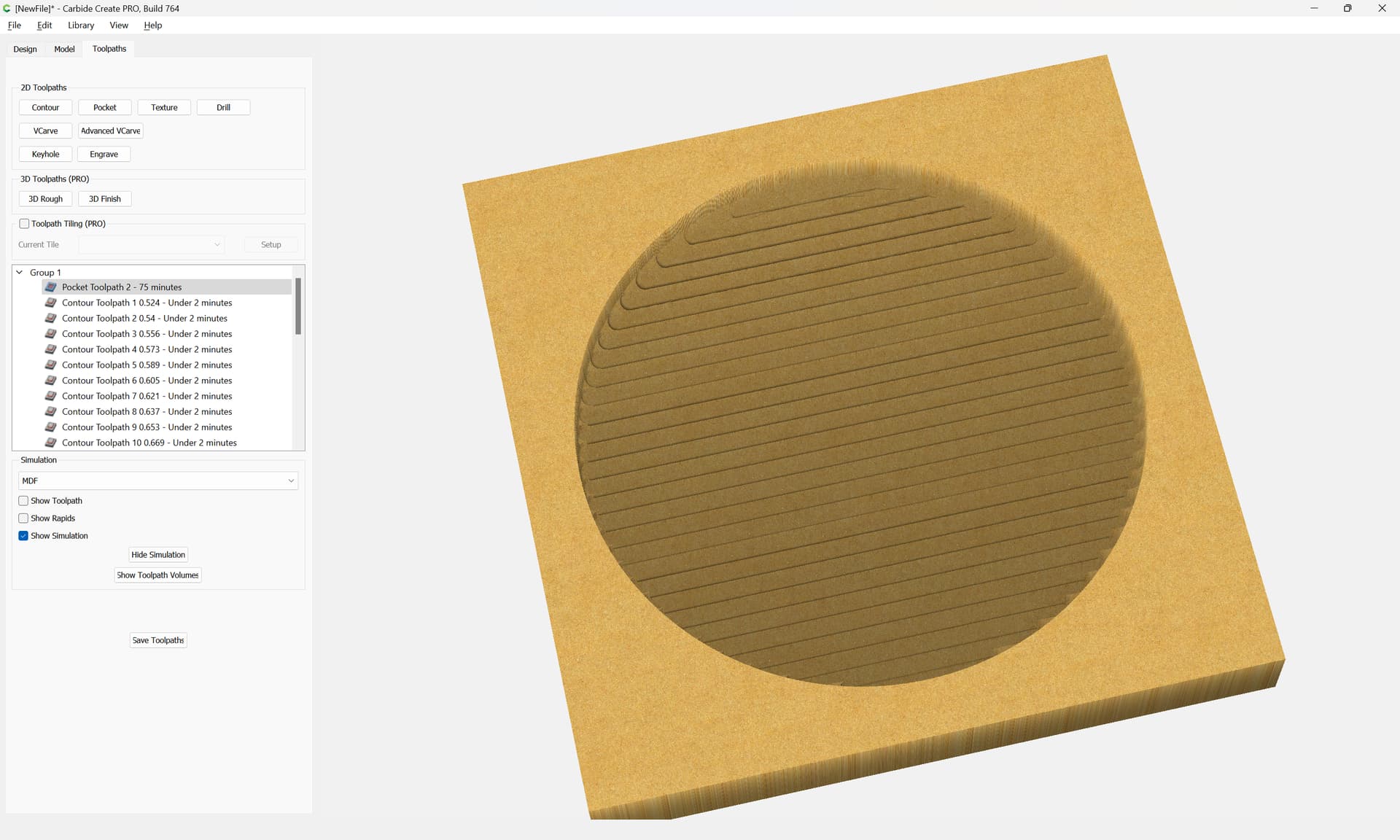
Carbide Create isn’t able to do a V carving on a 3D surface — you would need to model the design you have into the 3D model, then cut the entire 3D model.

What about the point roundover? I know the simulation doesn’t recognize it but I’ve come up with workaround calling it an End Mill and running it along around a curvy edge line. I just have to take into consideration that the point isn’t really a point and compensate for that.

Carbide Create cannot apply toolpaths other than 3D toolpaths to 3D geometry.

For roundover tooling see:

Tod (with one “d”):

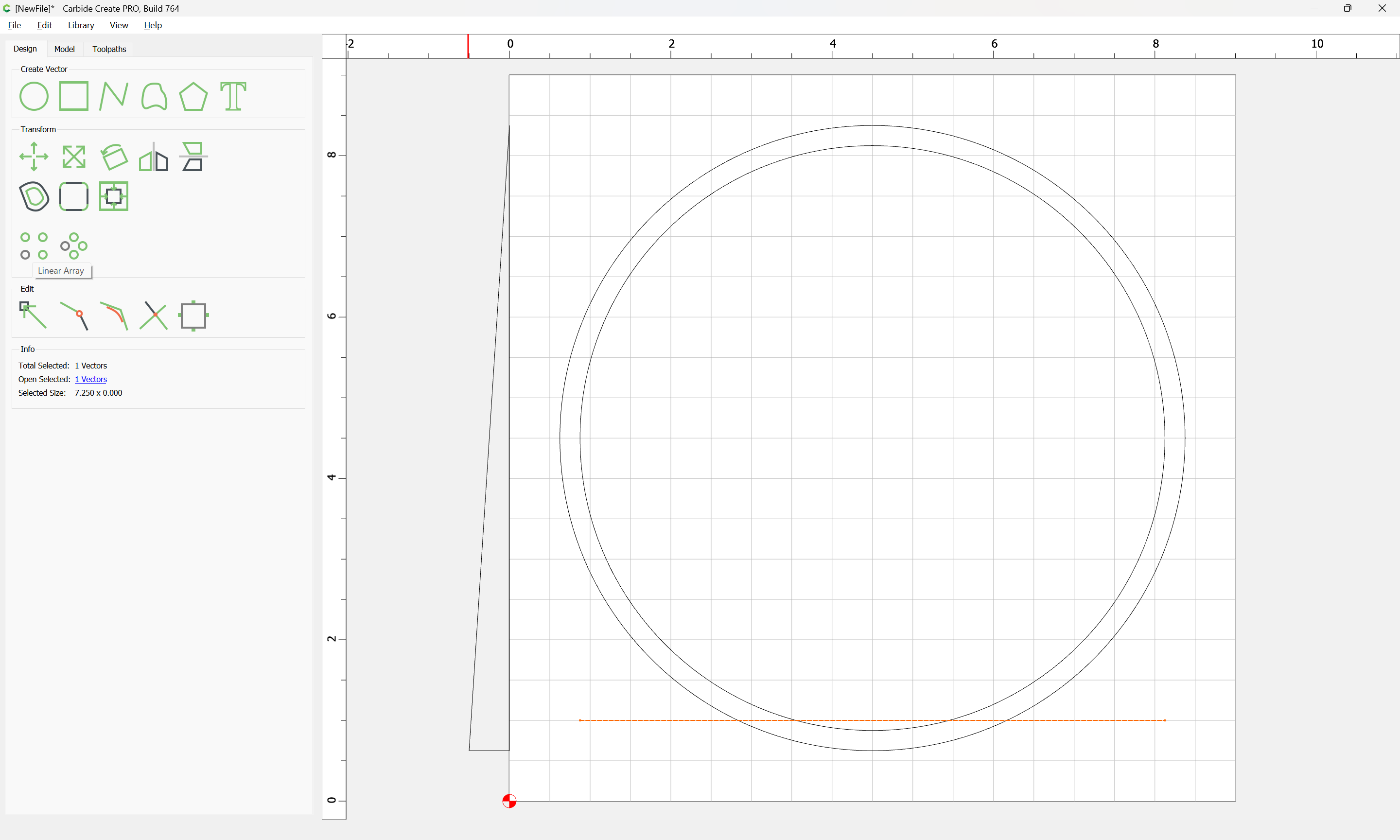
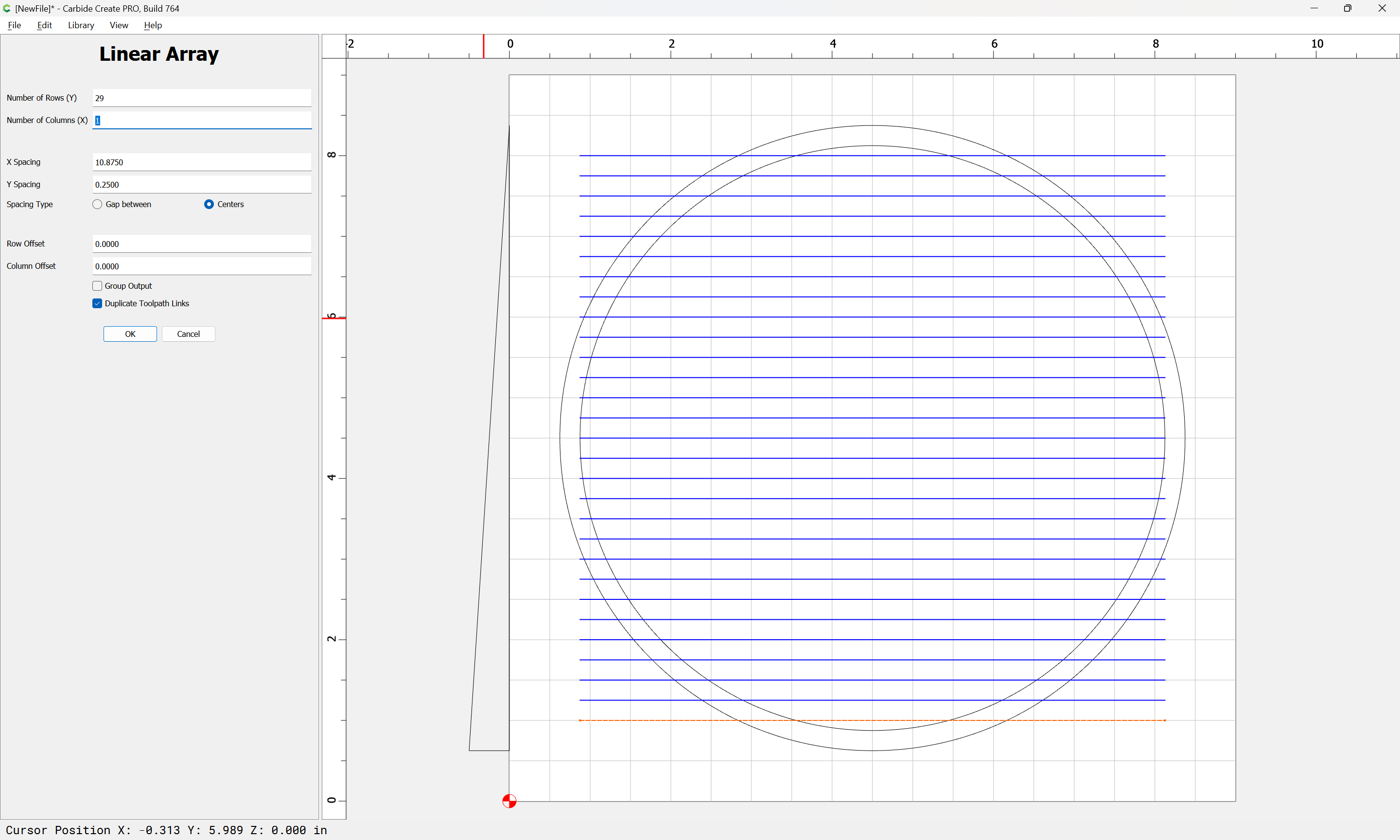
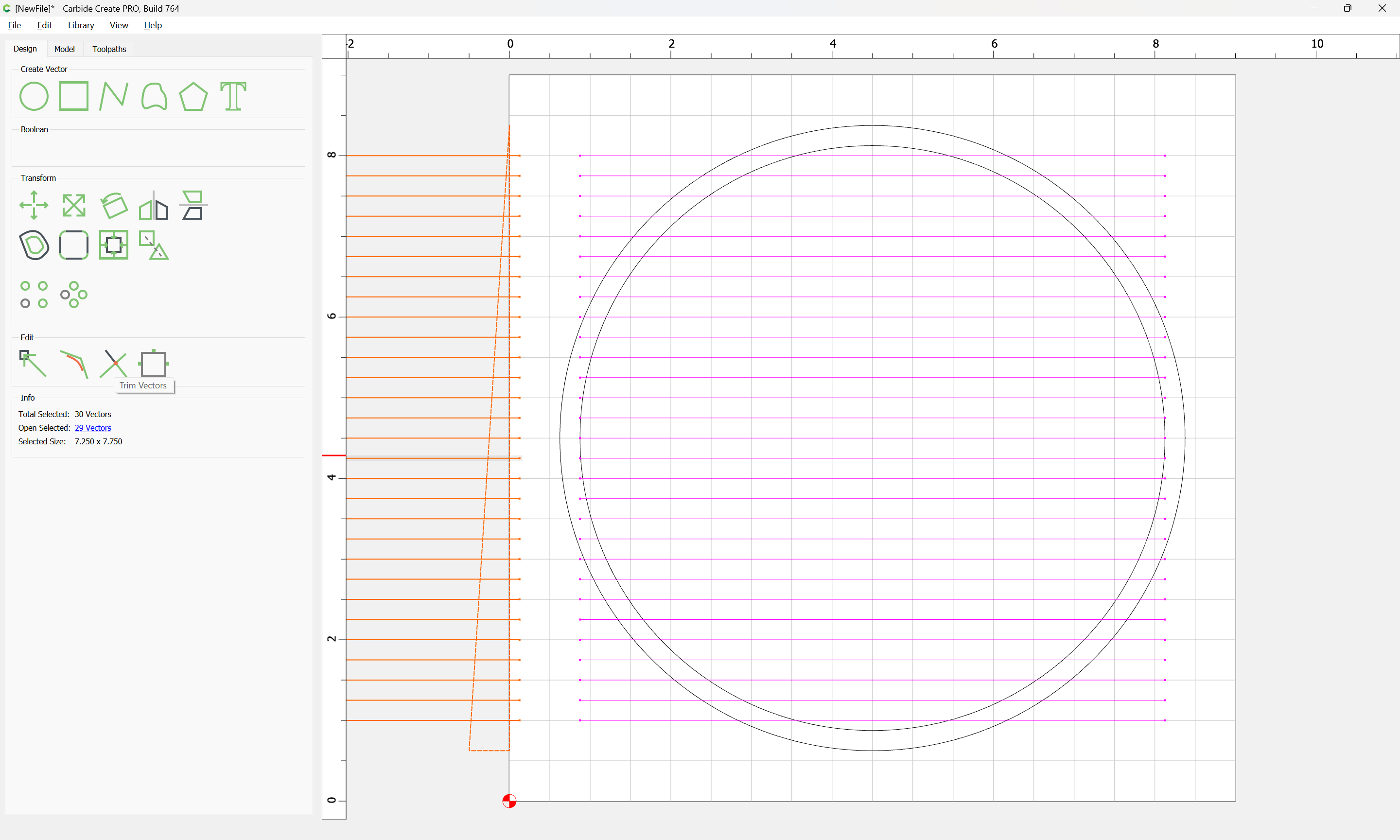
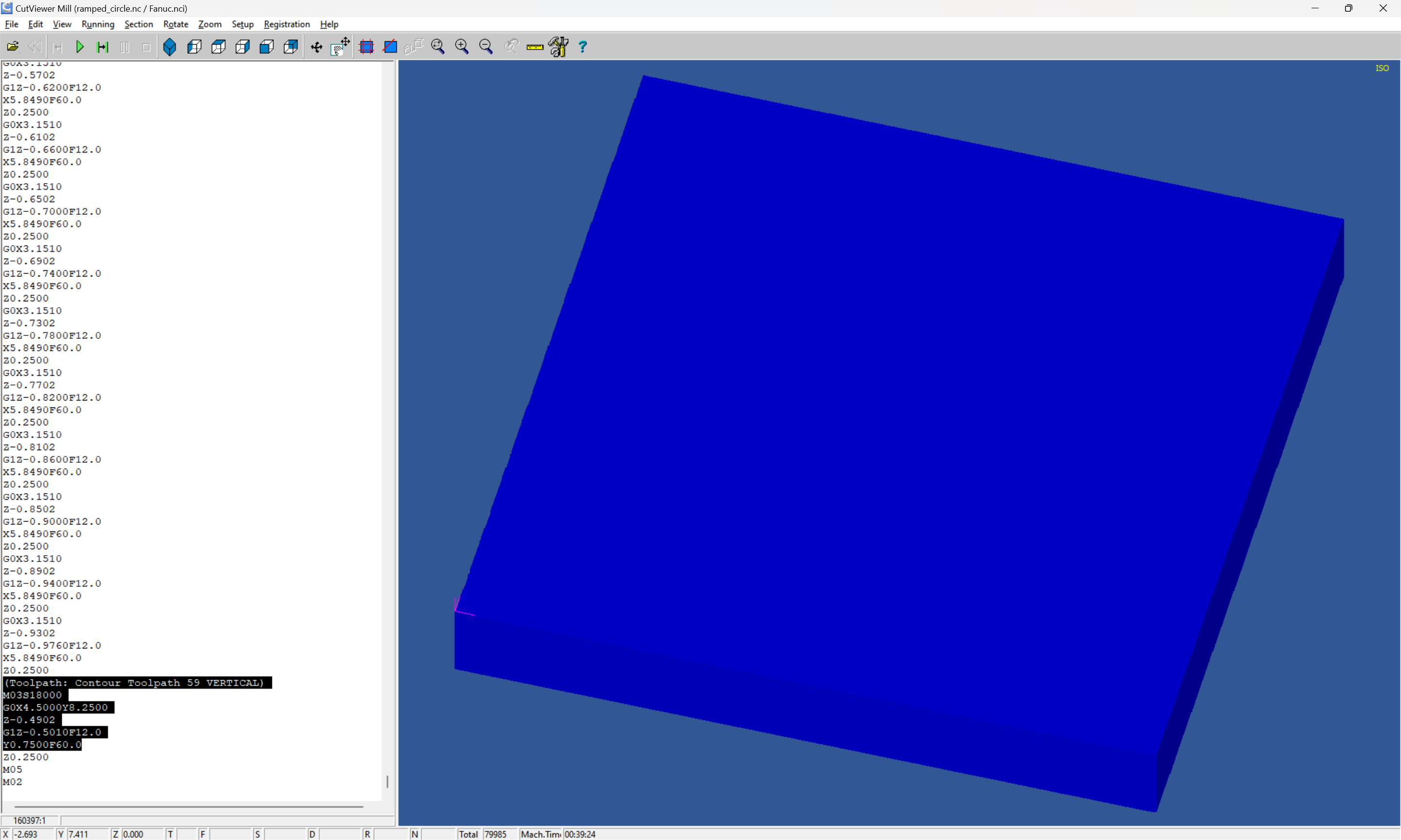
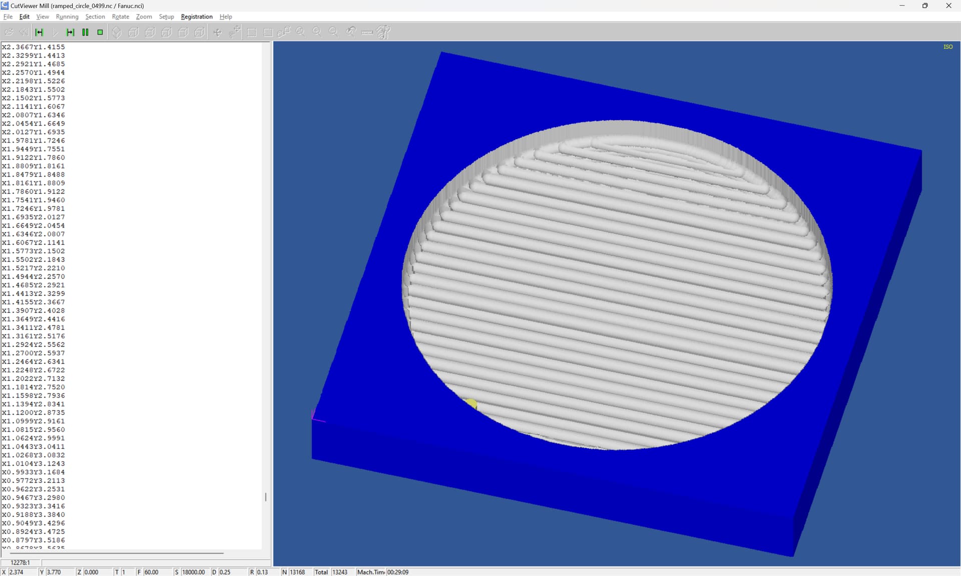
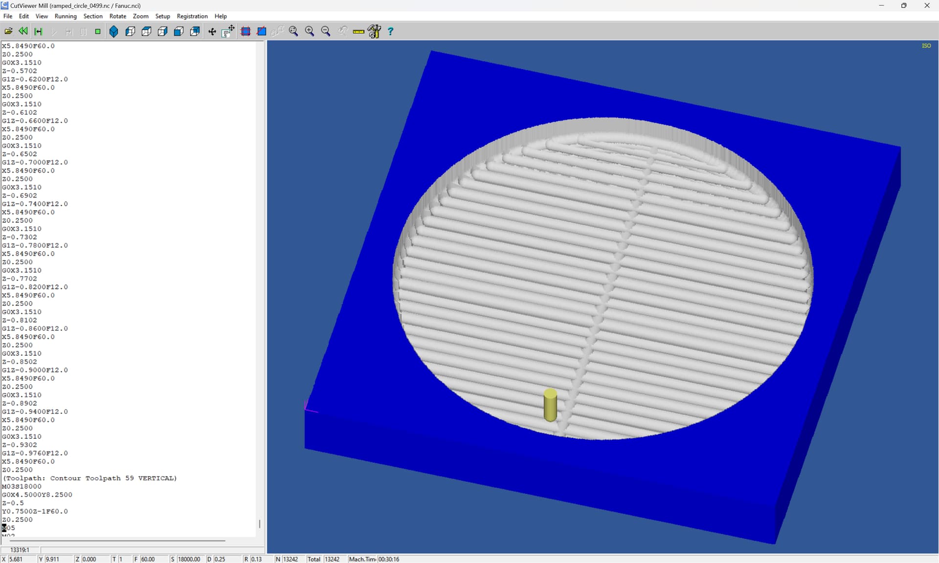
It took me a while, but I think I’ve figured out how to use what you posted. I ran it through CAMotics to really get a basic clue. Then figured out that since I’ll most likely be be doing the cutting with a 3/32" Point Roundover I need to do the cutting incrementally. About .03" per pass. Excel to the rescue. Starting with your “Z” numbers, I tweaked away at it and with about 40 passes it will do exactly what I want. My dimensions will probably change along the way, but pretty sure I’ll be able to plug in whatever new numbers I need.

Another step on my learning curve.

Big Thanks

1 Like

This topic was automatically closed 30 days after the last reply. New replies are no longer allowed.