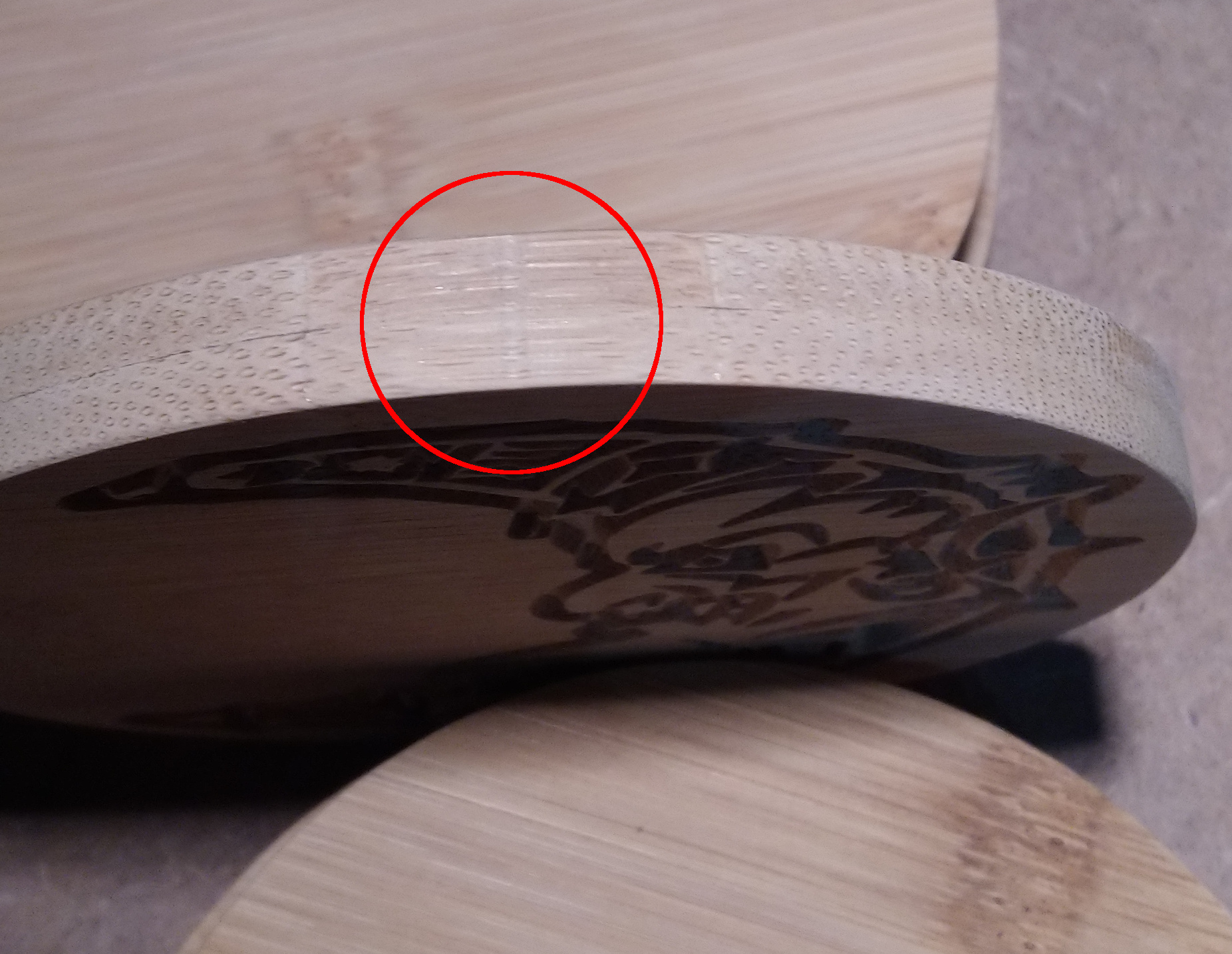
I’m sure this has been asked as thousand times before, yet somehow I cannot find any relevant post, I am probably not using the right keywords. While cutting circles (coasters…), I get this small groove at the point where the endmill starts/end each cutting pass:
Thanks Will. I suspected deflection but thought this was not likely due to using a 1/4" endmill in wood. It’s high time I get over my old habits/lazyness and systematically go for the roughing + finishing passes approach now.
I had issues with the same thing. As will mentioned a finishing pass works wonders here, or adding a long ramp on each cut - 1-2” will generally stop the problem too. I also get grooves when I’ve used tabs, I haven’t worked out how to fix that one, so I just don’t use tabs any more
I’ve seen the same problem many times. The spindle and gantry assembly for the Shapeoko is not particularly rigid. When you’re cutting a workpiece around its perimeter, the spindle has a tendency to deflect away from the workpiece by a small amount as its moving in X-Y motions. When the spindle is plunging, its X-Y position dwells at a fixed point and thus it straightens out and cuts a little deeper into the workpiece resulting in a scalloped cut on the outer edge of the part.
Here’s something that I tried to address the problem: Its probably not the easiest way to cure the issue, but it was very effective. The example below shows the geometry that I created to cut a simple obround part out of MDF.
When programming in Carbide Create, my first step is typically to make a rough-cut by offsetting the outer perimeter of the part by .030" (STEP 1)
Carbide Create always plunges in the lower-left-most part of the selected toolpath. If I were to create the finish-cut toolpath as one single step, then the mill would plunge tangent to the lower-left are of the part and create the scalloped groove that Julien mentioned in the first post. Instead, I revised the outer profile of the workpiece so that it extends outward on the lower-left side of the part (making it look like a cartoon speech bubble with a pointer to the lower-left). This results in the cutter plunging outside of the finished profile of the workpiece.
STEP 2 cuts a portion of the finished profile. The cutter plunges at the pointer of the speech bubble, and then makes a finish-cut completely around the perimeter of the part (except where the pointer is).
STEP 3 finishes off the final outline of the workpiece. The cutter plunges to the lower-left and follows the inside path of the triangle shape, thus milling away the pointer that remained from STEP 2.
The others here have a bunch of good tips, also try reducing the plunge rate - it can be a little tedious/slow, but will generally help this effect a little too.
Thanks for all the inputs, this all makes perfect sense. Will try and report. @Danelectro I really like the idea of ramping into the finish cut as an extra precaution! did you see a noticeable difference compared to just doing a regular finish cut ?
Plunging outside the of the area where the finished edge is to be prevents the scalloped groove issue from occurring. The appearance of the machined edge was consistent all the way around the part. The only drawback is the necessity to do a little more CAD work up front.
Something I haven’t tried yet but will the next time I’m using the machine, is to simply make a second finish pass around the part to see if that might eliminate the scallop. As I mentioned earlier, I believe that the spindle is deflecting away from the part as it follows the tool path, but it cuts a little deeper into the part where it dwells during the plunge. Maybe if the cutter were to make a second pass (nice and slow) around finish-cut toolpath, it would allow for it to remove another .001"-.002", thus making the scallop less apparent.
I take away from all comments that I basically have two options:
just do the classical separate finish pass, which has very low cutter engagement, so even though the deflection would theoretically still exist, it would be much much less than during the roughing pass. No additional CAD required, but not quite as perfect as it can be.
or doing the small additional CAD effort to make a tangential ramp into the finish cut path as you do, which will ensure perfect consistency all around the path. I don’t use CC anymore (VCarve desktop now), but at least for simple geometry it’s easy enough to add this ramping, I’ll definitely try this. Thanks !
Here’s an easy way to control the cutter’s plunge location so that its outside of the part perimeter and you don’t end up with a “dwell groove” on the edge of the part. Rather than letting Carbide Create determine the toolpath based on the part outline, I simply drew the toolpath by offsetting the parts edges to a distance equal to the cutter’s radius. I then extended the start and end points of the toolpath so that the cutter will plunge and retract outside of the part’s finished perimeter.
This is a part that I programmed in Carbide Create this morning. I was using a .250" cutter, so I offset the part perimeter by .125" and extended the intersecting lines of the part’s lower-left corner in order to create the start and end of the toolpath. When programming in CC, the offset direction is set to “No Offset” so that it follows the drawn path:
If you’re programming a circle, offset the outline, draw a couple of tangent lines, and then trim the circle to the lines (then circle geometry will actually become greater than 360°). This way, the cutter drifts into the part at a tangent, circles the part around its entire perimeter and then drifts off at a tangent.