I put this post together in about two hours so its not refined but it will give you the idea. I thought it would be better to post it as a rough overview than to not post anything. Proceed at your own risk. This will certainly void your router warranty and if you make a mistake it could ruin your router control card.
The Dewalt DW611 router that is an option offered by C3D has built in closed loop speed control so its a nice router for the price. It pretty much stays close to the speed you set it to even when under load. It also includes LED lights in the bottom that turn on when the router is on.
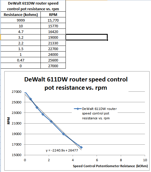
This mod is essentially free other than the cost of a 5k linear pot ( a few $ and the wire needed). It allows you to control your router between 16.000-27,000 rpm. There is a PID feedback controller (mods, feel free to insert link here if you want) called Super PID. It allows you to go down to 5,000 rpm without losing torque as well as use g-code to control the router. I think it costs around $150.
Here’s a plot showing rpm vs. pot resistance setting…
In this post I’ll show you how you can hack the router to provide the following benefits:
- Remote RPM setting. You can set the RPM to a known value. No more 1-6 setting.
- Clean cable management. You can run the router power and control wires through the SO3 cable tracks instead of having them floating around above the machine.
- Independent remote light control. You can have the light on when the router is off which makes zeroing and bit changes easier.
- Remote power control. No more reaching to turn the router on.
What you will need:
- Soldering iron, solder, flux, wire strippers, etc… and some level of soldering skills. I’m not great and it worked for me.
- Heat shrink tubing (various sizes)
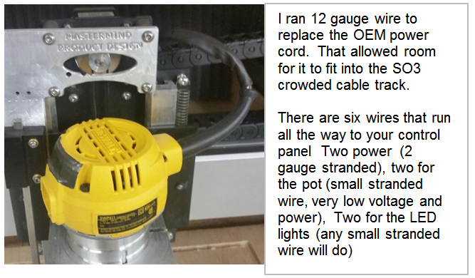
- (for the SO3 XXL) 28’ of 12 gage stranded wire for power wire extension, 56’ of small gage stranded wire for the LED light and Potentiometer extensions.
- 1 5,000 ohm linear potentiometer. http://www.amazon.com/OHM-Linear-Taper-Rotary-Potentiometer/dp/B00X73YUE4?ie=UTF8&psc=1&redirect=true&ref_=oh_aui_detailpage_o03_s00 or equivalent
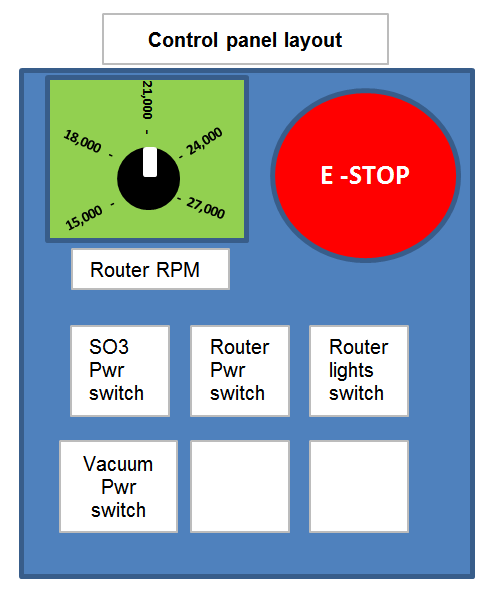
I’m working on my control panel now but here’s what I plan to have in the end…
Here’s what the final install looks like…
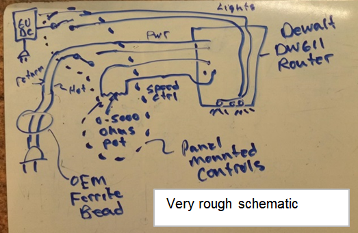
This is a very rough schematic to show how its wired now…
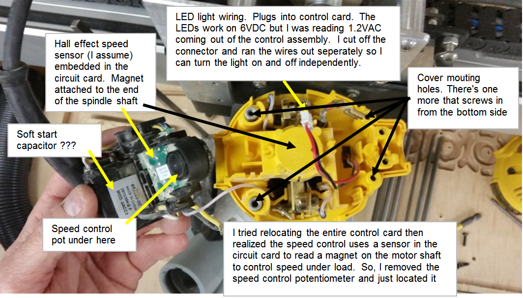
The router has an integrated hall sensor that reads a magnet on the end of the motor shaft. This is used for closed loop feedback so the system can add power under load to maintain the rpm setting. This is a great feature.
You may ask why I didn’t just use a router speed controller. That’s much easier… A router speed controller will adjust speed remotely but because of the way it controls speed you lose torque as you lower the speed so as the load increases the router rpm drops off significantly. This isn’t good when you are trying to maintain cut quality.
*Make sure the router is unplugged before you start!
STEP1: remove the DW611 from the SO3 mount.
STEP2: remove the 4 star head screws from the top and one from under the top
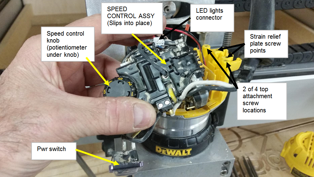
Pull the top off carefully to reveal the following…
You don’t have to cut the OEM power cord but I replaced it with my own wiring so I could fit it all into the cable tracks. The OEM cord is too fat to fit into the tracks. Its not good practice to run 120VAC in the same track as low voltage wiring because a short could cause what you think is a low voltage line to become high voltage. It can also cause EMI issues. I’ve jogged my machine with the router running and didn’t see any EMI issues.
This picture shows the underside of the control card and more wiring.
STEP3: Remove the OEM speed control potentiometer. You might want to watch a YouTube video about how to desolder components. Its not hard but knowing a few little tricks will make it less frustrating with less chance of overheating other components on the control board.
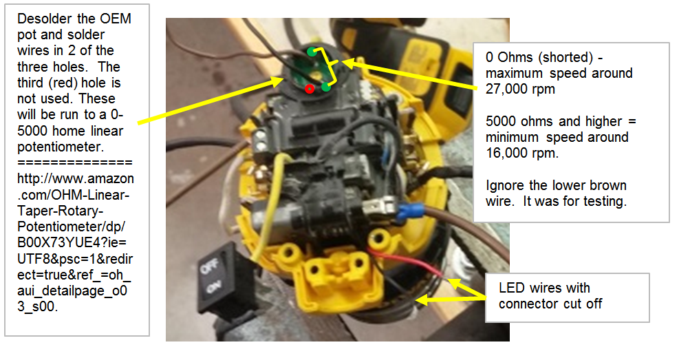
STEP4: Solder small gage stranded wires into the two holes shown. The third leg of the pot was unused so you don’t need to do anything with it.
STEP 5: I removed the router switch but really its fine to leave it in place. Just leave it turned on. If you choose to cut the power cord cut it close tot he control board so you can run the new wires through the strain relief. Cut the connector off of the red and black LED wires and solder small gage stranded wire onto them. Make sure you note which one is positive and which is negative. The red is positive. I’m not sure but it may blow out the LED’s if you connect them with reverse polarity.
STEP 6: Run all six wires (2 power, 2 pot, 2 light) through the strain relief. It wouldn’t be a bad idea to put heat shrink tubing over them also. There’s a metal tab that holds the wires in place. Depending on your wire size you may have to grind out the channel for the wires to accommodate the larger wire bundle. I had to do that. If you want to go by the book you would run the low voltage LED and pot wires out of a separate hole and not place the 120VAC power wires in the cable track. I didn’t use “the book” and ran them all together.
STEP 7 (optional): If you have an enclosure you can twist each set of wires using a drill after it exits the enclosure. That makes the wires look much better and they are easier to handle.
STEP 8: Connect your power wires to a power switch. Connect the LED wires to a power switch fed by a 6VDC power supply. The lights were brighter up to 9VDC but I don’t know how high you can go before it shortens their life. Connect your pot wires to a 5,000 ohm linear resistor. I’m going to run mains power to an E-stop which will feed router and SO3 power.
If you think of steps that are missing just let me know and I’ll fill them in as best I can.
I hope someone gets to enjoy this mod with me. Feel free to post comments and your own builds and variations. If you see any issues feel free to post corrections.