SO3: XXL Unboxing

Well, my XXL (full kit) arrived a few hours ago. Since I know some folks are interested in what you actually get, I thought I would document the unboxing process and share it here along with some thoughts and comments. @edwardrford and Carbide 3D support will want to take note, as there WERE some casualties and oddities along the way.

Rather than leaving anything out, I am going to error on the side of being overly verbose with the amount of pictures I’m sharing. Apologies to the TL;DR and Twitter crowd… :slight_smile:

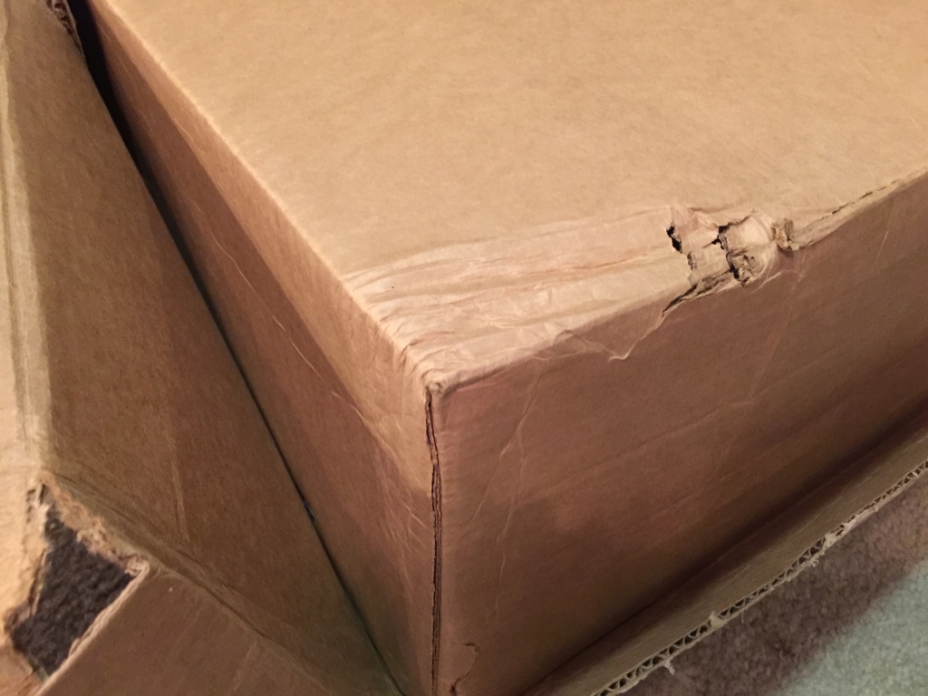
This is the package as it arrived. I placed the Dewalt router on top so you can gauge the relative size of this thing

The XXL is double-boxed, so here is the inner container after peeling off the outer. The box weighs 130 pounds, so there wasn’t really an easy way to slide the inner container out by myself…

As you might have noted in the previous picture, the inner container has moderate damage on this one corner despite the outer shell not showing any indication of such. This is the root cause of the casualties I mentioned and will become obvious in forthcoming shots

Here is what you find once you remove the lid of the inner container…

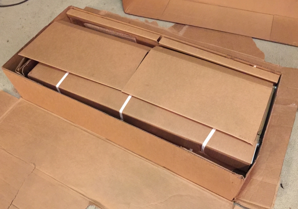
…and after removing some of the packing cardboard…note that two of the sealed boxes are actually empty and used as filler

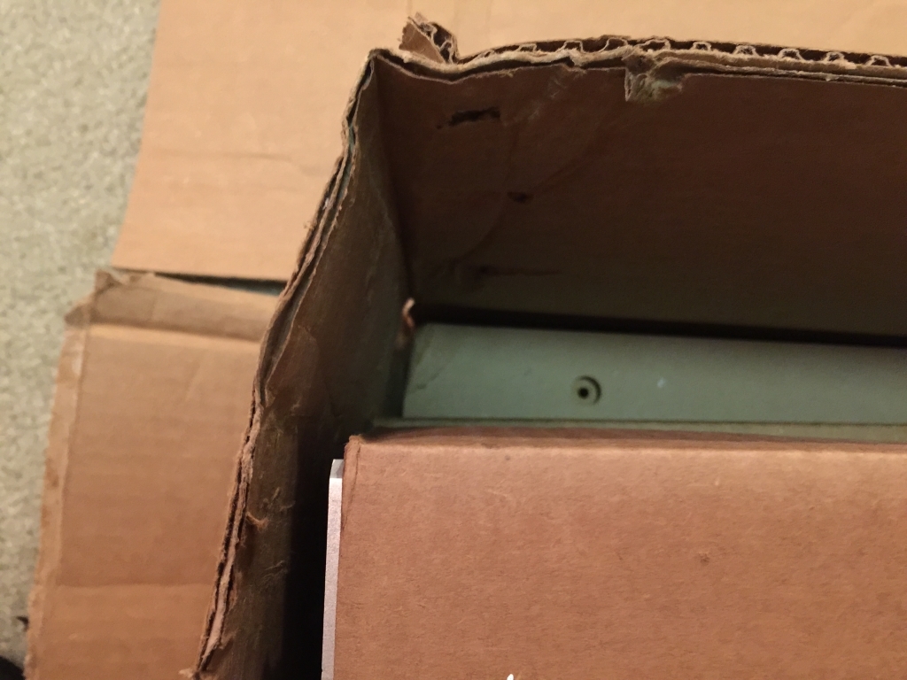
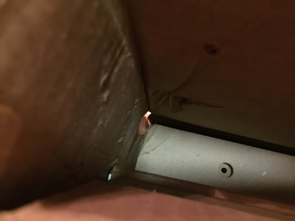
Now, back to the corner damage…let’s take a peek down inside the container to see that things are not all well…

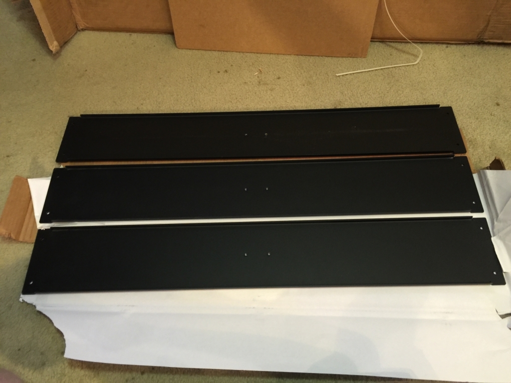
Here’s what the wasteboards looked like removed from the carton - these are 42" x 19.75" each, for the record

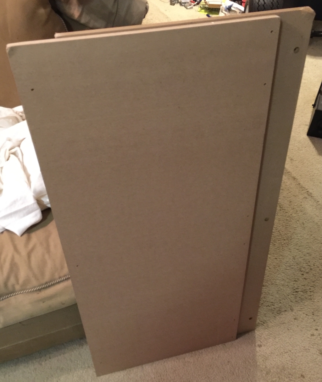
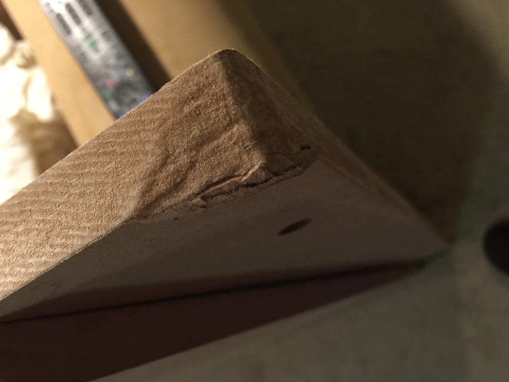
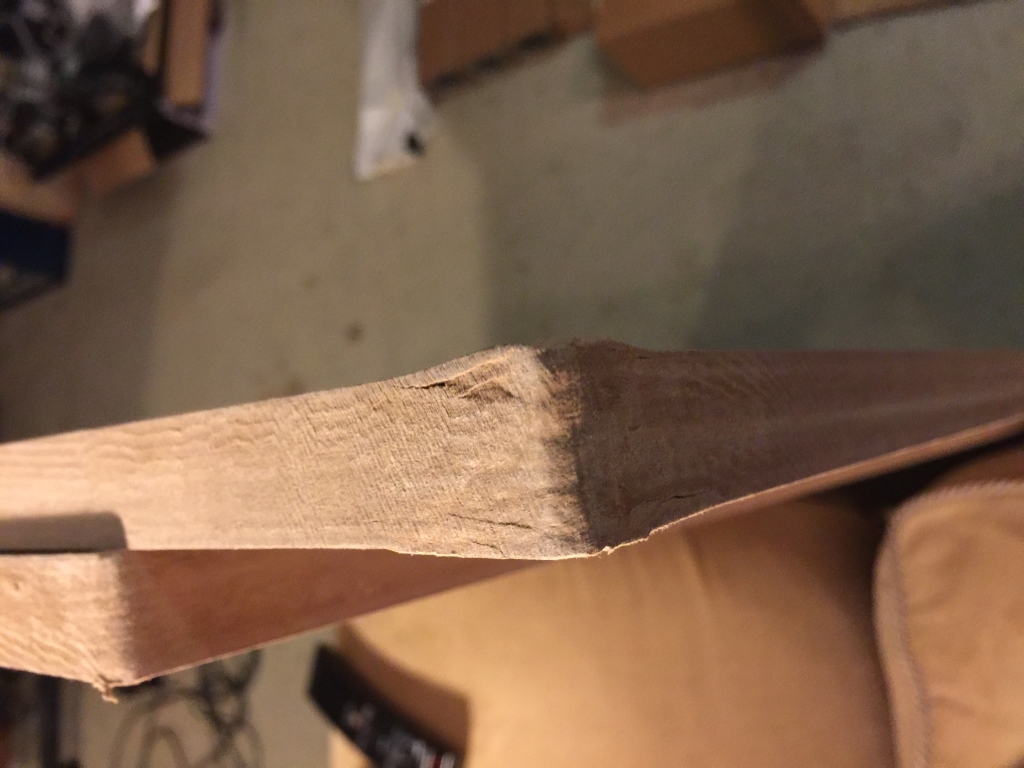
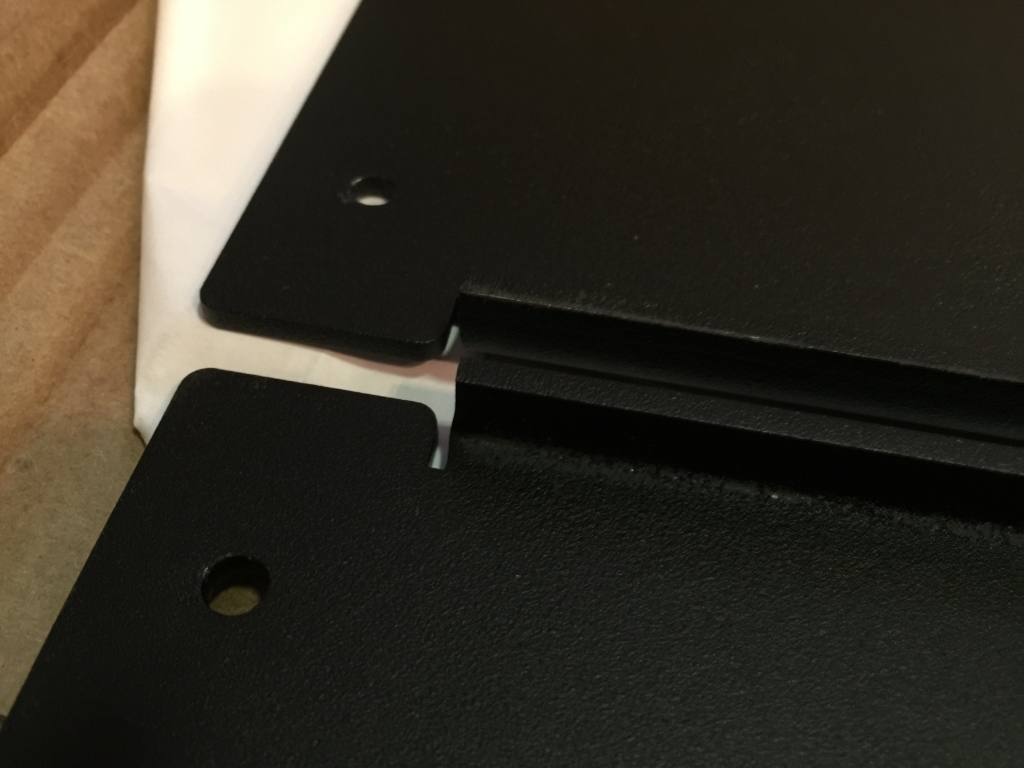
Now some closeups of the corners that were crushed…one wasteboard is worse than the other…I’m not pleased with this, but I don’t know if ultimately the damage will cause any mechanical or precision issues were I to assemble as-is

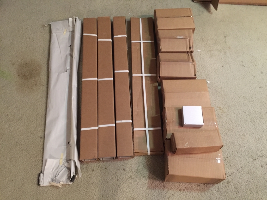
Moving on…I have now removed all the contents of the inner carton. This is everything else (beyond the wasteboards) as packaged

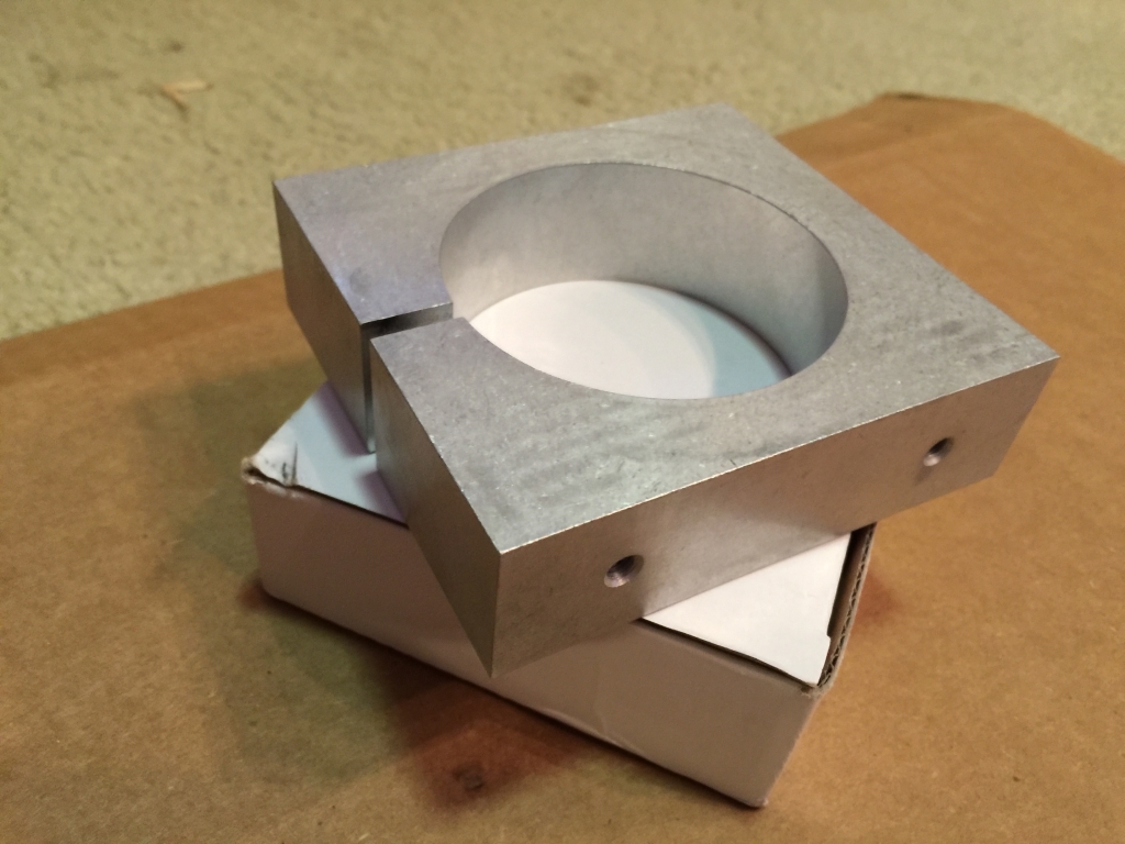
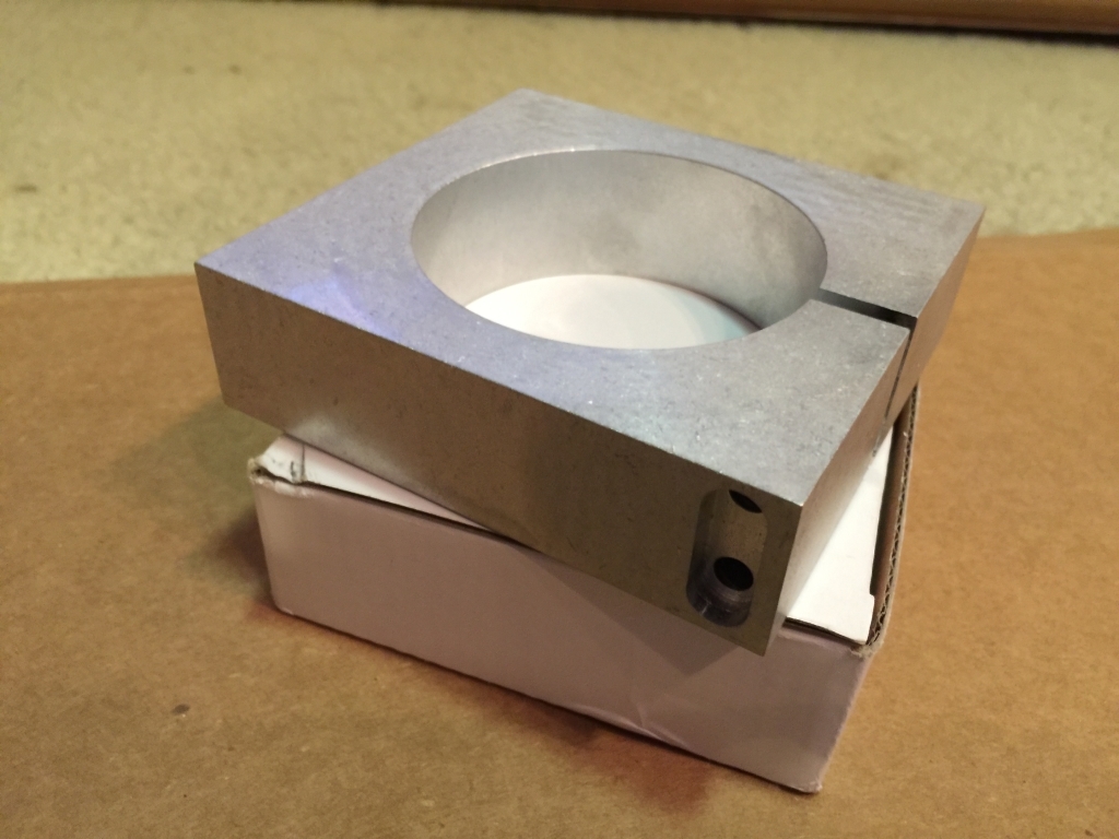
I did not order the kit WITH a router (already have several), but here is the Dewalt 611 spindle mount that is included. SO3 owners will find nothing new here…

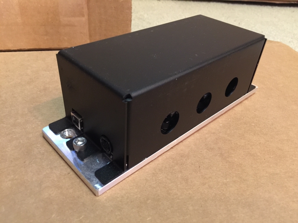
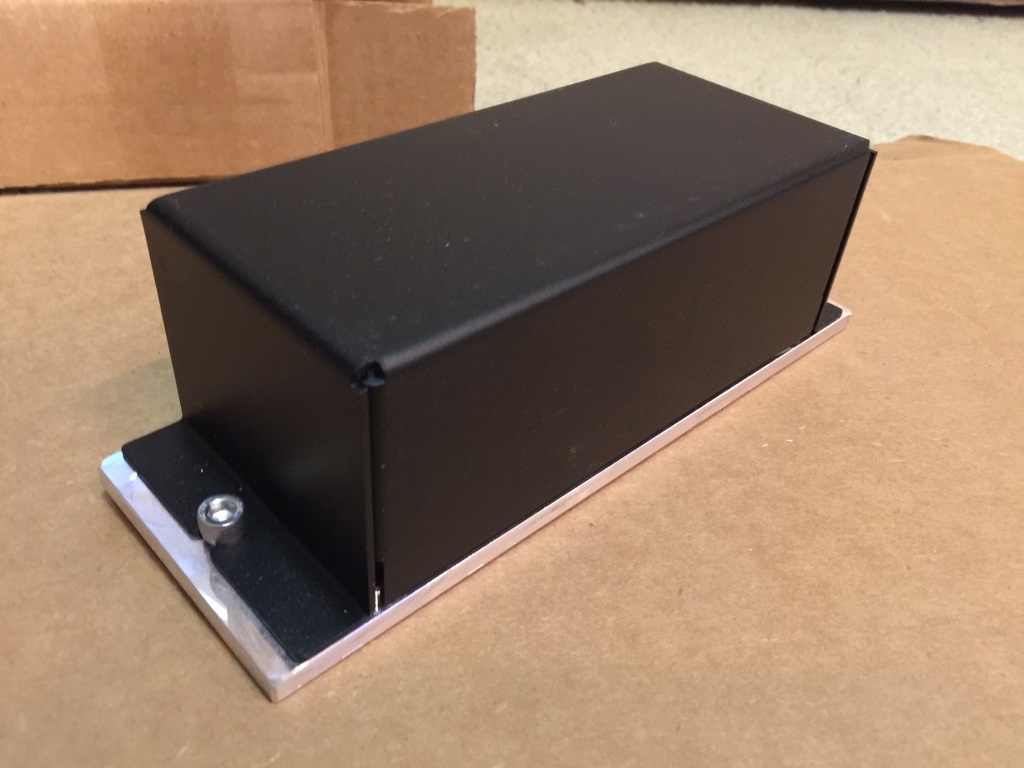
Here is the electronics assembly - the PCB, heatsink, and the new fully-enclosed metal cover. Note the 3 holes available for routing cabling in/out of the enclosure

Here is what you will find upon removing the enclosure. Note the o-rings Carbide includes to protect the cabling from the sharp-edged metal circular cutouts

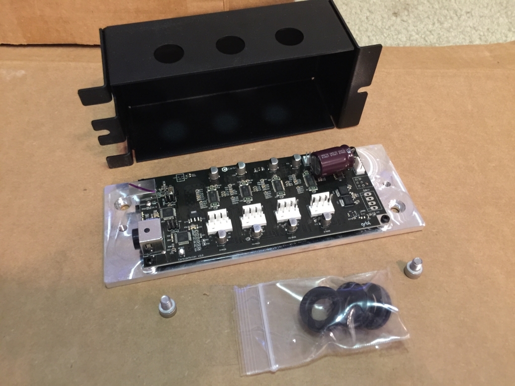
The full kits arrive with the latest 2.3 version of the PCB and the capacitor “fix” - more on questions I have regarding mounting position later

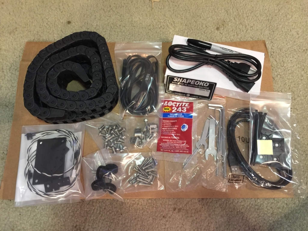
One of the boxes contains all the included tools, fasteners, cable management, serial plate (#1817 in my case), power supply, limit switch kit, belting, and so forth

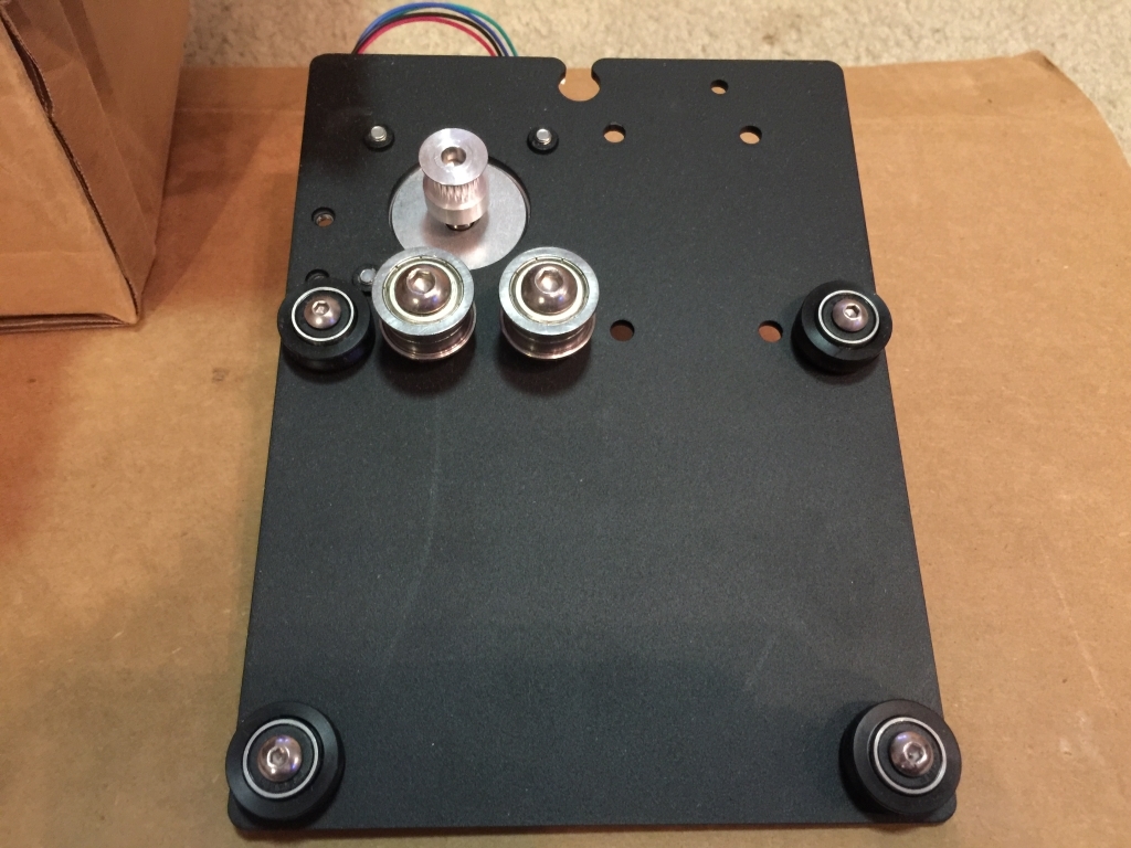
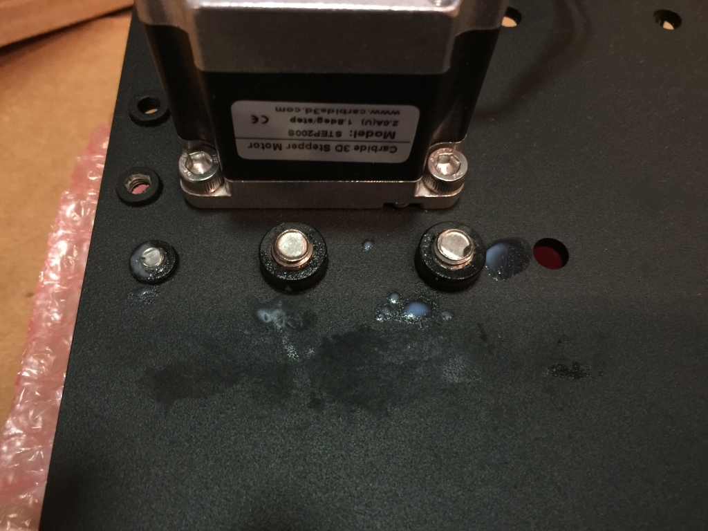
The gantry assemblies are individually boxed and marked left and right - This is the left side assembly as shipped. Note that the stepper motor cable/connector is only about 14" in length which is a problem…

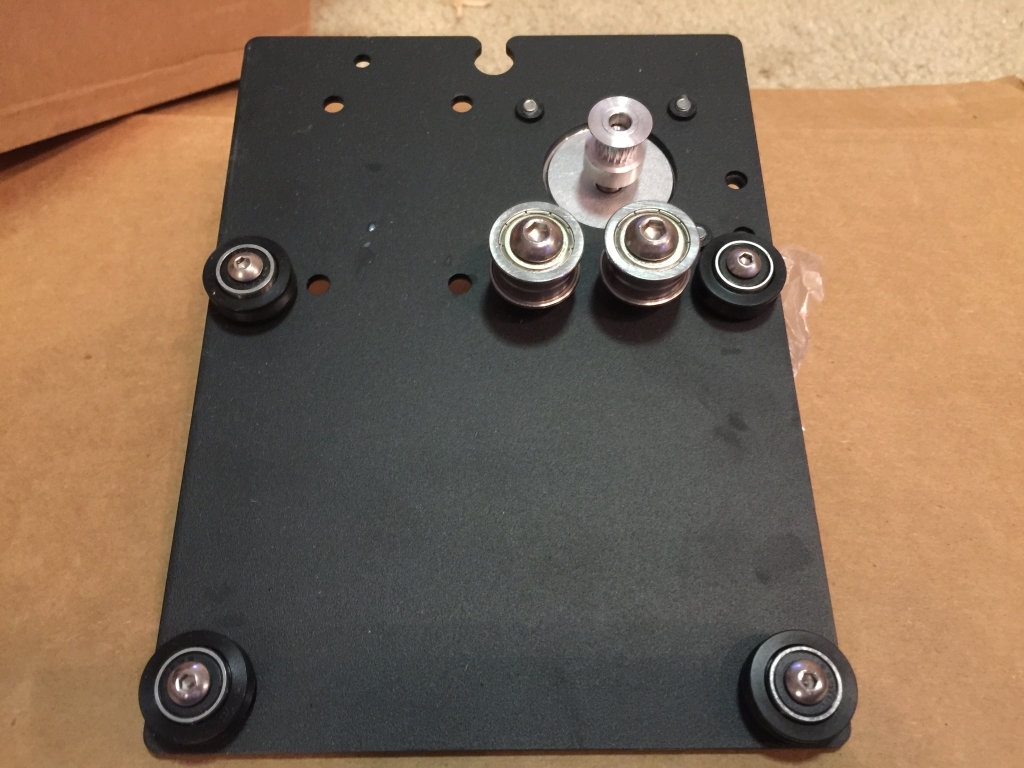
…and this would be the mirrored right-side assembly…Note that the stepper motor cable/connector here is also only about 14" in length which is a problem…

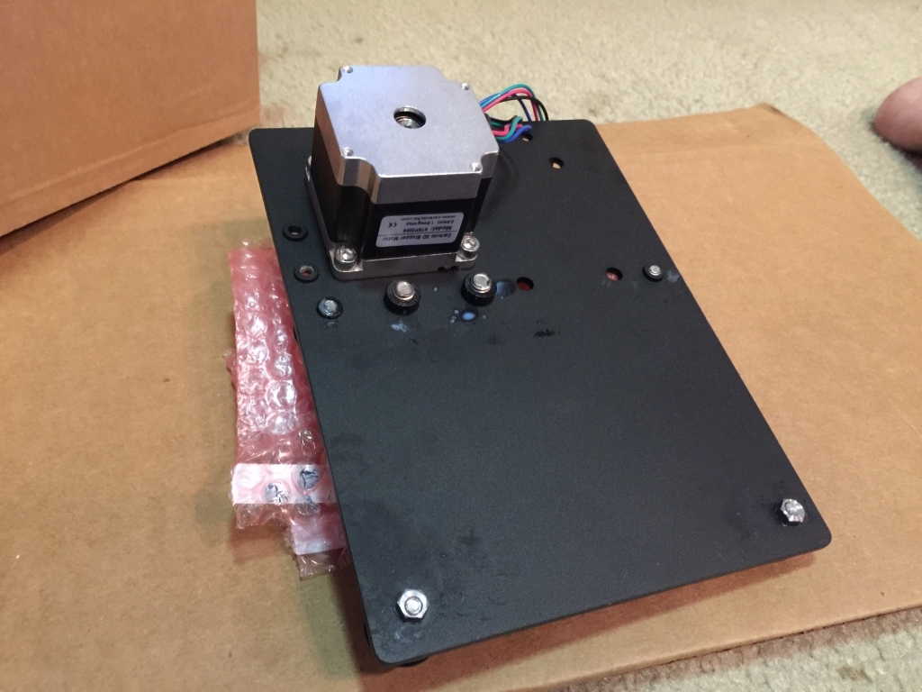
Now for some more items for the support and quality control teams…many of the plates and straps show definite signs of “human handling”…from fingerprints and dirt to grease and “mystery blobs of goo” as shown below.

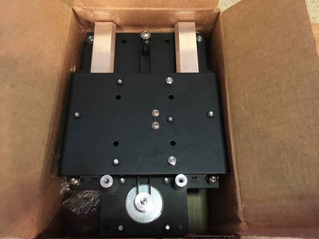
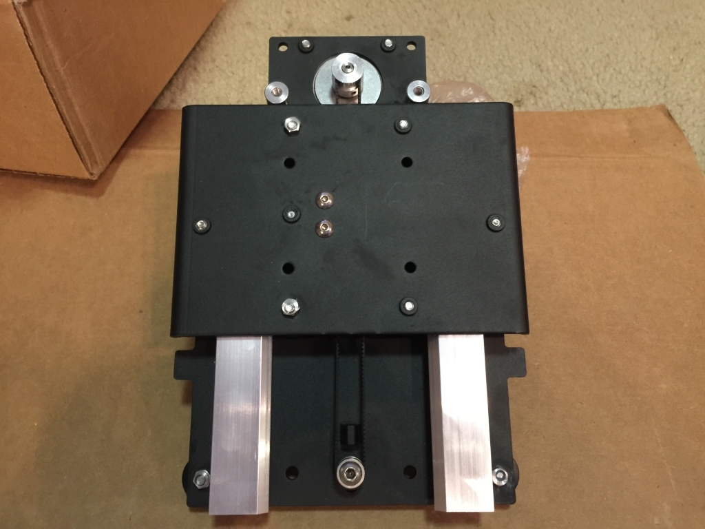
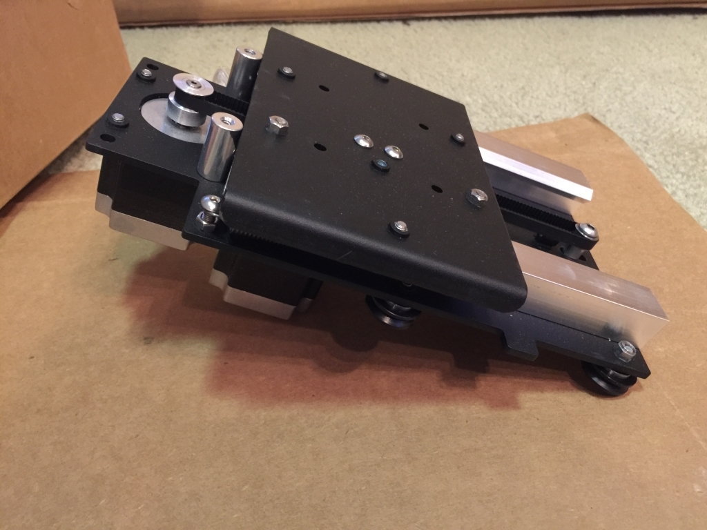
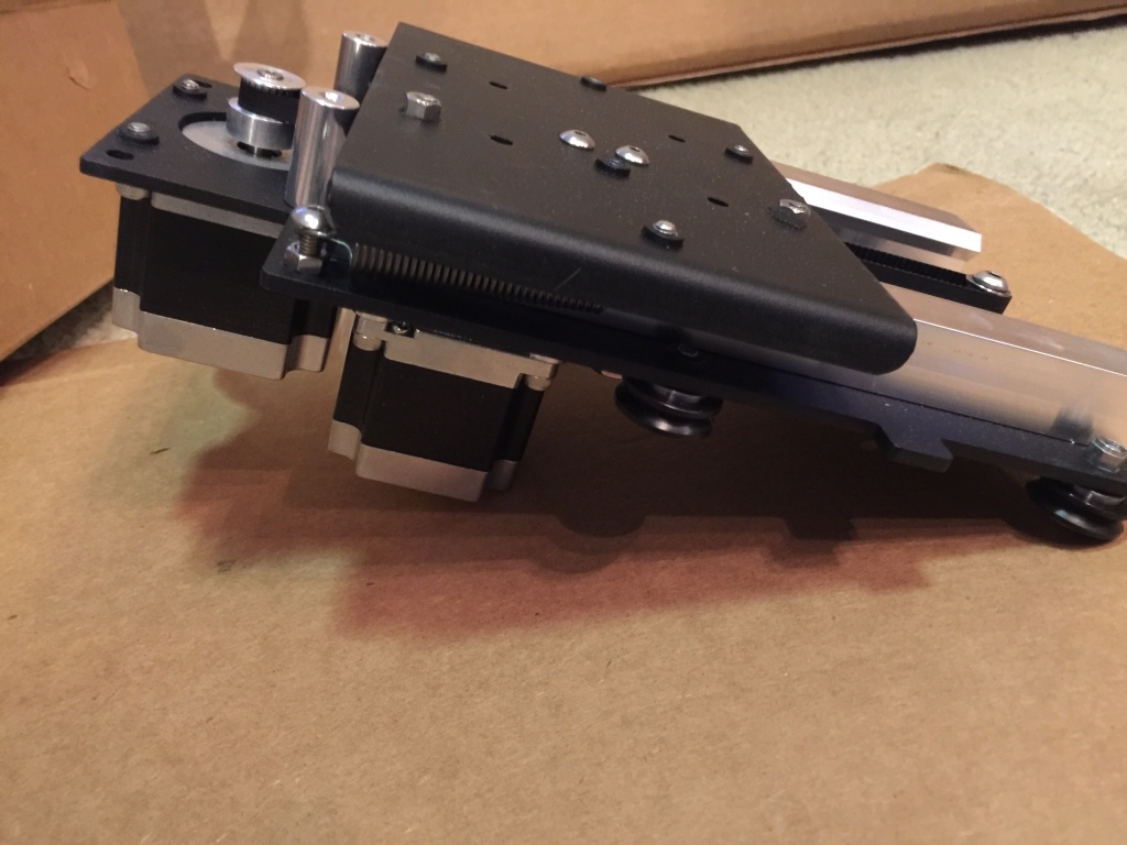
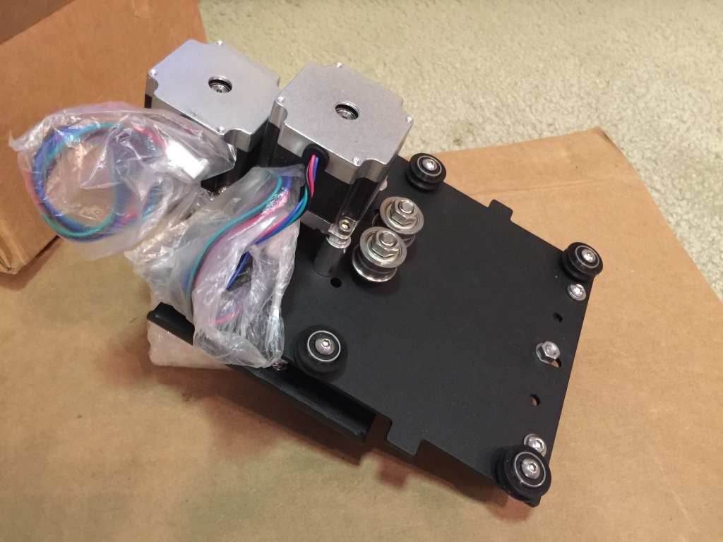
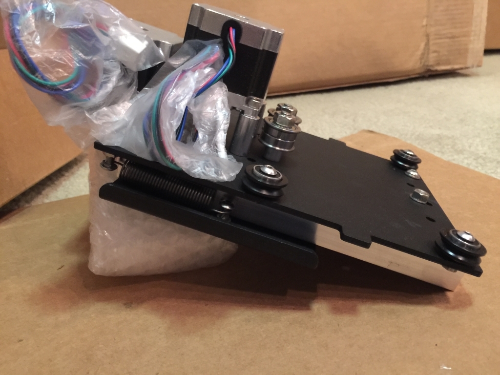
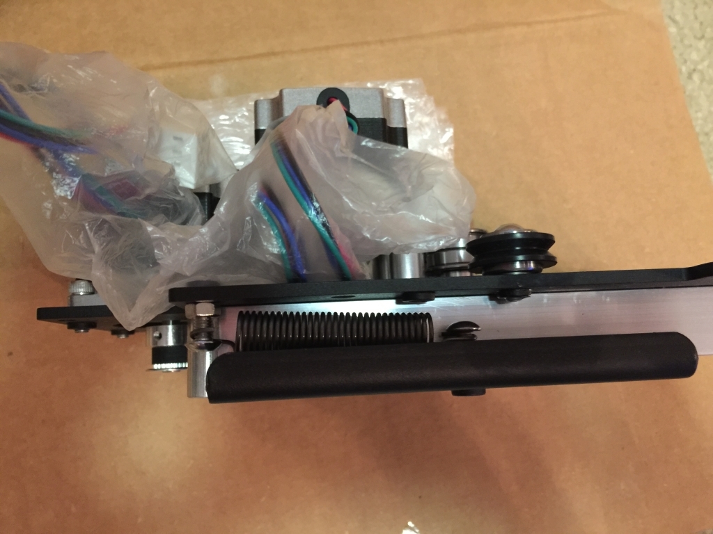
Now for the one most folks are probably curious about…the Z-Axis assembly. I’m providing many shots and angles here to try and answer any questions people might have. Again, this is all pre-assembled and boxed separately. I will mention that it looks like the belting here is only 6mm and not 9mm like the X and Y. Perhaps there wasn’t room for a wider belt and pulleys?

The XXL kit (and maybe the XL?) took a different approach. No more PITA criss-crossing straps that were a nightmare to line up. The following are the 3 beefy cross-straps with folded edges. These run perpendicular to the end straps and parallel to the Y axis extrusions

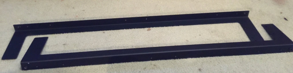
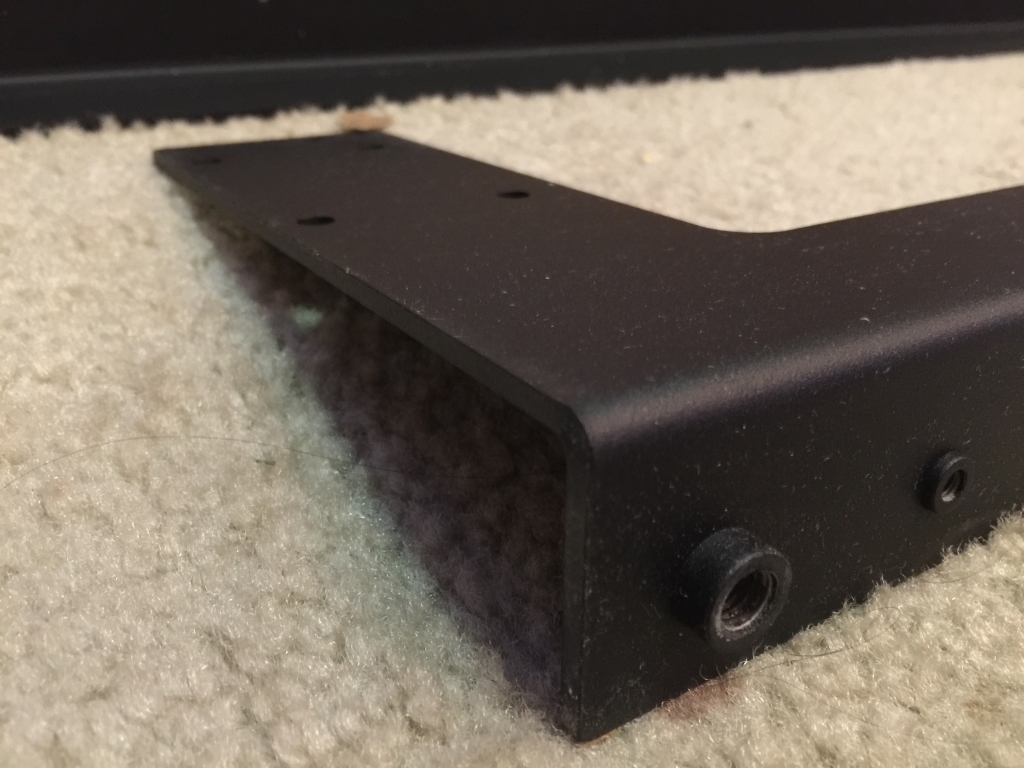
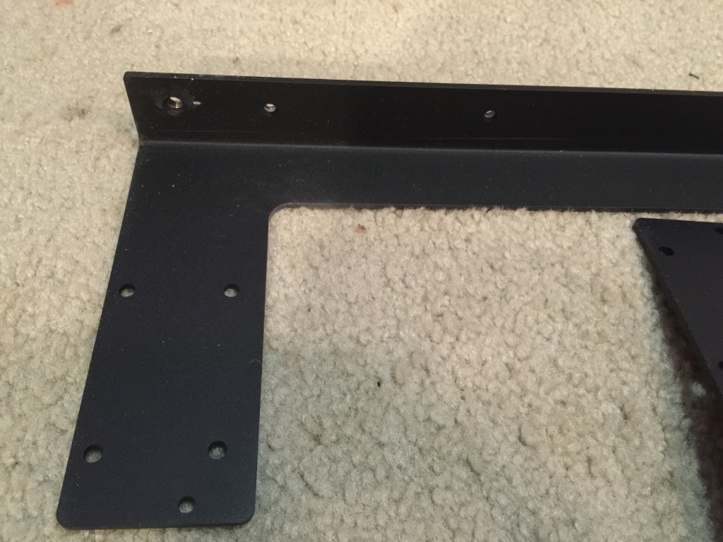
Speaking of end straps, here they are…very hefty and these have the attachment points for the leveling feet.

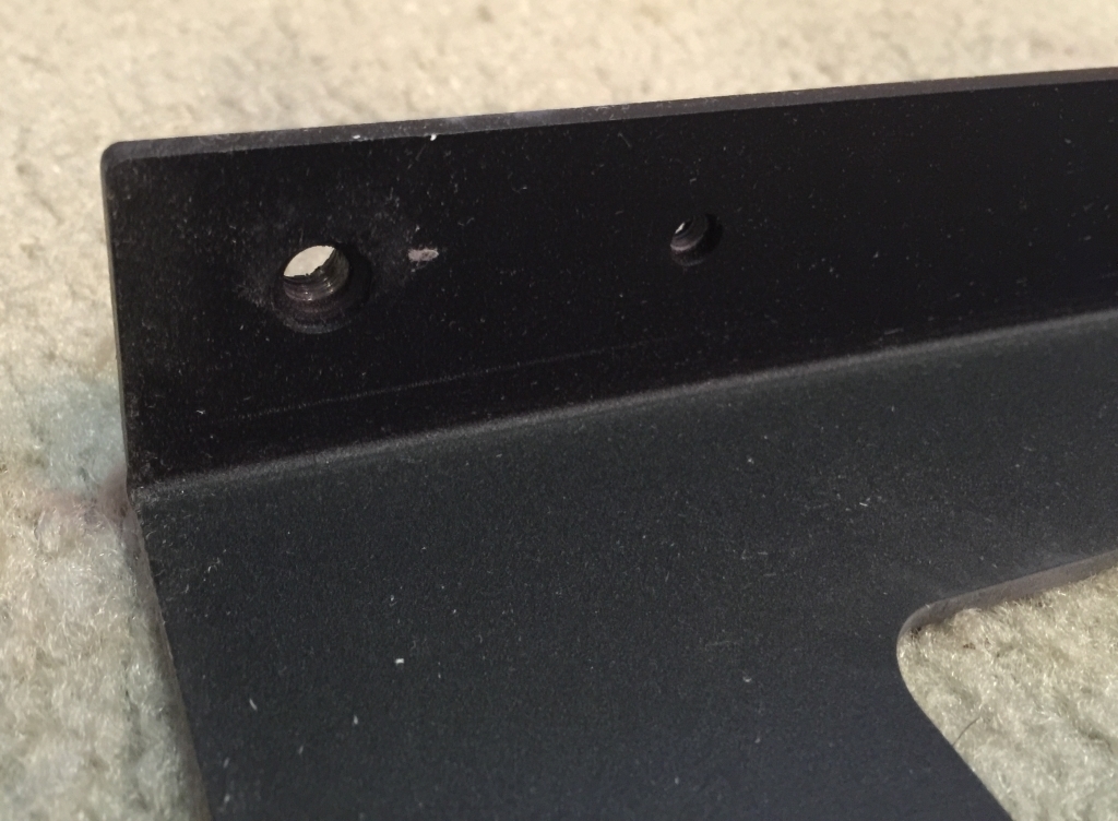
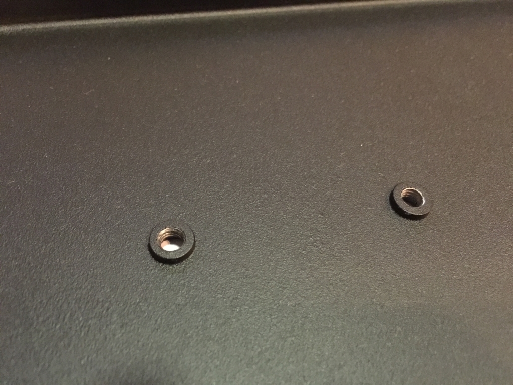
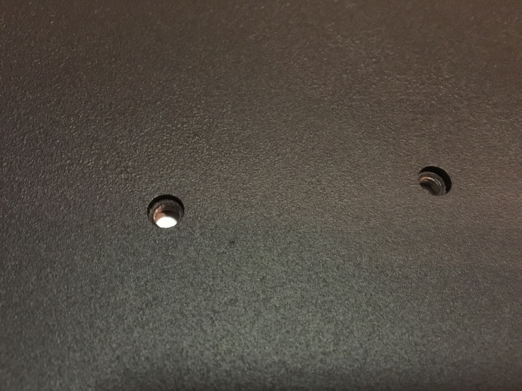
OK, last but not least…the new longer extrusions…one of the packs is marked with an X, so the assumption is that this is meant for the X-Axis. I say “assumption” because this extrusion has two threaded holes in it and I could have sworn I saw prototypes of the XL/XXL with the electronics mounted to the SIDE of the machine on one of the Y rails. Wasn’t this new approach supposed to further resolve the EM interference issues from the Dewalt router? Now, as far as I can tell, the electronics can only be mounted in the same configuration as the original SO3 units. Puzzled…

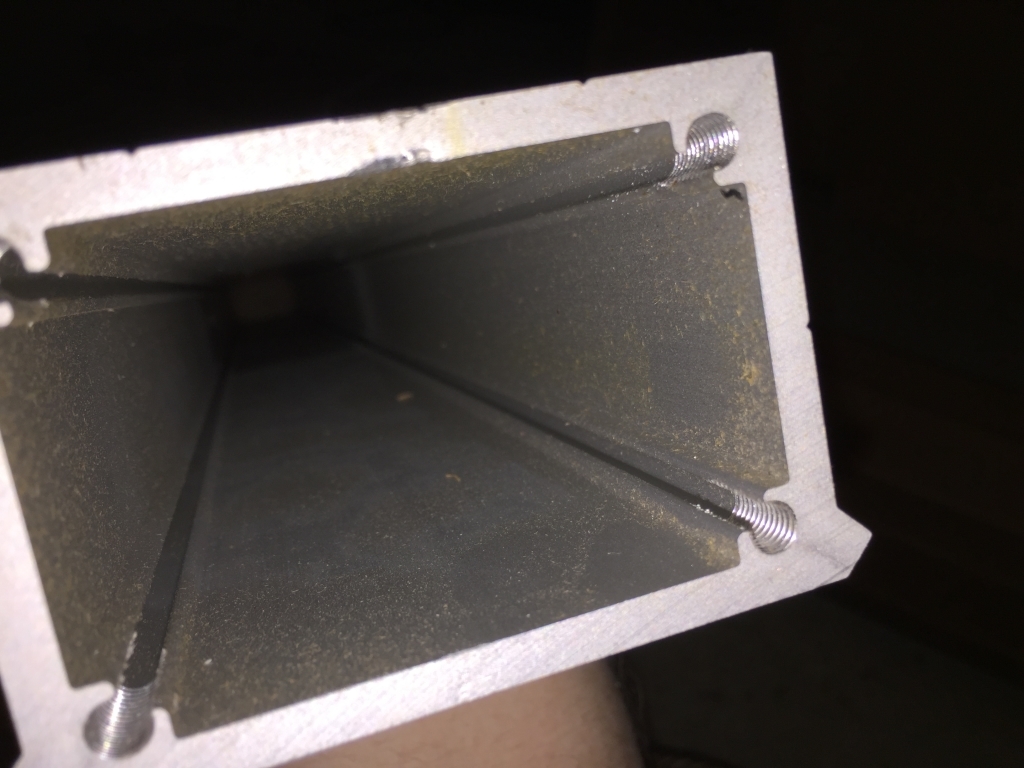
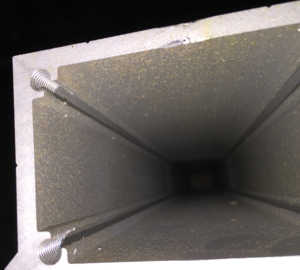
A few shots of the internal extrusion threads - look fine to me…and no leftover aluminum swarf/chips to cut my hands up this time! (Although there IS what appears to be sawdust or something in these?)

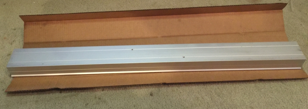
And the dual Y extrusions…lengths seem to match up from a visual back-to-back comparison.

Alright, hope everyone enjoyed the 50ish picture tour of the XXL as-shipped from Carbide 3D/Edward… Happy to answer specific questions anyone may have regarding the contents.

@edwardrford / Carbide 3D support: Here is a summation of the issues I ran across:

  1. Box damage of the INNER container only which seems to have resulted in two banged up wasteboards.
  2. At least one of the pre-assembled V-Wheels is really tight to the point where they almost don’t move without considerable force. The other V-Wheels spin freely as expected.
  3. What’s the “white mystery goo” and other assembly “remnants” all over things?
  4. Is the electronics assembly really still supposed to be riding on the back of the X axis extrusion? I’m pretty sure I saw pictures of it mounted to the side of a pre-production unit…
  5. I still cannot locate any instructions for the final assembly of the kit. While I imagine I could “figure it out,” I’d rather not experiment with various fastener sizes. I can’t even confirm I have all the parts without an official BOM. There wasn’t any paperwork of any kind in the box telling me where to start, thanks for buying, etc. :slight_smile:
  6. The stepper motor leads and connectors are all approximately 14" long. I can see these probably working for the X and Z motors to the PCB, but I can’t fathom how the Y motors can reach the electronics without much longer cables. I went back and looked through the accessories box and can’t find any sort of extensions or other options that would make this work.
  7. Thanks for all your hard work on these new versions…hope this feedback helps!

-craig

4 Likes

Thanks for sharing in such detail!

mark

Craig, Thanks for the write up. A few questions

Are all 3 rails the same length?

How long are the rails?

Are the motor leads longer or do they come with extension cables?

Did the rails and frame arrive without damage?

Are the damaged MDF corners the outboard corners of the wasteboard?

Are all 3 rails the same length?
Yes


How long are the rails?
All are 40"


Are the motor leads longer or do they come with extension cables?
Actually, all are approximately 14" long. I can see these probably working for the X and Z, but I can’t fathom how the Y motors can reach the electronics without much longer cables. I went back and looked through the accessories box and can’t find any sort of extensions. I am going to update my original post with this new issue. I have already submitted a support request and have directed them to this topic so they may address everything. Good call on checking this.


Did the rails and frame arrive without damage?
Despite being a bit dirty, some nicks and scratches, having some grease, and obvious signs of manual assembly, I can’t currently determine if the rails or frame pieces are bent, warped, or otherwise structurally damaged. I’d need to do something more extensive than the basic “eyeballing” that I’ve done so far.


Are the damaged MDF corners the outboard corners of the wasteboard?
Both corners are “inside corners” when the two pieces are mated together with the strapping. Fortunately, they are opposite each other (rather than directly facing each other) along the seam between the two boards. The seam between the two boards would run parallel to the X-Axis and end straps and perpendicular to the Y Axis rails.

Are you sure they’re not 39 and 3/8" or so? That’d make them 1000mm (darn, I was really hoping for 1.2M).

40" == 1016mm which seems odd, but I for one would be glad of the additional working area.

I just double-checked…right at 40" even. The interesting bit is that the waste boards were 42" on their longest side and measured right at 500mm on the shorter edge (I originally provided both numbers in imperial because the first length was right at 42"). So, when mated together correctly, the waste board measures 1000mm/1m in the Y direction. Odd, but maybe this helps understand the extrusion lengths somehow?

1 Like
  1. Box damage of the INNER container only which seems to have resulted in two banged up wasteboards.

Thank you for passing this info along! We’ll see about adding some corner protection before shipping any more!

  1. At least one of the pre-assembled V-Wheels is really tight to the point where they almost don’t move without considerable force. The other V-Wheels spin freely as expected.

Can you check to see if there is a shim (washer) between that hard to move v-wheel and the plate. We’re working through our QC process for these plates and I can see that missing a shim is a potential error that could be made.

  1. What’s the “white mystery goo” and other assembly “remnants” all over things?

We used locktite on all of the hardware when assembling. I see now that we need to do a better job of cleaning up the plates before they’re packed into their shipping boxes!. Also - the ‘dust’ on the inside of your extrusions is probably from the cardboard. I’m guessing there was some leftover oil on the inside of the extrusion (from the tapping process) which acts like a magnet for any sort of dust.

  1. Is the electronics assembly really still supposed to be riding on the back of the X axis extrusion? I’m pretty sure I saw pictures of it mounted to the side of a pre-production unit…

For both machines (XL and XXL) - the electronics should be on one of the outside rails. We marked it as ‘X’ simply because that’s what the people in the shop know as the rail with the controller holes :slight_smile:

  1. I still cannot locate any instructions for the final assembly of the kit. While I imagine I could “figure it out,” I’d rather not experiment with various fastener sizes. I can’t even confirm I have all the parts without an official BOM. There wasn’t any paperwork of any kind in the box telling me where to start, thanks for buying, etc. :slight_smile:

Working on this - I’ll try to get at least an exploded view assembly and a BOM (packing list) out by the end of the day so everyone has something to compare against. Thanks for pointing this out.

  1. The stepper motor leads and connectors are all approximately 14" long. I can see these probably working for the X and Z motors to the PCB, but I can’t fathom how the Y motors can reach the electronics without much longer cables. I went back and looked through the accessories box and can’t find any sort of extensions or other options that would make this work.

You kits should have shipped with 4 extension cables. They would have been in the same box as the Drag chain, tools, and power supply. If you’re missing those - send an email into support (support@carbide3d.com) and we’ll get the missing piece shipped out ASAP!

  1. Thanks for all your hard work on these new versions…hope this feedback helps!

Your feedback has been extremely helpful. We’ve been heads down trying to get ready to ship these machines, and although we’ve spent a LOT of time prepping, we were pretty confident that we’d overlook something.

@WillAdams the rails are indeed 40" exactly (1016mm)

-Edward

1 Like

@Edwardrford Any reason why you are using cardboard instead of foam like the Original SO3. The FedEx guy are very rough for my delivery. My original SO3 box were half way destroyed and tape backup and the internal contain were shifted and damaged. Luckily because of the over protected foam just the controller was damaged and all the plates and rail survived with just a few nicks. Also I am sure they stand the package up so the content inside will shift. My was standing like the leaning tower of Pizza I don’t know how you can protect it better. May be a giant Fragile sign on the box?:grin:

@edwardrford — thanks! glad of the additional travel area.

@eefits — yeah, Fragile stickers don’t help much, usually just an indicator that that one should be pitched further from the pile and stacked on top / last (which for the weight of the SO3 XL and XXL won’t be happening).

Heavy / Team Lift stickers would make sense and using a double wall outer box (if possible, sufficiently larger to allow a layer of expand-os or some similar packaging).

At least you got a machine. I would much rather be using mine, instead of typing on the internet.

@revilo I was talking about my SO3 standard about a year ago. I am still waiting for my Upgrade.

Edit: Sorry misread your post as At least you got your machine. But I am waiting for the upgrade for a project and it requires ~17.5". It was just that close.

A 5ftx5ftx16ft wooden crate marked “Glass” and “Fragile” still gets a forklift through it. The same box with “HIGH CLAIM VALUE” and nothing else seems to be treated with respect.

From my experience in this particular delivery…the XXL box was standing up vertically in the truck. The 4’ 10" FedEx driver lady had a challenging time getting the heavy, awkward box down the 3 steps to the ground and on the hand truck/dolly. Had I not been on-hand to receive the delivery, it would likely have been left in the standing position. Given the packing materials used in my box, the vertical position is the worst possible case to cause and exacerbate damage. More protection, foam, and perhaps a rethink of packing placement might be required to guard against this (obviously) likely scenario.

Since there is no obvious up/down from the non-existent markings on the box, I would also add further protection to the pre-assembled plates. While there were folded bubble-wrap bundles on the BOTTOM of the individual assembly boxes to offset the stepper motors, there was plenty of room in the TOP of those boxes (with no padding at all) for those assemblies to bounce up and down on the V-Wheels and pulleys if the overall shipping box is moved, transported, or dropped in the “upside down” position.

Lastly, I would take advantage of the two empty “spacer”/“filler” boxes by placing one of each end (lengthwise) of the carton in order to provide extra crush protection on both ends. In my shipment, both boxes were placed on one end only.

1 Like

I had the same issues and sent over a note to support. I was missing the extension cables, mounting screws for the router, router mount was a very very tight fit (had to use a block of wood and hammer to get it on, mounting screws for the control box. Having an updated instruction manual would be very very helpful. I was unaware that the box labeled “X” was a side rail and was where the control box was to be mounted. I’ve assembled mine and put it as the cross rail. Is this going to cause a problem? Should I take it apart and put it on a side rail. Really surprised you guys did send out any instructions on this build.

-Tim

Same issues with mine. Did you guys get any hardware to mount the cable tracks?

I don’t believe so, but without the official BOM it is difficult to tell. Also, without seeing a diagram of how they intend these cable chains to be mounted, its not easy to identify the TYPE of part to look for (i.e. is it a simple bolt, bolt and washer, bracket, bracket and bolts, etc???)… I was hoping Edward could identify what parts were missing from my Unboxing shot showing the contents I received in the “accessories” box… heck, if someone from their warehouse could take a picture of the list THEY are using to pack the carton (or sub-cartons preferably) and post it, that would be better than what we have. Obviously, they are still working through some issues on getting THAT list executed 100%, but hopefully the feedback from us earlier adopters will get things squared away…I just hope they prioritize getting these initial shipments corrected such that they can apply that knowledge on sending out much better subsequent kits.

5 photos of an assembled unit would be enough for me. There aren’t very many parts to figure out so a few good photos would be enough for most.

This is true…though as they are seemingly moving this product line towards less of a kit and more of a “light assembly required” option for new-to-CNC hobbyists, they will eventually need the sort of manual that clearly instructs those finishing steps in plain terms. I’m sure, by process of elimination, and knowing how many of certain fasteners are required for certain assemblies, I could just “go for it”… still, I’d like to know what I don’t know…which,in this case, is whether my part inventory is sufficient to build out the machine to completion.

@edwardrford

I’m diving into further detail of the actual inventory I received. In looking at the contents of the “accessories” box, I pulled out the pre-bagged Limit Switch Kit that is included. Unfortunately, it looks like the wires are not long enough to reach from all the switches to the side-mounted (Y-Axis extrusion) electronics configuration. I will add this to my existing support ticket list of issues. I just wanted to note this for others and see if they are running into the same discrepancy?

Outstanding job Craig, no TLDR from where I sit. Suddenly I’m glad that shipments didn’t get all the way through the 2/29 orders. Good lord, isn’t that add on capacitor an ugly kludge - think I’ll have to change that after I get things running and tested.

Thanks much for your efforts.