I’m getting a “Cutter stopped responding” error after I installed my new Huanyang 800W spindle + 1.5kw vfd. Searching around on the forums, it seems like it’s an interference issue with the controller board. However the posts I’ve found are from people who do not have a custom spindle so I’m not sure
I’m able to connect to the cutter, initialize the machine, and run GRBL commands such as M3 S(RPM) to spin the spindle, however after around 15-20 seconds of the spindle running, carbide create would be “busy” and will give me a “Cutter stopped responding” error.
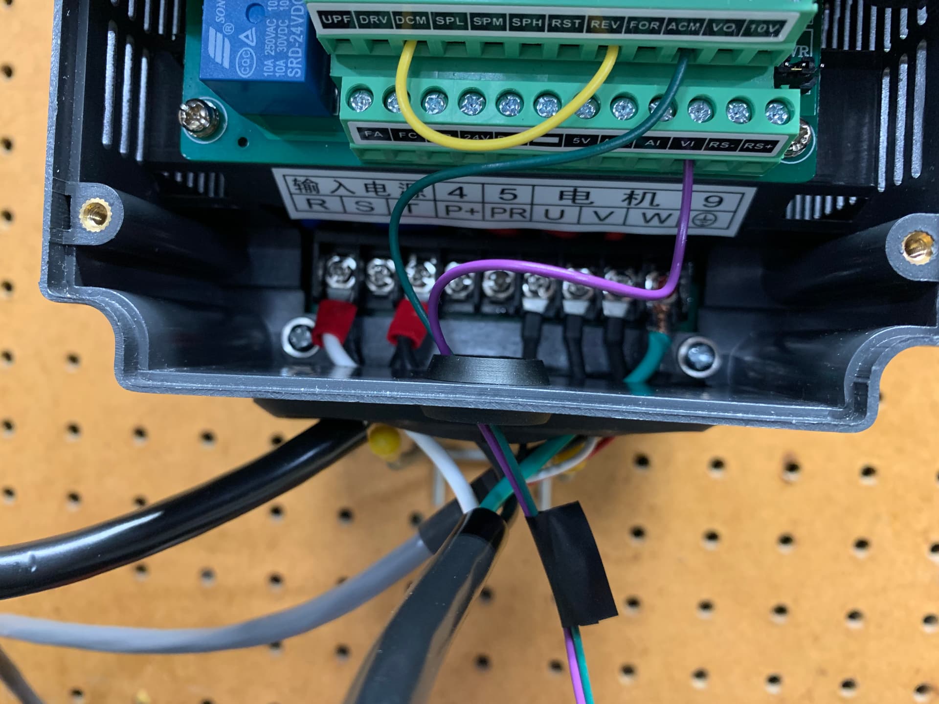
On the VFD, I have the following pins connected:
DCM → REV (hardwires the spindle direction)
ACM → SO4 GND from the bitrunner molex
VI → SO4 PWM signal from the bitrunner molex
R → 110VAC outlet wire
T → 110VAC outlet wire
U → Spindle U phase wire
V → Spindle V phase wire
W → Spindle W phase wire
GND → the input power ground wire
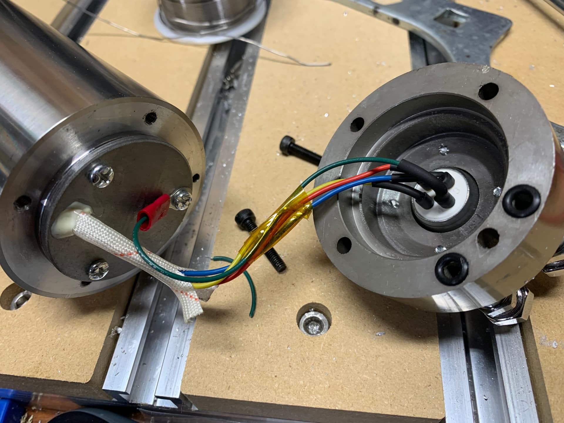
GND → the spindle ground (I opened up the spindle and ran a grounded the chassis to pin 4 and confirmed continuity afterwards)
GND → The shielding wire from the shielded 18/4 wire I used
grounding the Shapeoko: there is great video from @LiamN in this thread. You’ll want to actually check continuity between your spindle body and the shapeoko’s ground.
running the spindle power cable away from the other Shapeoko cables. But I suppose you already did that and used the drag chain where the router power cable normally does.
And then there is the hit and miss approach to use different outlets for the Shapeoko and VFD
Checking the grounds are star grounded, that only one end of the cable screen is grounded and that there’s a power filter between the VFD and the incoming power are all things I’d do here.
You’re correct on using the router drag chain for the spindle power wires. I have it routed in the router drag chain along with the coolant lines.
So pretty much I just have to make sure the Spindle has continuity with the Z carriage, and run a ground from the Y carriage back to the VFD common ground terminal? I watched the video that @LiamN made and I think I get the big picture
Problem solved I just broke in the spindle without any more issues.
I sandblasted the inside of the spindle clamp to get rid of the anodization, that way it could make direct contact with the spindle ground. Then ran a wire from the spindle clamp to the back side of the Z carriage.
Then I ran a ground wire from both the X and Y gantry and connected it to the ground point inside the VFD. This seems to have fixed the interference issue.
Remember to start it up at lower speed and let the bearings / grease warm up first use of the day. Some folks have done auto warmup scripts, my VFD is not connected so I let it run at ~ 3.5kRPM for a few mins whilst I initialise the machine and set up the workpiece. The viscosity of the grease changes a lot with internal temperature in the bearings and running it full speed from cold is a good way to pump all the grease out of the bearings, which is not good.